Through the past months following two cool gears ideas landed in our mailbox. Enjoy!

The sky is our ocean
Through the past months following two cool gears ideas landed in our mailbox. Enjoy!

As softly indicated in our Rendering post, our current focus is on designing a gimbal arms. These will serve to extend gimbals configuration away from gondola and align them with main thrusters.

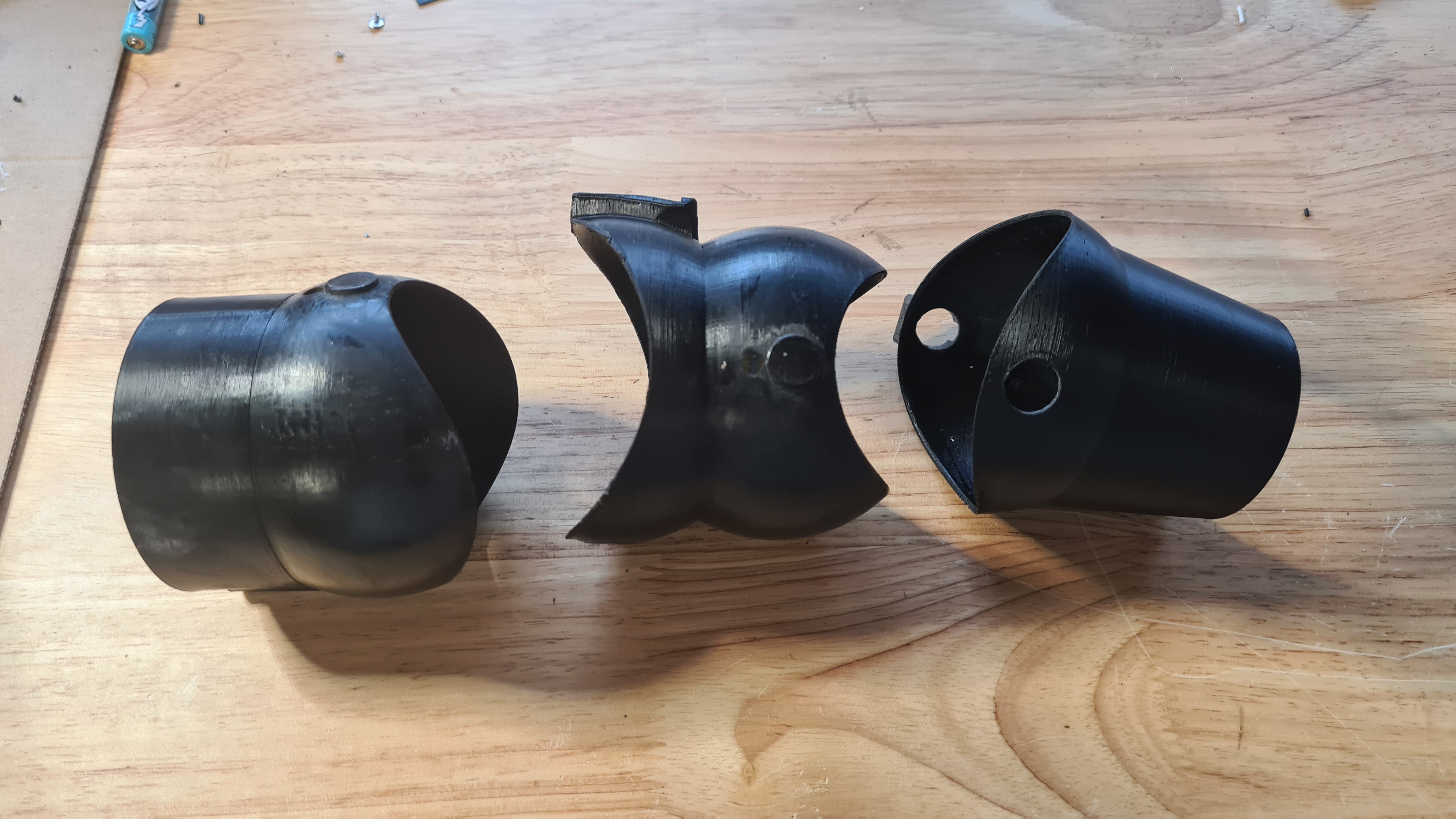
To be able to print such a monster (60+ cm end to end) it got separated in three sections.
1/ The gondola clamp
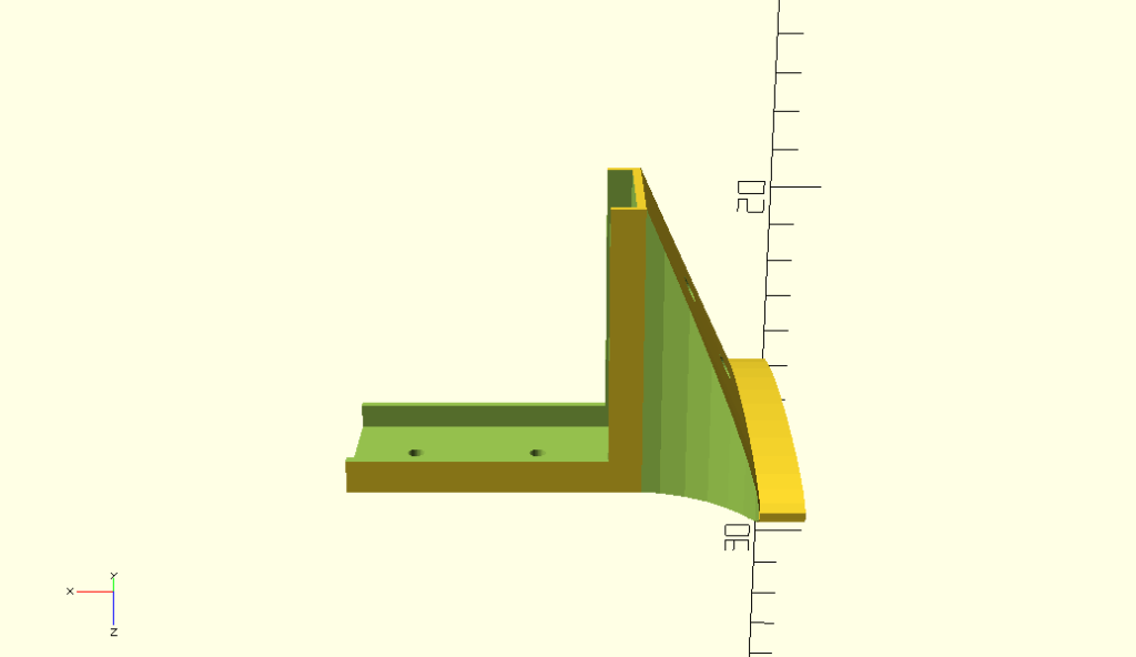
I think that pictures will tell more than explaining here what and how.


Overall this clamp is pretty stable and does the job, however joint with that mid-section is too klanky and needs re-designing.
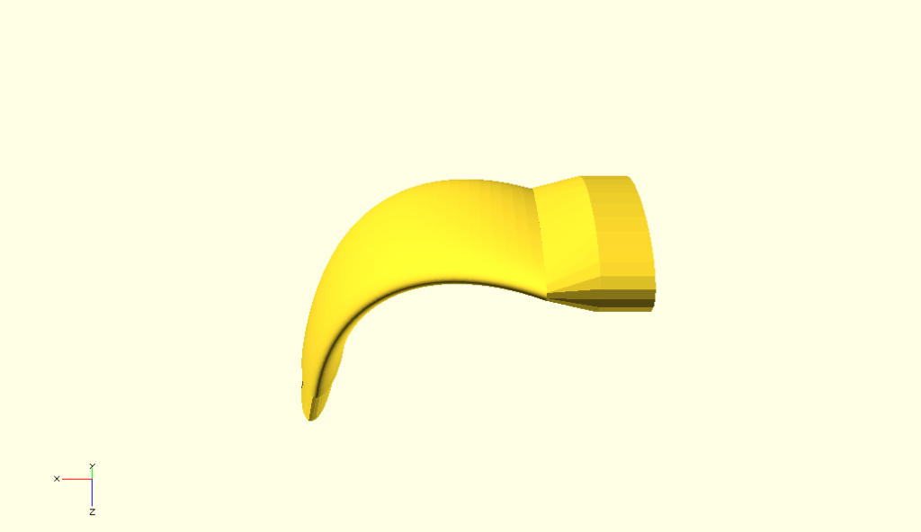
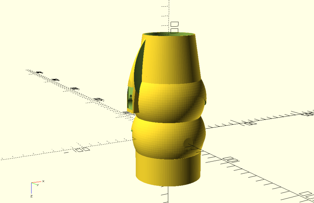
2/ Mid arm section

How simple it looks, it took several hours to design a shape which starts with ellipse cross-section of one size (6cm) and skews sideways into another ellipse of a different size (4cm). I am not going to spam here with a code for the others, but I am actually pretty proud of this part so here it comes!
fn=32;

#parameterised 2D ellipse
function ellipse(r1, r2) = [for (phi = [1 : 1 : 360]) [r1 * cos(phi), r2 * sin(phi)]];

module tube(r1, r2, rr, R, th) {
  D() {
    skin([for(i=[0:fn])
    transform(rotation([0,80/fn*i,0])*translation([-R,0,0]),
      ellipse((r1+(r1-r2)/fn*i)/rr, r1+(r1-r2)/fn*i))]);


    assign(r1 = r1-th,r2 = r2-th)
    scale([1,1.2,1])
    skin([for(i=[0:fn])
    transform(rotation([0,80/fn*i,0])*translation([-R,0,0]),
      ellipse((r1+(r1-r2)/fn*i)/rr, r1+(r1-r2)/fn*i))]);
  }
}

module mid_section() {
  D() {
    Ry(10) {
     skew([0, 0, 45, 0, 0, 0])
     tube(r1 = 3, r2 = 1.5, rr = 6, R = 25, th = 1);
    }
  }
}

mid_section();
Design above allows printing all that monstrosity quite efficiently “laying flat”

It clearly was our longest print so far – it took 18hrs – and seeing how that worked out it already needs redesign. An internal reinforcing rib is needed and joints on both sides needs some sort of clamps to be more solid.
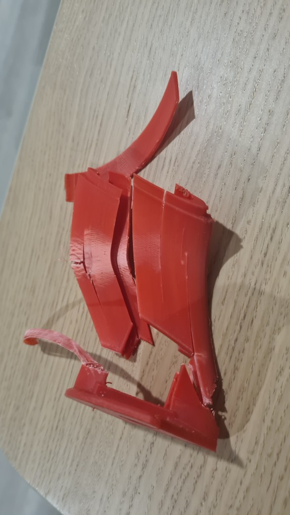
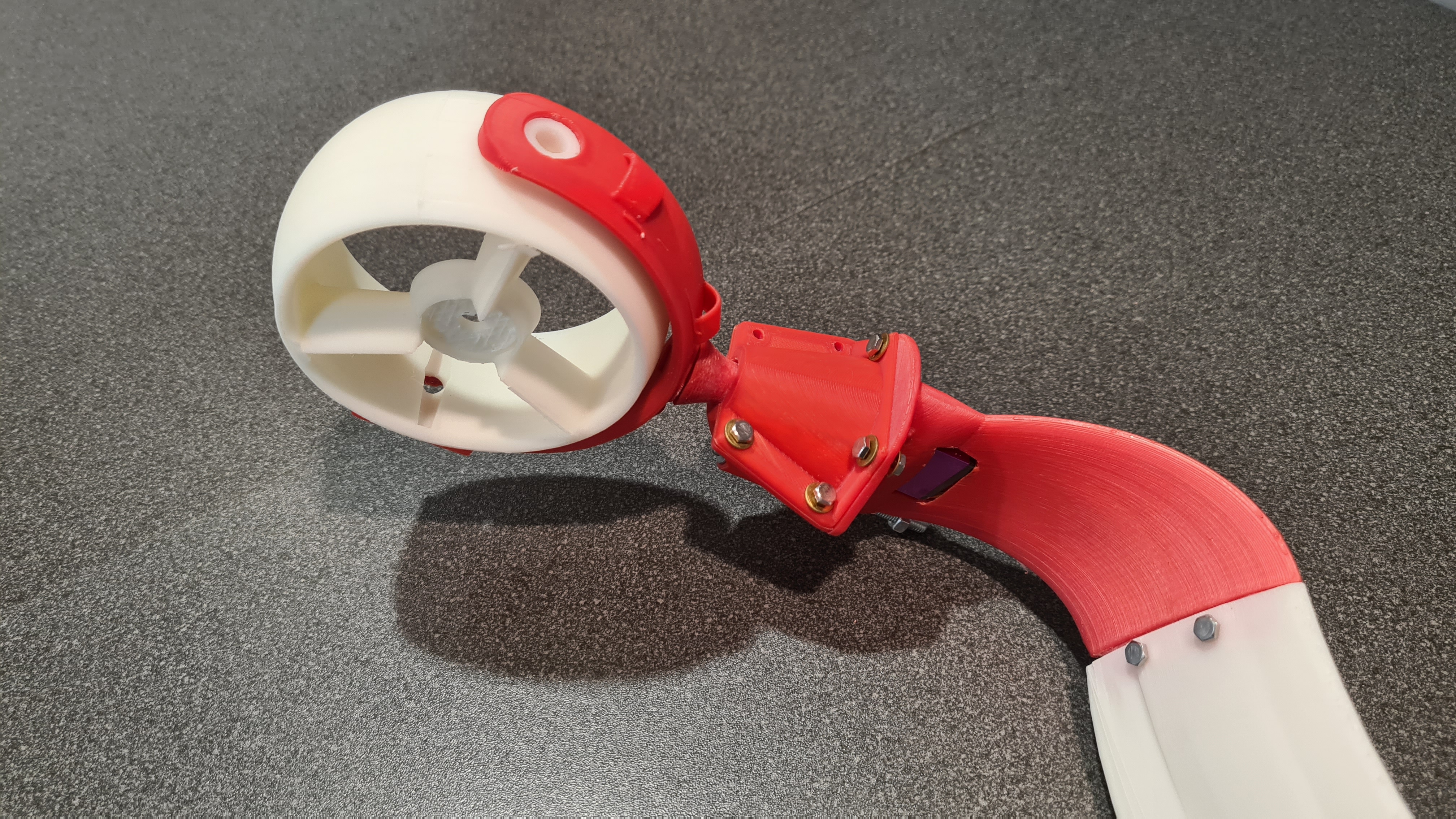
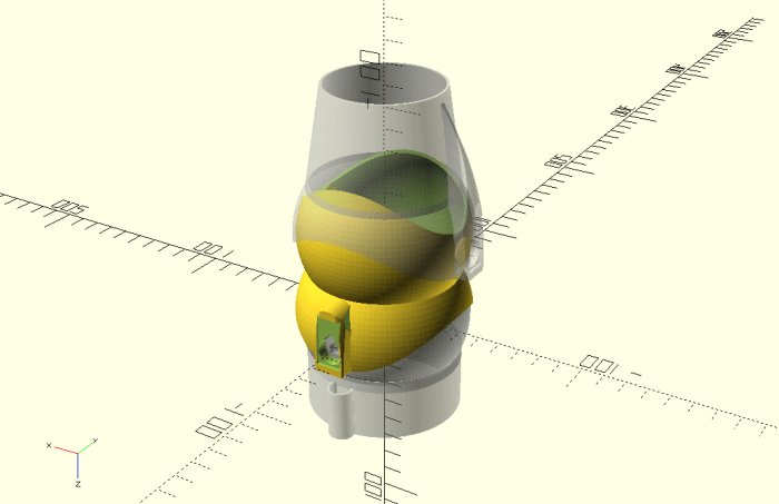
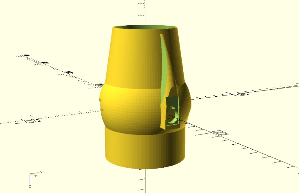
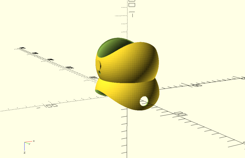
3/ Gimbal adapter section
When having that above mid-section in hands, designing this part was much easier. Practically the same, but smaller + bit of fun when scaling cylinders to make them fit that ellipsoid cross-section. Problematic part came when attempting to join it with the gimbal as there was not enough material to make me confident about it withstand some reasonable sheer forces (400N). Simple “test by Ondrej” demonstrated that I was right.
Video from printing here:
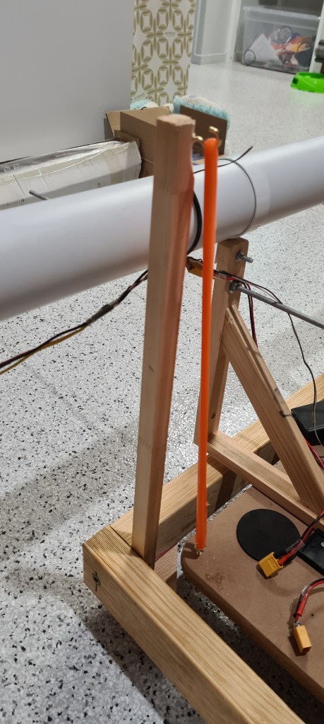
Anyway, at the end it all clicked together (with bit of sanding, heating and persuasion) to the point where we could demonstrate its first prototype!
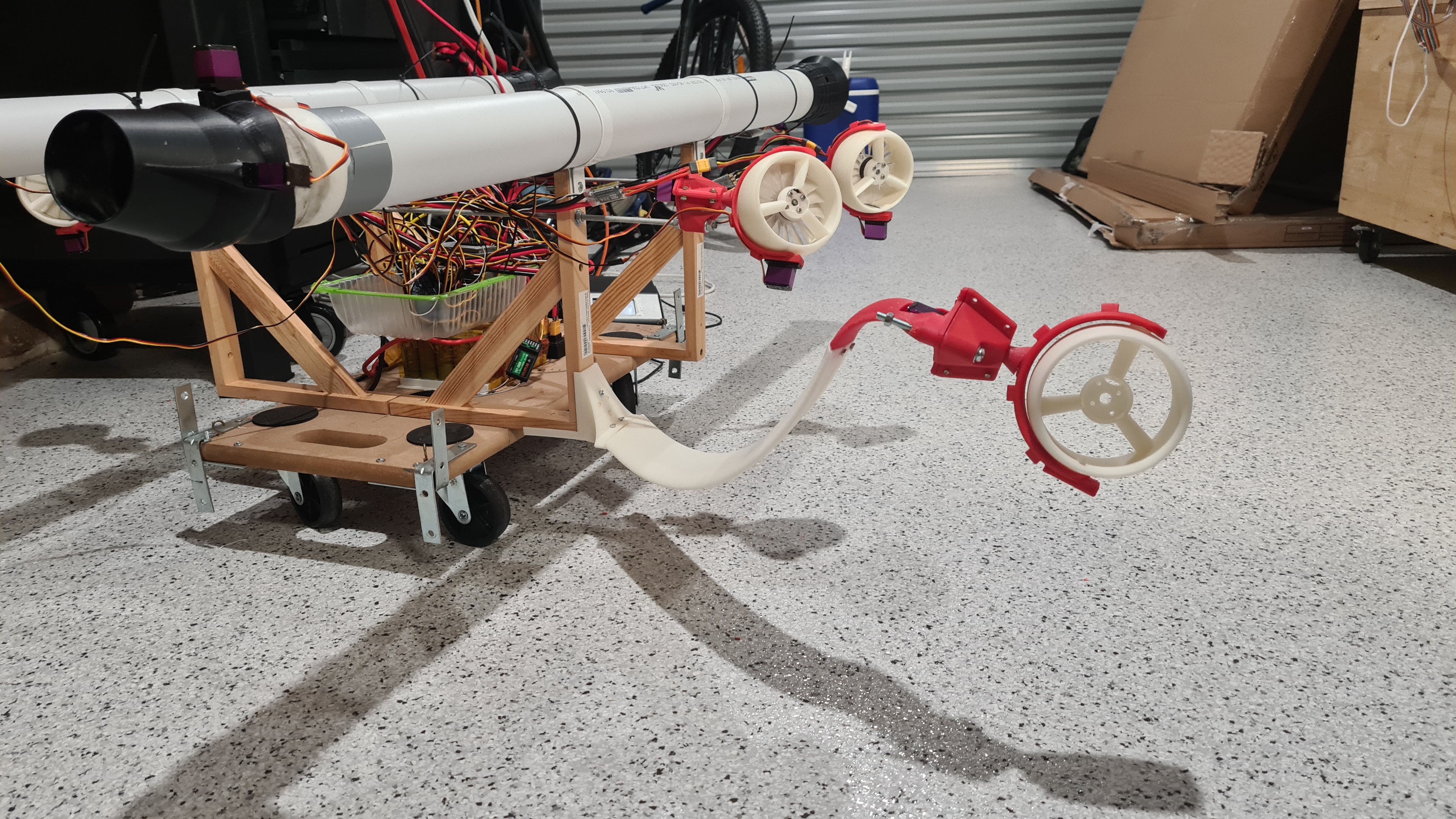
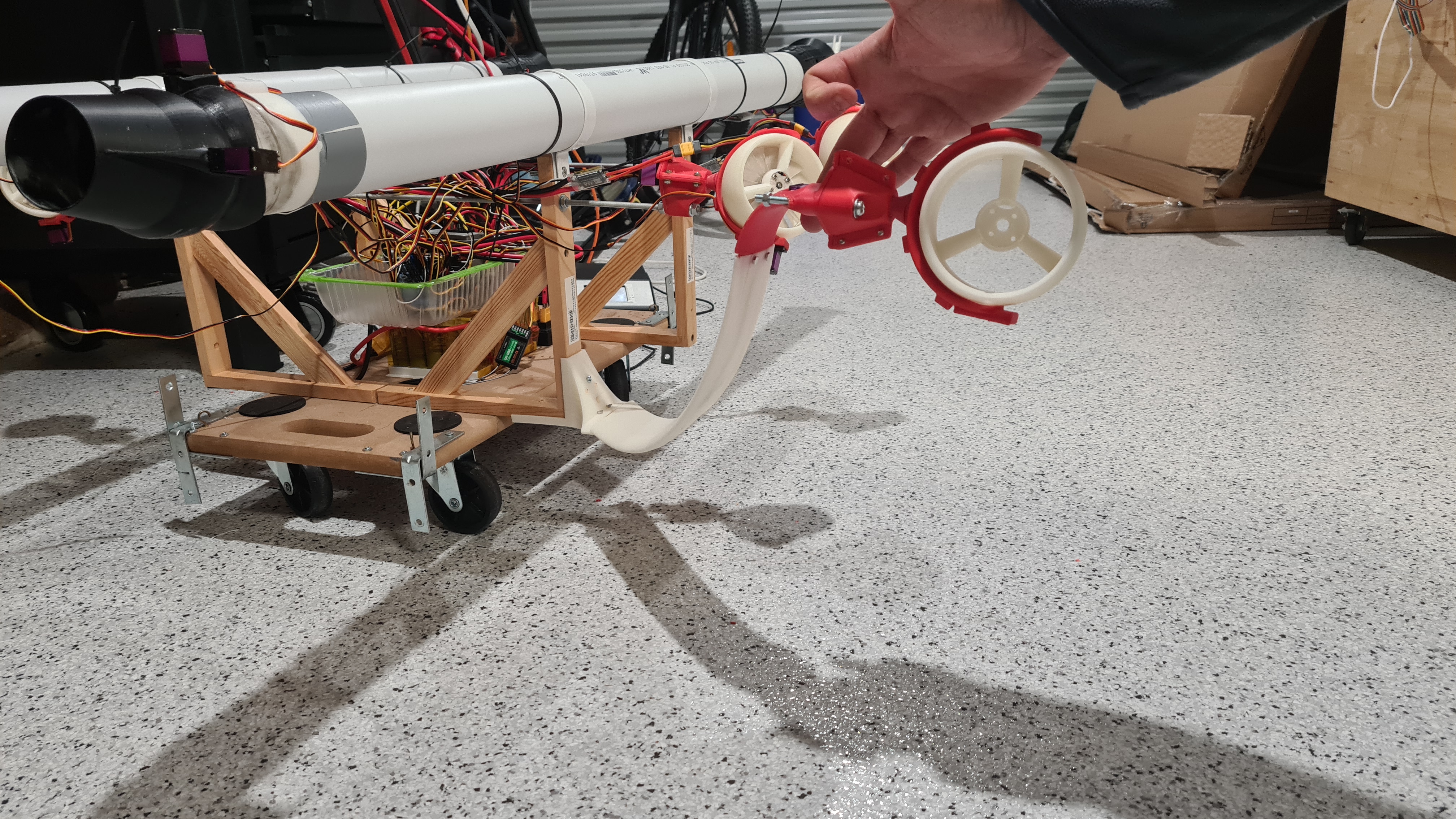
As you can see above, there is quite a sag on that arm which is caused by multiple design weaknesses, but mainly the joint between the main clamp and the long arm. That needs to be surely reinforced. I am still liking it as it really looks pretty close to that original rendering, just this is real! 😀


As always, let us know your ideas or any comments whatsoever, all welcome!

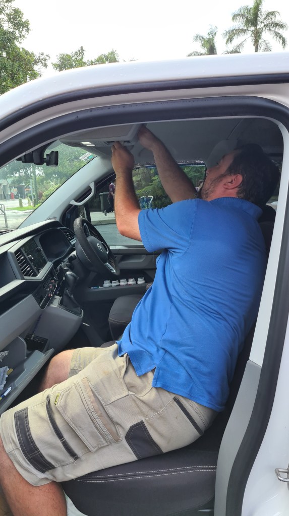
Vilda, knowing that we are having too much fun with our 3D printer, asked us for a favour and improve one of his car’s slots with power sockets. Well me, knowing that Sebi is having too much fun with our 3D printer, asked him to do that job for Vilda! 🙂


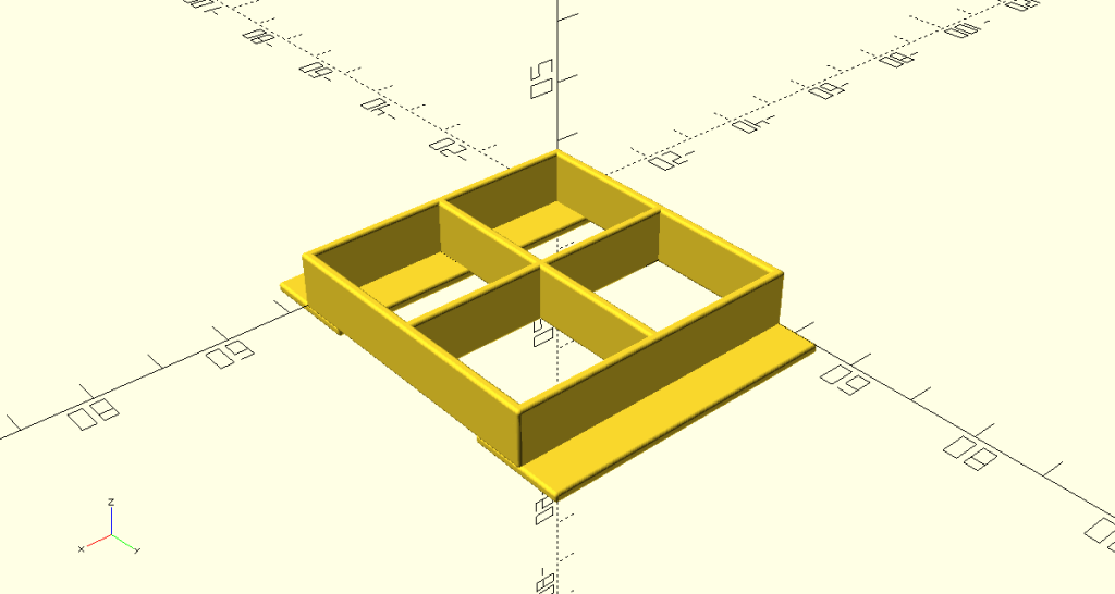
Anyway, Sebi spent few day on in and it worked out so well that I decided to document it in one of our posts. Here comes screens from OpenSCAD.
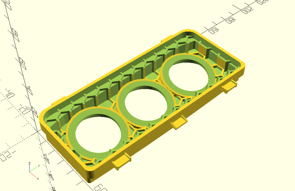

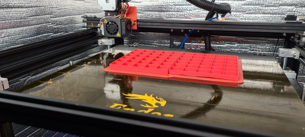
This is how it worked out in a slicer (CURA).

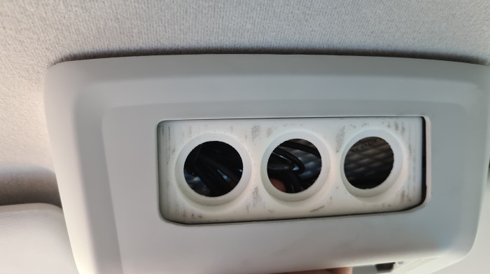
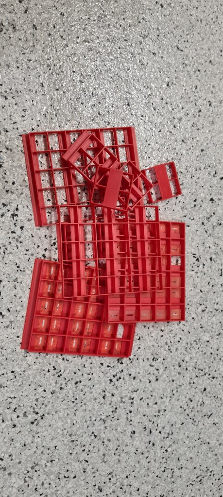
As always it took “just” few hours to print it and we’ve ended up with a final product!


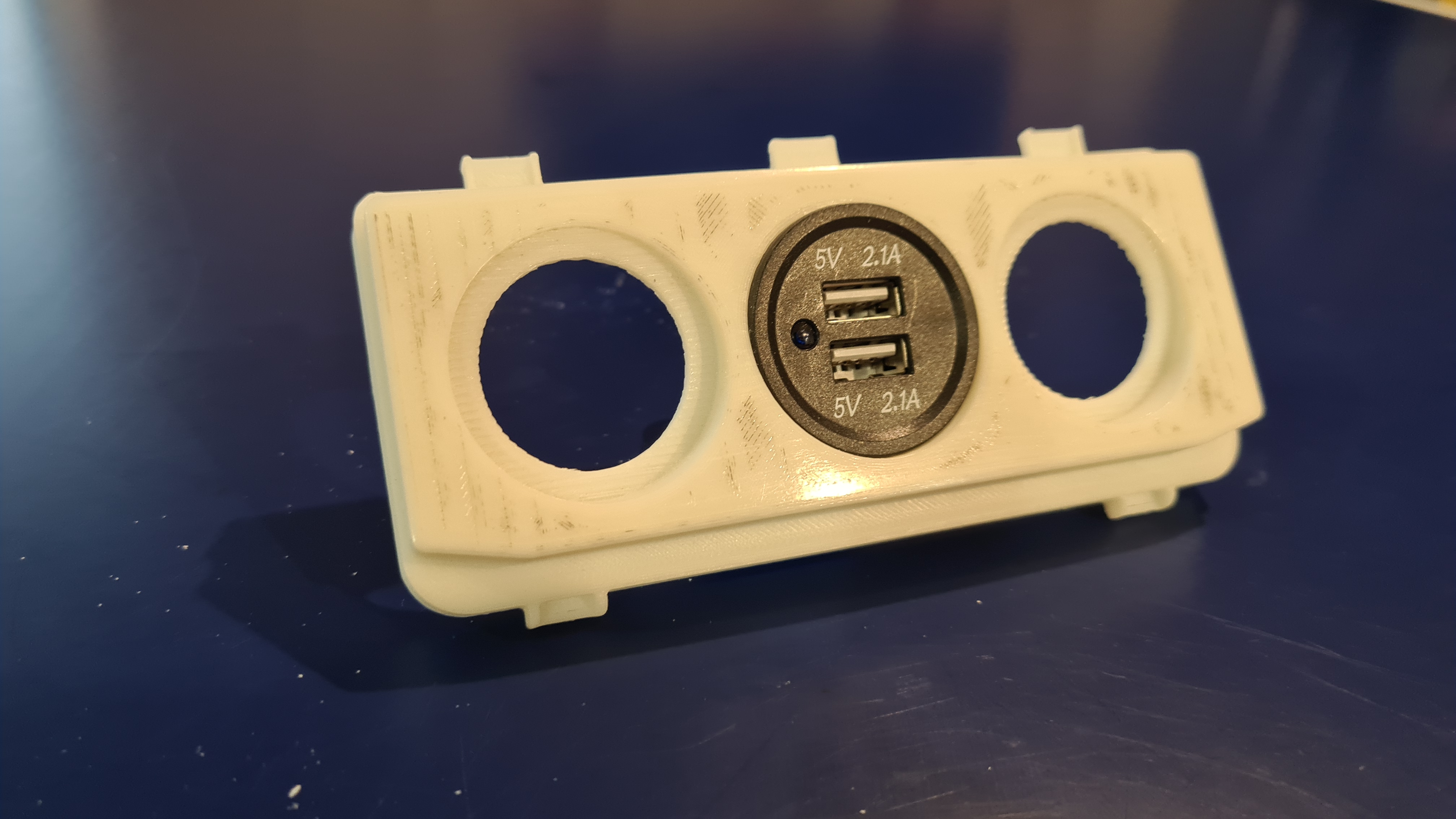
Vilda mounting it in his car.
Unfortunately edges haven’t had the same radius, but nothing Vilda can’t fix with bit of sanding 😉
Well done Sebi, this looks like a pretty good job done!
UPDATE 3rd Jul 2022 – Vilda provided several pictures from a final assembly – Thank you Vilda 🙂


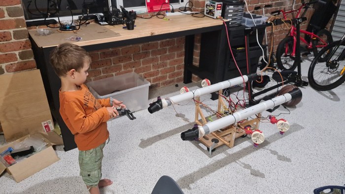
It took a while, but we have those new Vectoring Thrusters working! I’ve asked our new airship engineer Filip (4yro) to give it a go and he did an excellent job demonstrating its operational – with confidence. 🙂
Thank you Filip! 🙂
And now Sebi, with engines … enjoy the rumble!
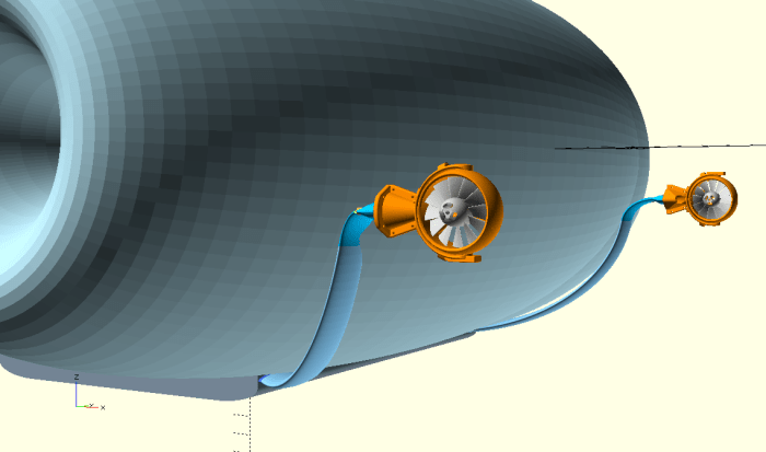
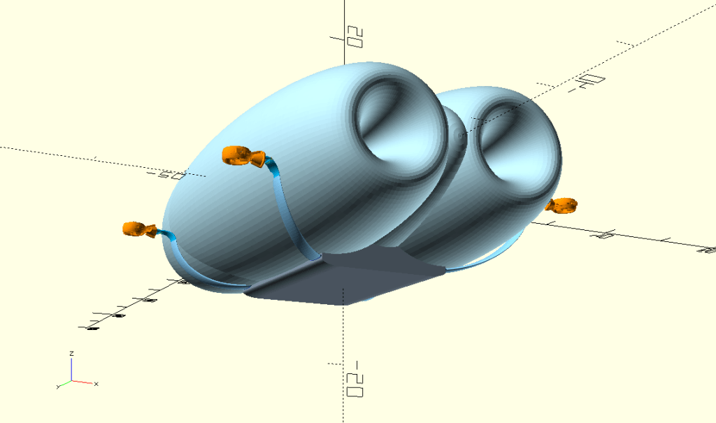
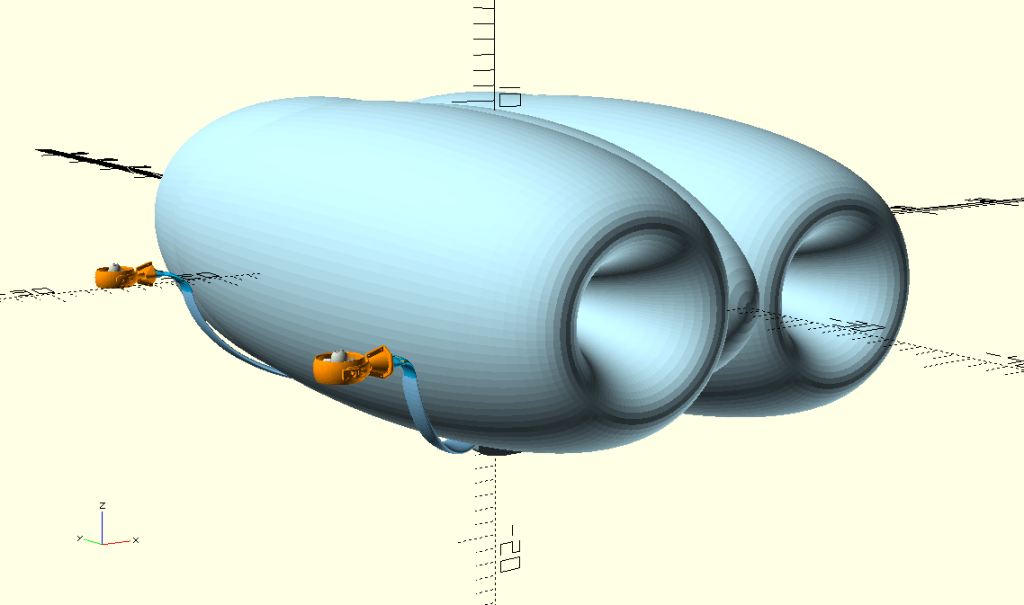
I did few updates to our main design in a model model preparation for some experiments with OpenVSP. Seeing how that worked out nicely, I took several pictures and prepared them in a small gallery, including tiny comments.

Front view, all three envelope segments are nicely aligned, showing two main intakes. Gimbals are bow-facing on sides, attached to a gondola with wide bent arms copying a shape of the envelope.

Side view – two gimbals hanging on long arms demonstrating those being skewed to get a cruciform (quadcopter drone, but in style).

Rear view, vector thrusters are not present, but those will be located in a centre of both side envelopes. (Central envelope has no duct, it serves as a ballonet.)

Isometric (from below) view – I just like how it comes together on this picture, but it also serves as a reference for the following one.
Same picture as above, but notice gimbals are now up-facing.
Same trick as above, just a different viewpoint.

I took one more showing forward-facing gimbals in this angle.

Well, this is something different – envelope is missing here to provide better overview of gimbals orientation. Gondola is just a placeholder here, but demonstrates that it’s main part is hidden in the airship body to lower its air resistance.

Now this is our holy grail, our airship transformed in a drone (gimbals are facing up)!

The final one – close take on gimbals. I think they look pretty impressive mounted like this!
Well, as always let us know what you think! All (constructive) comments welcome. 🙂
I’ve been discussing how to build a heater for our Carbon Fibre curing with Serge and he proposed to simplify things greatly. Instead of an aluminium tube with a copper wire winding type – he came with a simple cooking heater wire which would be placed in a centre of our tube.

As usual with Serge, he instantly grabbed a spare one and gave it a try! 🙂
It is awesome & thank you Serge! This really solves more than a few things – even wire winding, fitting tube in a tube, mechanical protection of a wire, temperature control and also simplifies our design quite dramatically!
Still, I made couple notes which we need to think through:
Once again, Thank you Serge!!!

PIC microcontrollers are a family of specialized microcontroller chips produced by Microchip Technology in Chandler, Arizona. The acronym PIC stands for “peripheral interface controller,” although that term is rarely used nowadays.
The reason I got into PICs was to experience a low-level world of make it from absolute scratch. If any of the following apply to you, then you should definitely give it a go:
When starting with PICs its a good idea to get one, you can get these from microchip.com or I got my first one and a few others from a local tech store. Alongside a PIC you should also get a programmer, the one I got is the PICkit3.5 which is a slightly improved clone over the original PICkit3, I got it from here: long-link. And with that finally I would recommend a few dupont wires and a power source of 5 volts.
I started with the PIC16F630, however I recommend using the PIC16F690, because it makes it easier to follow the guide I followed: https://picguides.com/beginner/introduction.php
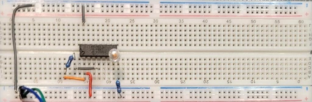
Once you have received all the items and put it all together as per the guide I have a few debugs to address:
At the end after I have resolved this page of the guide: https://picguides.com/beginner/digital.php, I have ended up with the resulting project:


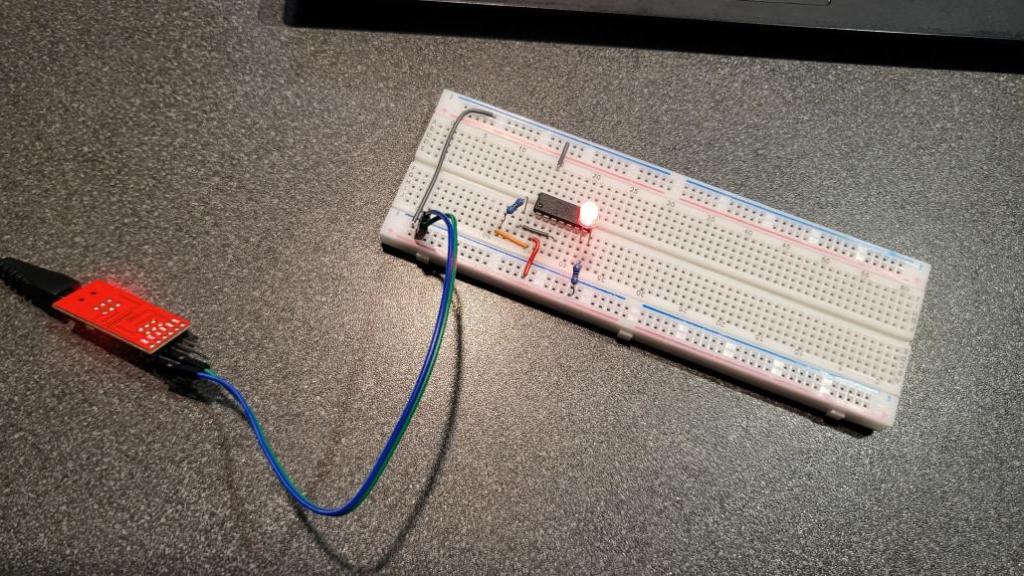
And that concludes my starting with PICs, Next I hope to create a servo-setter for my dad as he constantly requires me to re-program my arduino for the servo setting.

We had a chat with Andrew on what sort of motors were powering airships in a past, how much power they had and how that would look today so we did a tiny research.
Let me introduce the Maybach VL-2, V-12 Engine first.
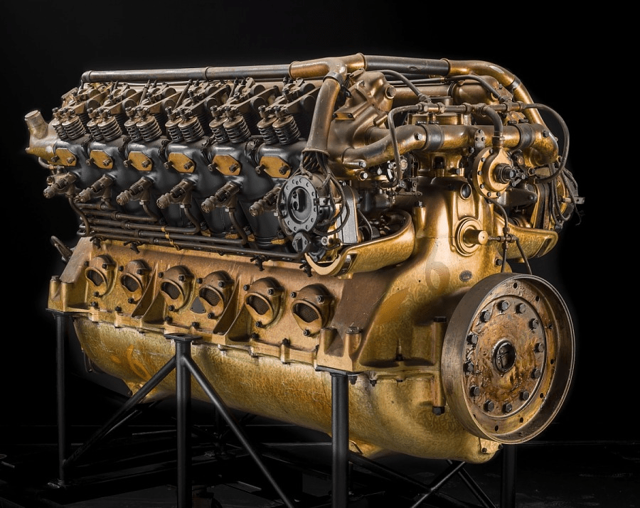
This engine powered the largest airships ever made German Graf Zeppelin, U.S. Akron, and Macon between years 1928 and 1934. It was reciprocating, 12 cylinders, V-type, fuel injected, water-cooled beast – weighting 2,530 lb (1,148 kg). Its power rating was 425 kW (570 hp) at 1,600 rpm Displacement: 33.3 L (2,029 cu in.).
Namely the LZ 127 Graf Zeppelin was powered by five of these monsters, mounted in individual streamlined nacelles arranged so that each was in an undisturbed airflow. Taking the values from above, it makes a total of 2,125 kW (2,850 hp) power output, while weighting almost 6 tons (5,740 kg)! To give you something to compare this with – our family car weights 2.44 t, so this is two of them … and more.

Now let’s welcome our second contestant – AM Racing AMR Dual Stack 250-90 AC Motor.

This baby dates back to 2014 and it is a Liquid Cooled, Permanent Magnet – Remy motor weighting incredible 180 lb (82 kg). It comes with rated torque: 560 lb Ft Peak (w/150 kW controller) and rated power 420 HP peak (w/150 kW controller) Max RPM: 10,000.
Let’s do the same maths as per our lovely Maybach above – taking values from above, our Remy motor sort of matches it based on the peak power value advertised so taking 5 of them as per the Zeppelin configuration. Well 5*180 lb -> 900 lb (410 kg)…. this is 10-times less then the same configuration with Maybachs weighting almost 6 tons (5,740 kg)!
Here comes a huge disclaimer that I am well aware that I am here comparing apples with pears, but I still find it amazing that almost a century later we can achieve same power output with magnitude smaller and lighter technology. Same way it is fascinating what sort of miracles were German engineers to achieve that time.


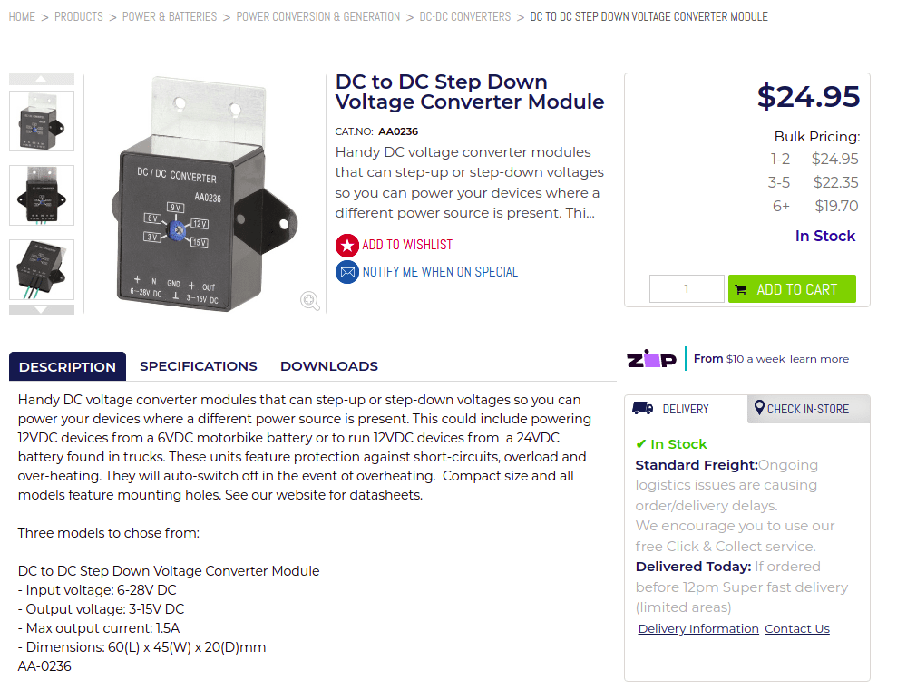
This is a follow up on a previous Power management update article, where I was attempting to reduce number of batteries in our system. Long story short – it didn’t work out as I was hoping for. That DC to DC Step Down Voltage Converter Module I’ve picked wasn’t powerful enough (Max output current 1.5A) to let all servos and ESCs running. Even after doubling it – it wasn’t reliable enough.
So I’ve ended up buying “24V to 12V 10A DC 2 DC Converter Step Down Daygreen Reliable Quality , Newest Type CE Certificated”

.. and also “Waterproof 12V 24V to 6V 3A 18W 5A 30W DC DC Step Down Voltage Converter 12Vdc 24Vdc to 6Vdc Buck Car Charger Power Module”

Both arrived in a good condition and some easy wiring was needed.

I did some minor testing to see that voltages are where they belong.


All seems to be happy! So once again – all ready for Sebi to give it a go! 🙂
Update I: Adding the latest power distribution & controls diagram

I needed Sebi to design something for our friend (I’ll probably make another post about it when having that project finished) and he did it in the OpenSCAD. This came bit as a surprise because Sebi’s been using some different app, which I don’t know … and I am lazy to learn.

Seeing how well he did, I’ve instantly recalled that there are couple things I would still like to improve on our blimp! I’ve recalled that our vectored thrusters ended up just 2D (a rudder), where I planned to get those 3D when having some spare time.
The plan was easy – reuse maximum of what we already have – which is doing well in 2D and insert a new piece between the nozzle and and the vector mount which will be 90o twisted to allow the nozzle to serve as its horizontal stabilisers – elevators.
It worked out perfectly.
Next stage was to slice it and send it to printer and in couple hours we’ve ended up with a quite interesting setup.


I mounted both servos and Sebi did all the wiring, using one of his spare Arduino Mega and joystick.


Bit of coding from Sebi.
#include <Arduino.h>
#include <Servo.h>

Servo servoX, servoY;

auto potX = A0;
auto potY = A1;

void setup() {
  servoX.attach(2);
  servoY.attach(3);
}

void loop() {
  servoX.write(map(analogRead(potX), 0, 1023, 45, 135)-10);
  servoY.write(map(analogRead(potY), 0, 1023, 45, 135)+5);
  delay(20);
}
It actually needed some more “love” to polish all the surfaces properly to make all movements smooth, but it worked out perfectly!
Hope you like it too!
Now we need to prepare a second one, mount those on our blimp and add all the elevator logic in there! 🙂
This is a follow up on an original article Testing Rig Upgrade, as it just keep going!
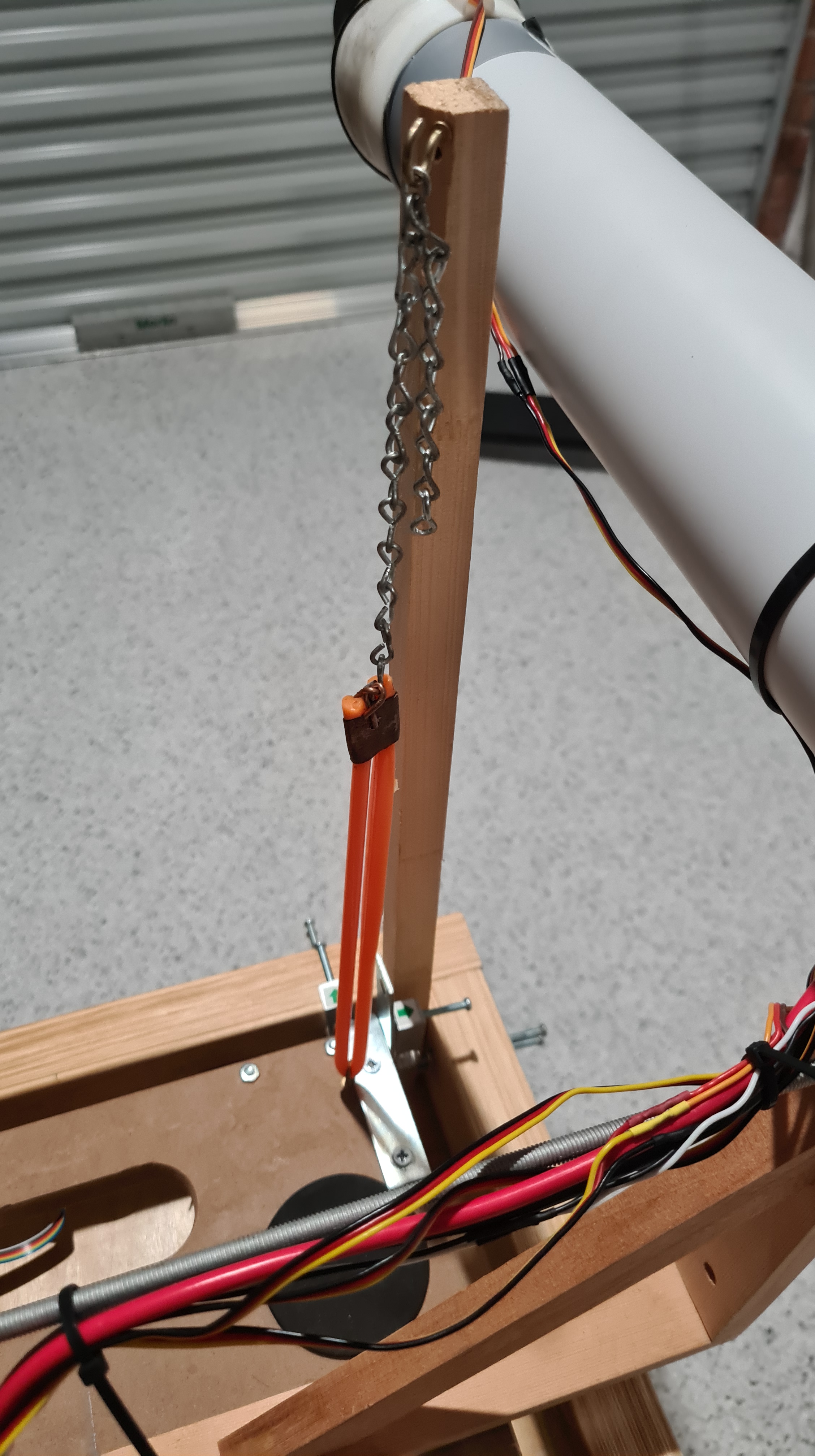
Ad the first thing, I have to admit that those rubber-bands were not good enough. I’ve left our model hanging there for a week and they got loose (with a great help of Queensland summer temperatures as well). So they’ve got replaced by springs.
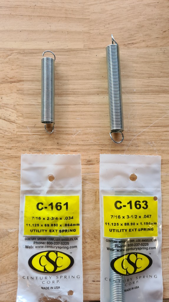
You may wonder why two types … because that C-161 wasn’t strong enough, so I had to upgrade to C163s! All values below are in imperial units – but I suppose it is clear C163 are almost 3-times stronger than those C161s.
| Part Number: | C-161 |
| Manufacturer: | Century Spring |
| Ajax Part Number: | 50161 |
| Spring Type: | Extension |
| Material: | Galvanized Hard Drawn |
| Wire Size: | 0.035 |
| OD: | 0.437 |
| OAL: | 2.750 |
| Body Length: | 1.875 |
| Max Ext Length: | 5.900 |
| Spring Rate: | 0.5 |
| Max Load: | 3.3 |
VS.
| Part Number: | C-163 |
| Manufacturer: | Century Spring |
| Ajax Part Number: | 50163 |
| Spring Type: | Extension |
| Material: | Galvanized Hard Drawn |
| Wire Size: | 0.047 |
| OD: | 0.437 |
| OAL: | 3.500 |
| Body Length: | 2.626 |
| Max Ext Length: | 3.600 |
| Spring Rate: | 2 |
| Max Load: | 8.4 |
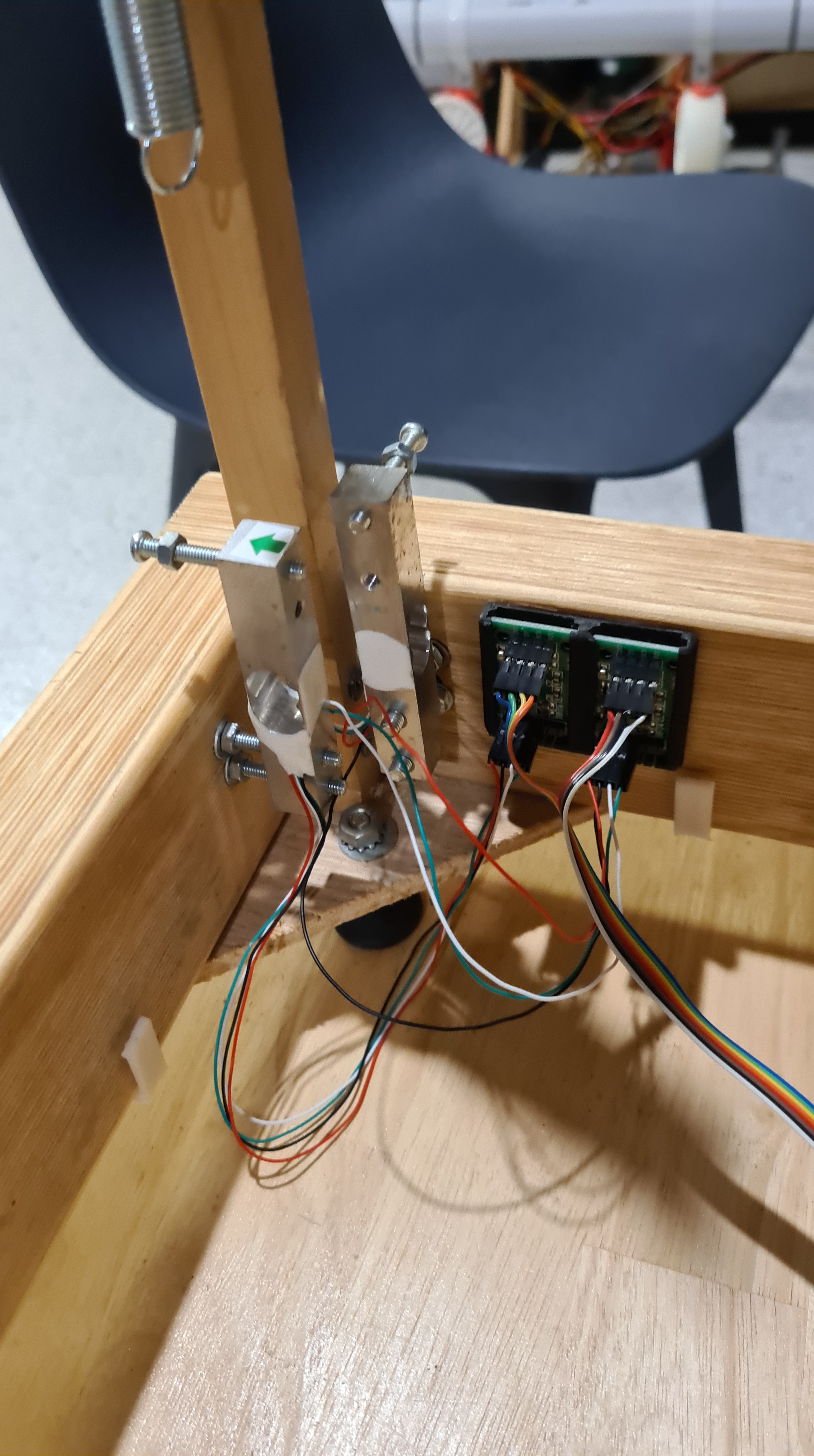
In a next stage I’ve decided to somehow reorganise all the wiring and amplifiers, so they are all not hanging there in the air. That already proven being a bad idea as I’ve damaged couple of those cells in a irreparable way.
The first was a set of load-cells clamps.

Their design was quite trivial.
module pcb_cutout(z) {
  T(z,0,2)
  cube([21, 2.3, 39], center=true);

  //space for pins etc.
  T(z,3,2)
  cube([18, 12, 37], center=true);

  //slide for a chip on a side
  T(z+9.3,1,2)
cylinder(39, d=3, $fn=3, center=true);
}

D() {
  union() {
    //pbc + meat
    Ty(-1)
    minkowski() {
      cube([45.2, 3, 36], center=  true);
      sphere(2);
    }
  }

  //pbc cutout
  pcb_cutout(-12);
  pcb_cutout( 12);

  //holes
  hole_size = 3;
  T(12, 0, 1)Rx(90)
cylinder(15,d = hole_size, center = true);
  T(-12, 0, 1)Rx(90)
cylinder(15,d = hole_size, center = true);
}
And they come up nicely.


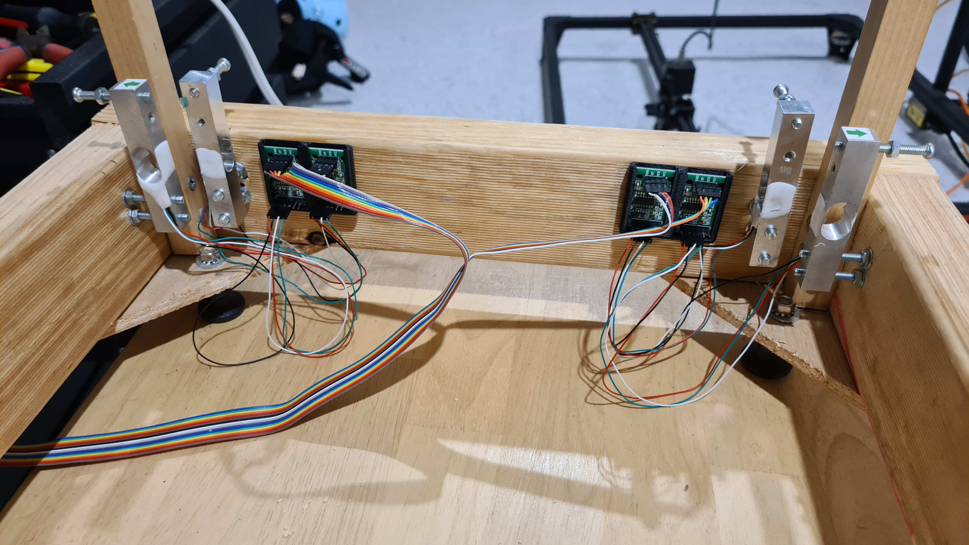
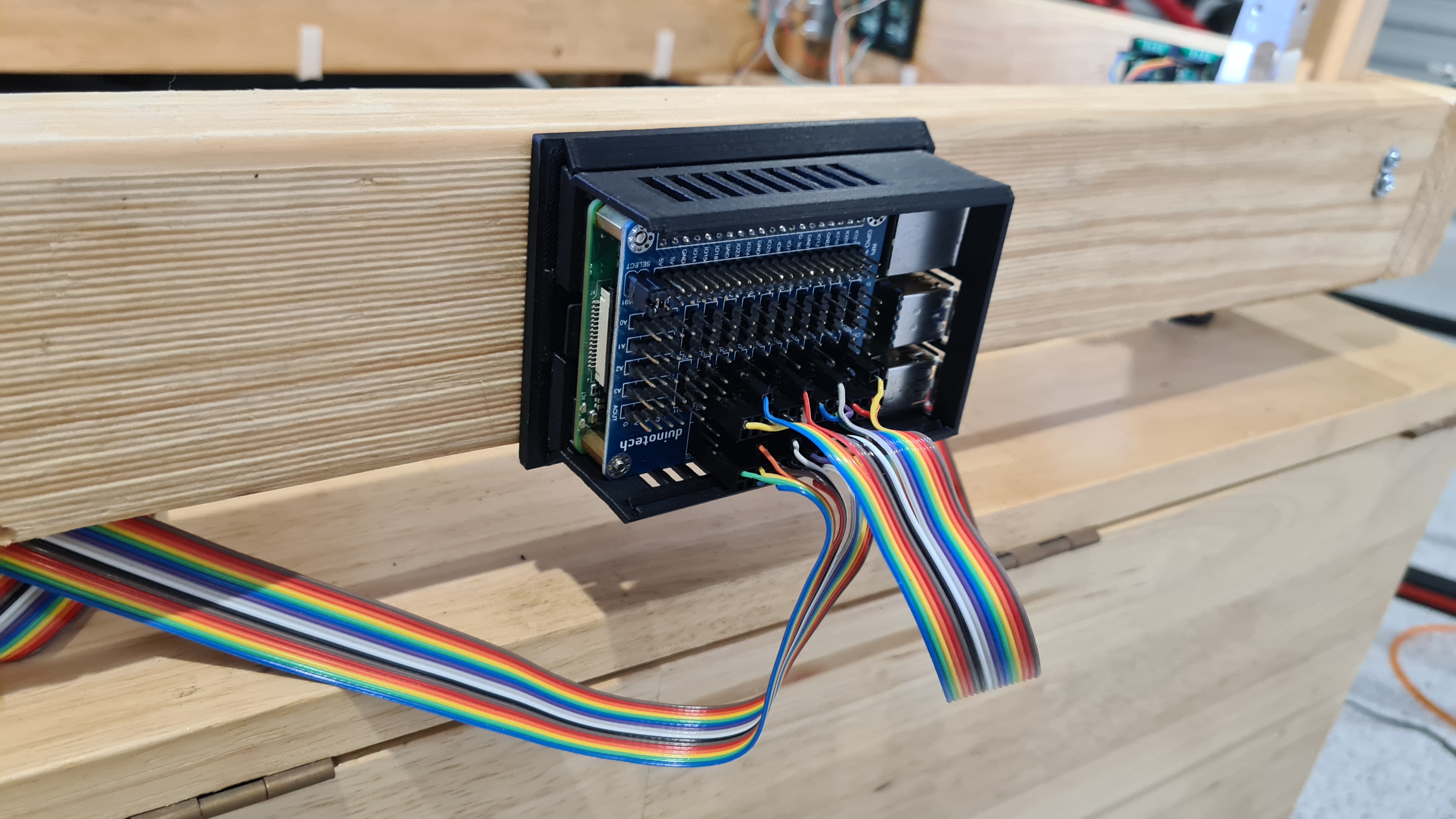
Well, rainbow data cables needed some clamping as well. I’ve printed a set of very simple L-shapes to hold those well.


Another step was to get some nice box to hold our RaspberryPi. I’ve been lazy to start designing it myself so I’ve simply downloaded Raspberry Pi 4 Case, active cooled with wall mount from someone with nickname tipam and which looked pretty cool on a picture.

Mainly it came with a promise of a wall – mount, which honestly needed some more love and I actually ended up tweaking it myself to fit the testing rig beam. It all still worked out very nicely.


Final touch was a set of screws to reduce a surface area between the load cell and our cart. Serge sharpened them for me and here they come mounted.


Then I spent three weeks developing an app which would visualise readings from all those load cells.
I’ve subscribed to Martin Hill’s videos couple years back – he does amazing stuff – while now he posted his two latest from 22 March 2022, which are showing some awesome details.
First video is from a cam on board of his blimp, when watching, don’t forget to notice voltage (10V) and current (1.* Amps) values in upper right corner!
The second video appears to be from the same flight, but from the Ardupilot perspective – following predefined navpoints.
Well so this is amazing & well done Martin Hill! I wish we’ll be posting something very much similar with our BBBlimp project any time soon!
UPDATE 4th April 2022
Sebi told me that when presenting those Youtubes I’ve forgot one showing parts of the actual blimp flight. Thank you Sebi & here it comes!
This is going to be an unusual post – a book review of the Fatal Flight – The True Story of Britain’s Last Great Airship By: Bill Hammack!

But let’s start from beginning. Quite a while ago I’ve contacted Jesse Krizik from US, a real actual man owning the http://krizik.com/ domain! It is not a typical me to keep contacting random people, but it all got motivated by a story of František Křižík – a Czech’s Thomas Alva Edisson. I was simply elaborating about some different name for our project and following inspiration on Tesla, Nikola etc. Krizik seemed to be giving a pretty good foundation.
Anyway, Jesse came back almost instantly, quite surprisingly saying that this is an amazing coincidence that he’s just reading a book from Bill Hammack on a fate of one of the largest airships ever built. I couldn’t resist and ordered one from the Australian Booktopia. I didn’t know that such a service exists, but they printed it out for me on-demand and send me my-own copy, in an excellent shape and quality. Book arrived in a week and I sent following picture to Jesse to thank him for suggestion.

I hope it is not getting too boring, so let’s get back to the main story here. The book is written by Bill Hammack who an American chemical engineer, and Professor in the Department of Chemical Engineering at the University of Illinois at Urbana–Champaign. I never heard about him before getting a word from Jesse. Bill runs a technical series on Youtube and he has a gift to bring engineering principles to masses. I strongly recommend reading about him, going through his bibliography and watch his Youtube channel.
The book finally! Let’s say it that first 186 pages is a readable compilation of the R101 story from many sources, many of those never published before, with a nice touch of an artist to make it more acceptable (less boring) for today’s audience. Amount of “beef” varies chapter by chapter, quite likely correlating with information density of original sources. I understand that technical author can’t make up things to keep the pace, but this is perhaps my only critique to this book – some areas simply stand out how detailed they are (an engineer climbing a ladder, dinner menu), while standing next to the others where similar details would be appreciated (airship design history, building, multiple other test flights, aftermath).
But enough of that – it is how it is, Mr. Hammack clearly builds up a fascinating picture of one of the flying legends. Think about this book as a historical episode of the Seconds from Disaster TV show. With every page unfolding you are just getting better and better understanding why this amazing project ended up like it did.

I wonder, does documentaries work with a concept of “spoilers“? I suppose they don’t, but I still won’t go in too many details, but still let me present few interesting notes I made for myself.
As the first thing, I loved all Bill’s schematics in the book. As they are clearly saying “do not copy” I’m putting here just one – the Crew & Passenger decks and meanwhile I’ll ask Mr. Hammack to check if that’s ok.

Wikipedia intro: R101 was one of a pair of British rigid airships completed in 1929 as part of a British government programme to develop civil airships capable of service on long-distance routes within the British Empire.
Finally, the appendix called just “Notes”. Every its line, just a treasure, while the note #24 took me completely by surprise.
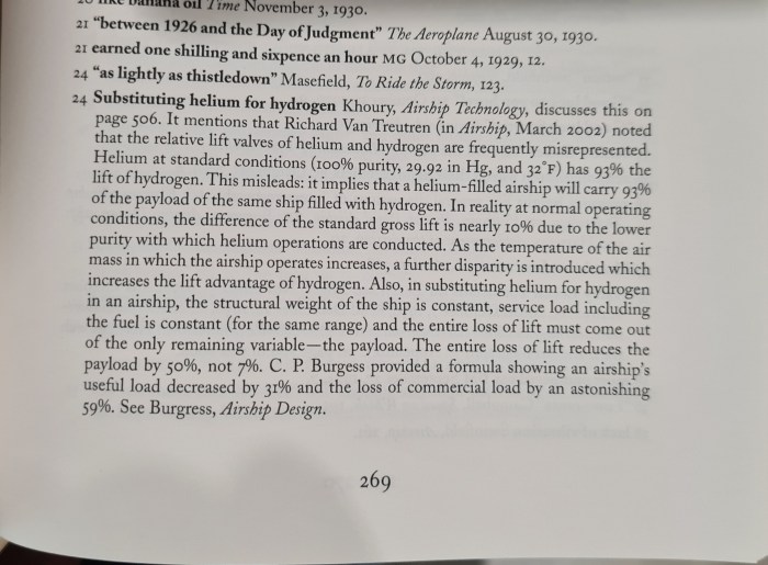
Yes, what it says is that when comparing the relative lift valves of helium and hydrogen – the difference (loss) of commercial load of the helium airship is incredible 59% to the hydrogen one! I suppose I am very much biased here by our hydrogen airship project, still I find it amazing to find such a strong supporting claim.
Yes, I’ve instantly ordered the Airship Technology by Khoury from Booktopia. Let’s see if it is really there! 😀
Update I. (21st March 2022)
As a reaction on this review I’ve received a comment pointing to a song from Iron Maiden (which is not usually on my daily playlist) called “Empire of the Clouds”. Quite surprisingly this song is wrapping the faith of our R101!
Mist is in the trees, stone sweats with the dew
The morning sunrise, red before the blue
Hanging at the mast, waiting for command
His majesty’s airship, the R101
Iron Maiden – Empire of the Clouds
Hysata company from Wollongong NSW, claims that their electrolyser can produce Hydrogen with a total efficiency of 95%!
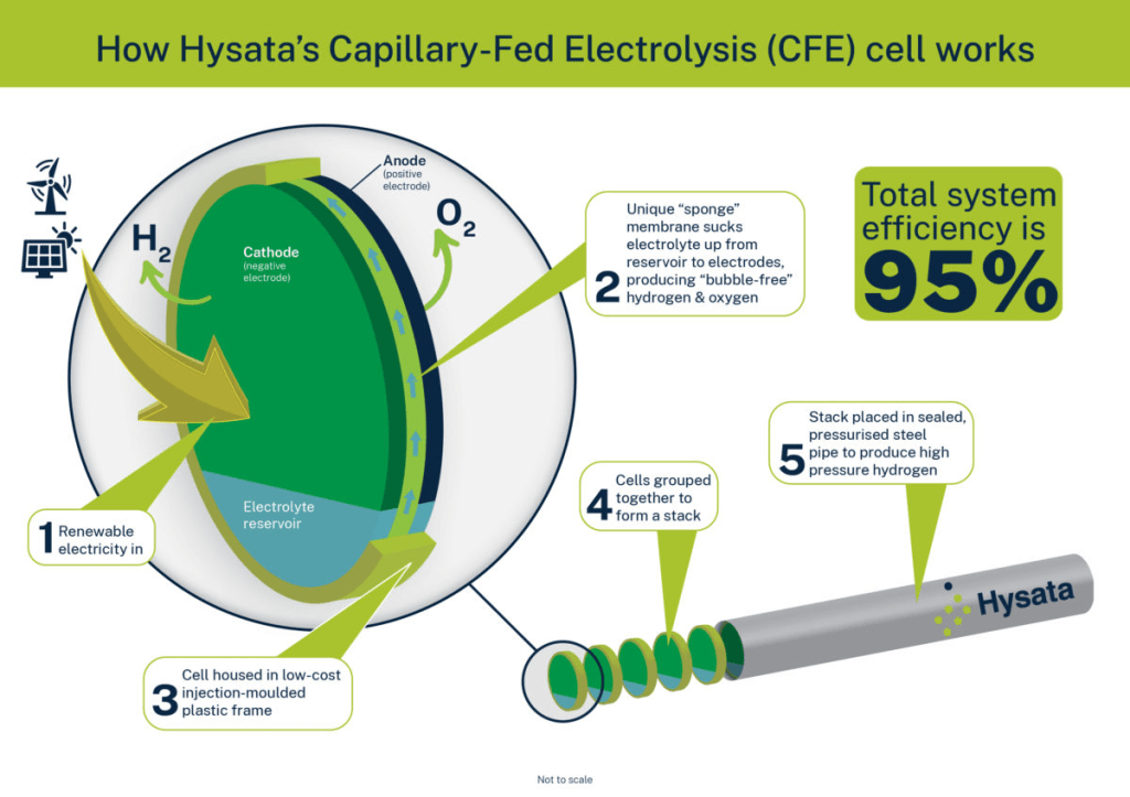
Why 95%? 95% efficiency would mean that a green Hydrogen can be produced for less than $2 AUD per kilogram (it was $20 per kg last time I was getting it from BOC a year ago). More details here.
While working on many other things (testing rig, burned servos replacement, laser cutter, CP tube jig … ) Martin sent me this awesome video made just recently for BBC – Thank you Marting – and you all enjoy! 🙂
Edit: As I’ve been sending it all around with my comments, Murray have been able to summarise whole story in one simple sentence, which I really liked:
100% agree with the point that after the Titanic we didn’t give up on ships!
Murray
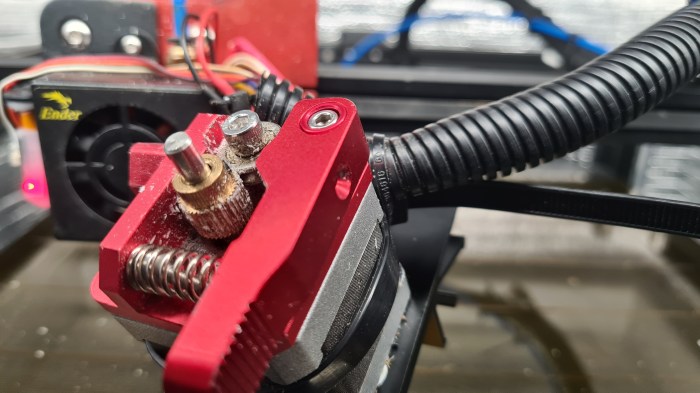
I’ve got few failed prints lately, well little bit more than usual. So I blamed our garage not providing too stable conditions through the Queensland summer first, while did a bit of check on the printer condition and found the brass drive extruder gear wheel being bit worn out too.
It took few moments to order a set of new ones from eBay.

… and then 3 weeks to get them delivered.
Comparing a new one with the old one – there was not too much difference. Yes the old one looked bit used, but I don’t think it was nothing too serious to prevent it doing it job.

While having it all in pieces, I’ve cleaned up all relevant parts and did some tightening to get it ready for another printing marathon.
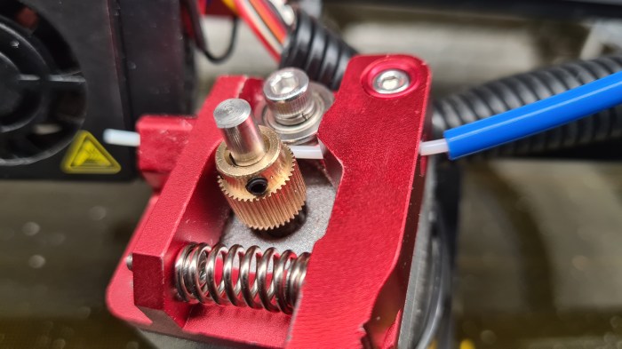
Looks good, doesn’t it? 🙂

It is hard not to bump in some very interesting people, when walking around with an hydrogen airship project. So I’ve ended up being introduced to Mr. Murray Shearer a head of Hydrogen and Alternative research from Central Queensland University.
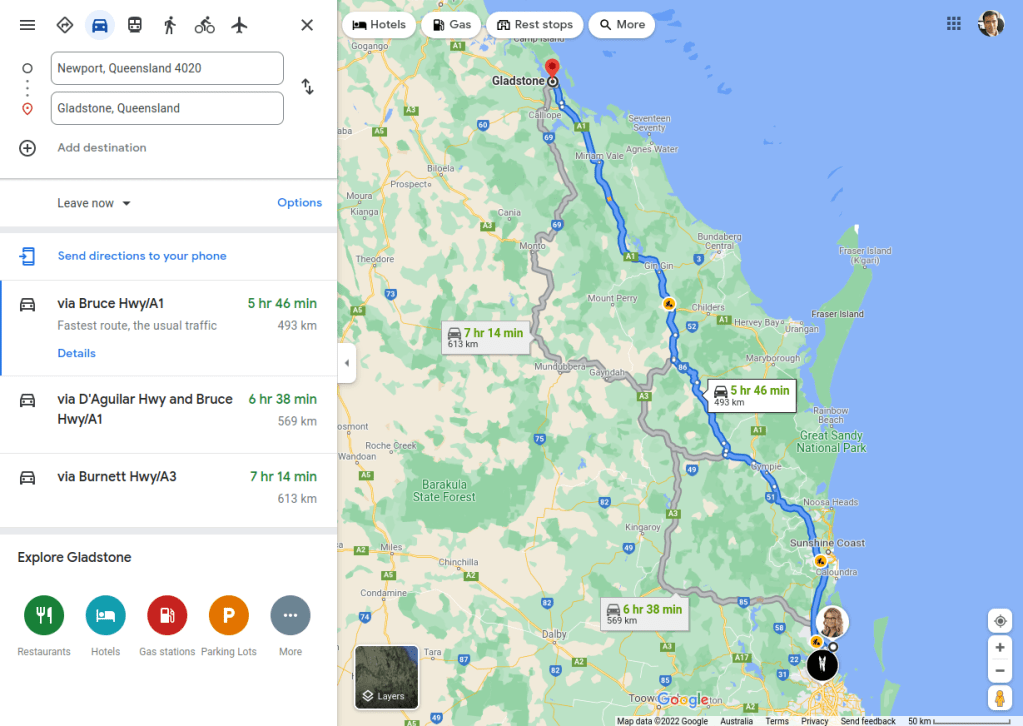
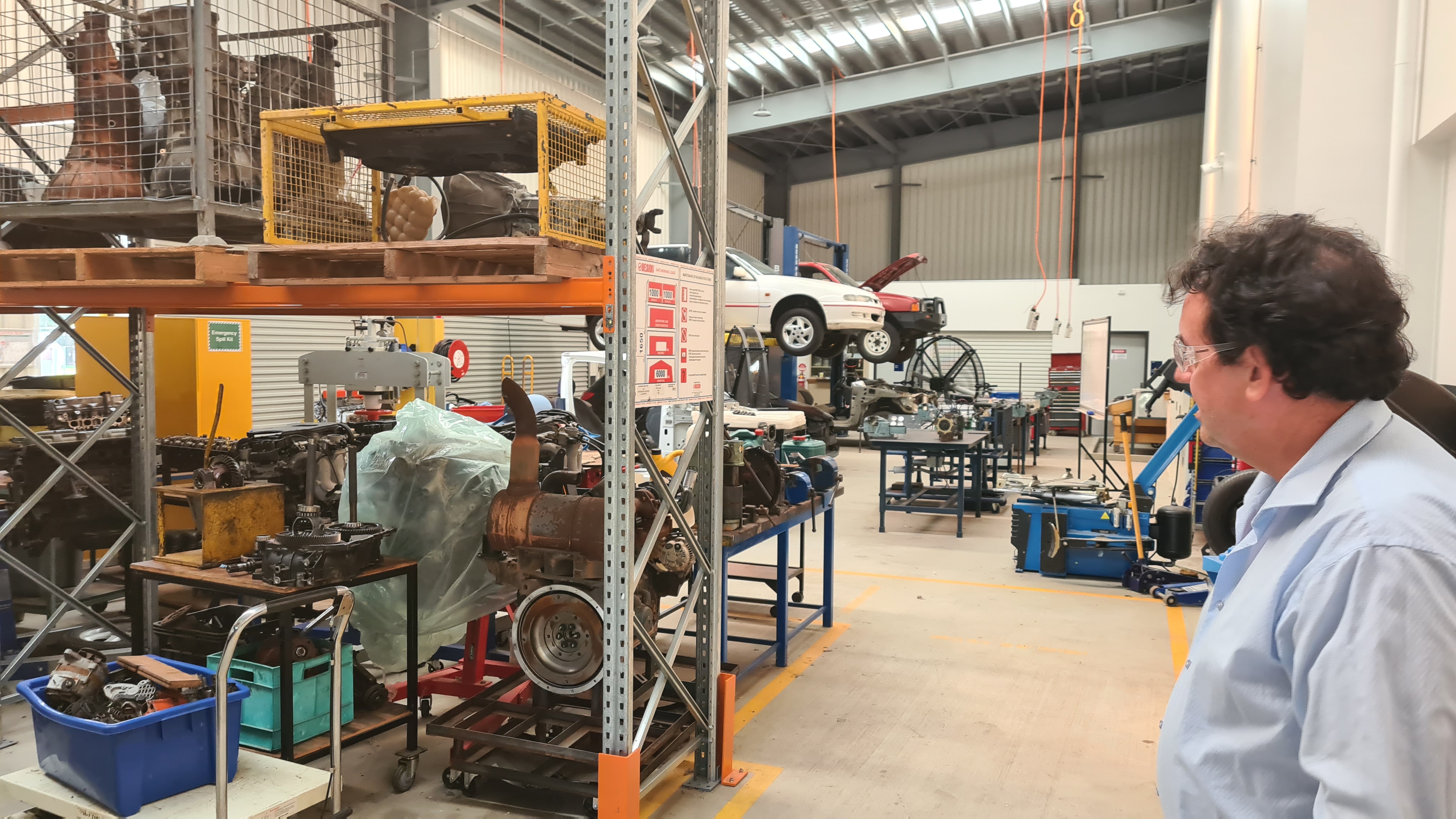
After several calls and missed opportunities things worked out that I had a somehow a trip around one of the CQU’s departments – the one in Gladstone.
I had an great time chatting with Murray for couple days there, including an exclusive tour over the uni campus. Our main topic was our hydrogen airship project and I couldn’t resist and told Murray everything, including a practical demonstration of our jet-cart.

It has to be something mysterious with these live demonstrations, that things usually don’t go as planned. Well it wasn’t different this time when one of our front propellers got loose/stuck in the moment of the highest performance and ripped off one of front intakes with pretty spectacular acoustic effect.
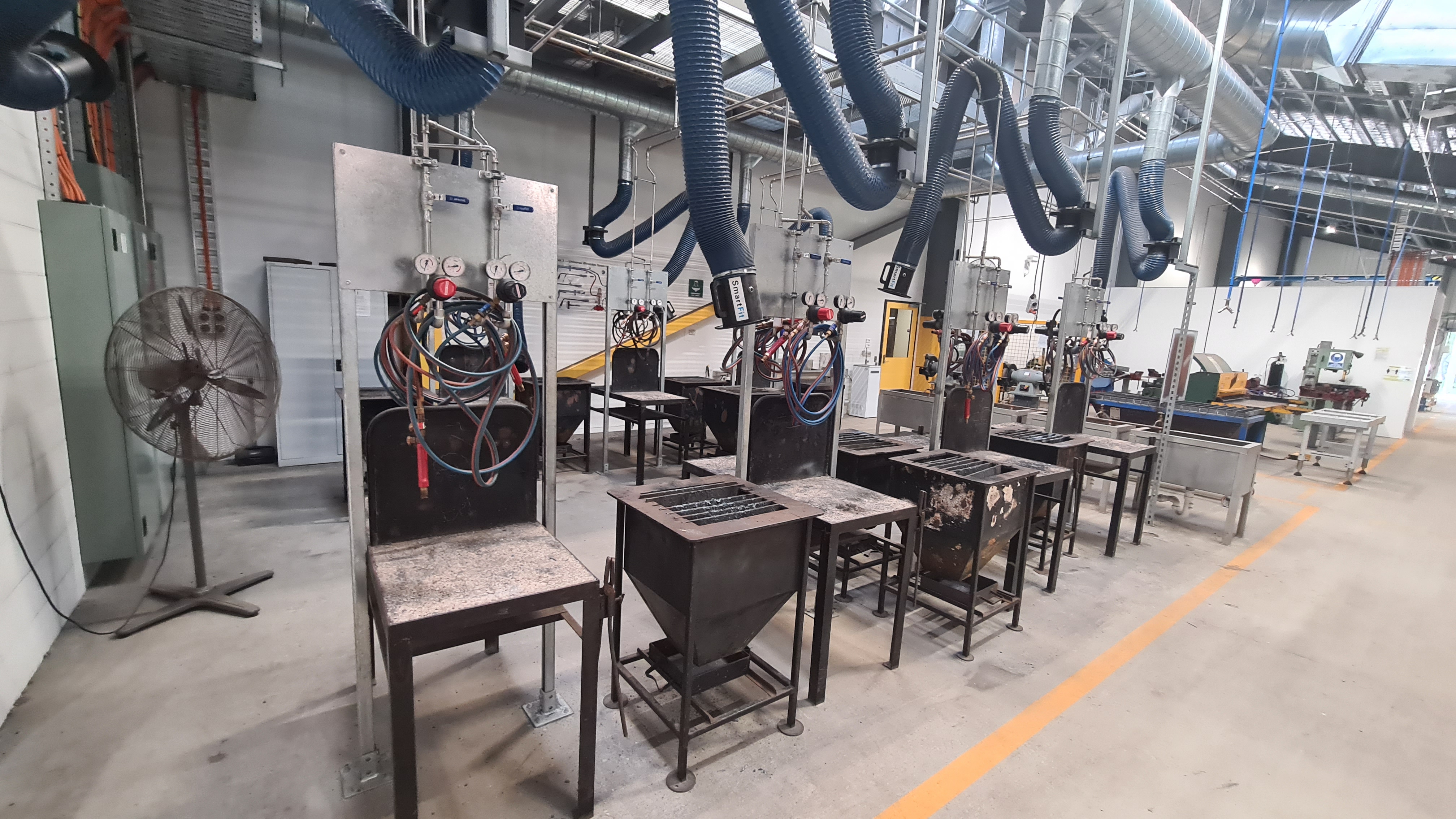
Luckily it was after our main demo and also it looks like Murray’ve seen things like that before (he holds a doctorate in explosions). Anyway, next day we did an excursion over the campus to check on some of its potential. I took several pictures to have some good material for our blog readers.


Huge thanks to Murray for this opportunity – it was awesome in many ways and I really enjoyed all my stay there. Hopefully we’ll have a chance to catch up soon again!
I am in touch with the Coding from Beach team for years – Ben, Ric, Chris, the other Chris … .

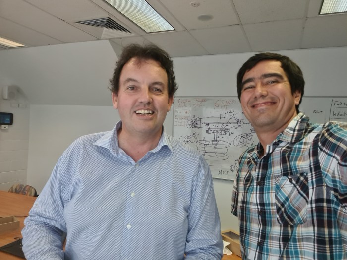
So we went with Sebi there yesterday (4th Feb 2022) and presented our current project status and it was fun. As you can see on faces below – everyone got amused and we’ve got plenty of interesting questions on what, how and where next.
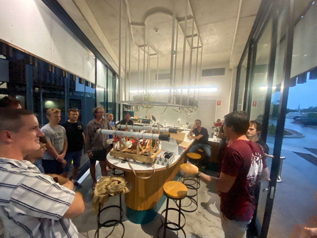

I was excellent to get feedback from you guys – as always. Thank you for your hospitality and giving us a chance to present our project!
Our plan to have a proper testing rig for our airship controller got hit by several issues. First – as it wasn’t the first priority, there was always a reason for not progress on its development. Second those rubber-bands I envisioned to keep it flying haven’t been reliable enough.
On a picture below you can see how that rubber rips in pieces when confronted with its copper wire attachment.
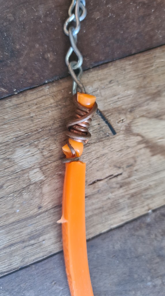
Thinking about it for a while I came with a plan to reuse some old copper tubes to create some more solid attachment mainly employing more surface together with doubling amount of rubber involved. As always I took few pictures to at least briefly document that process.

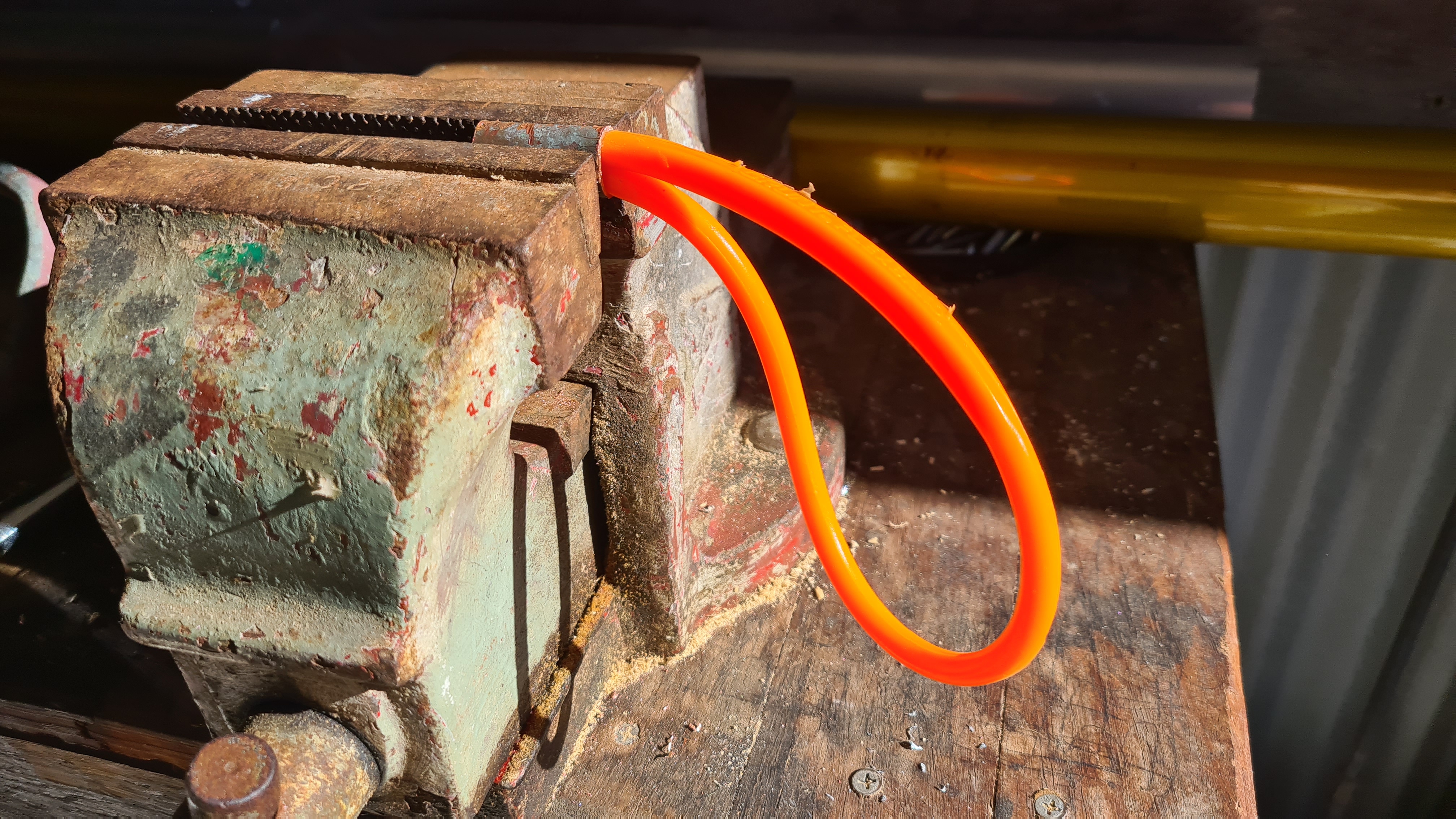

What’s not on pictures is that I’ve ended up struggling to push both rubber ends through that copper ring. Some really old memory of my father came with an idea of using just a common hand-soap to help it a bit and that did the trick! Thanks daddy!
Anyway, Sebi couldn’t resist to give it a proper go. 🙂
Sebi demonstrates power of all motors combined, so don’t forget to stay to the end! As always, let us know your ideas, any constructive comments are always welcome! 🙂
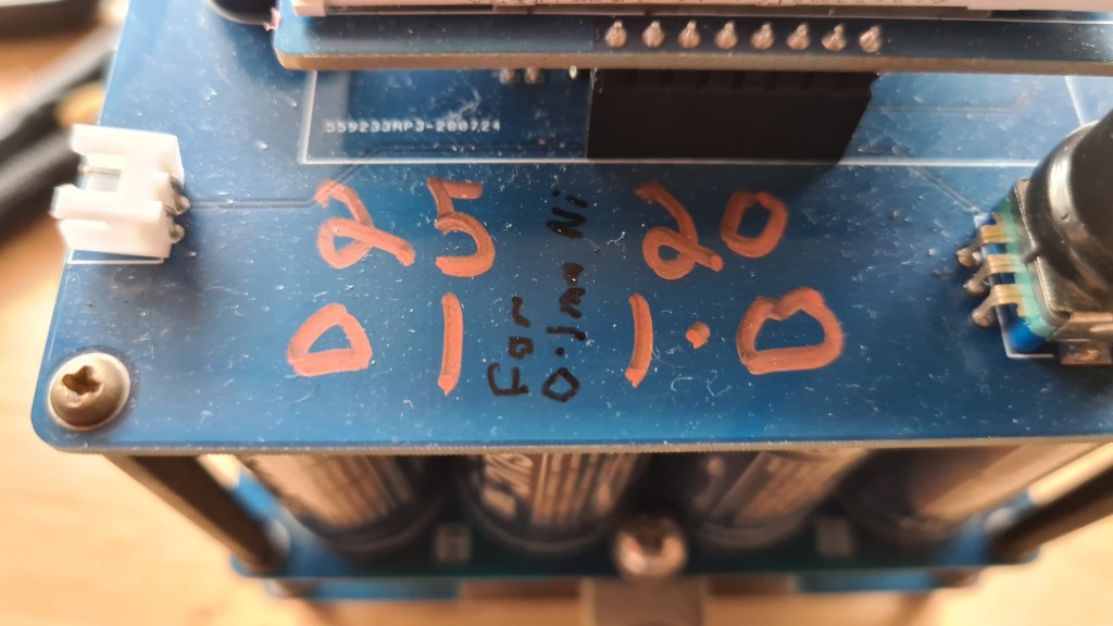
Progressing with our controls development we’ve ended up with a “too many batteries” dilemma. I’ve captured our current situation on a diagram below.
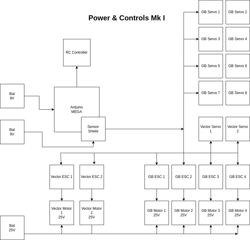
As you can see it we currently need our “big fat” 25V battery + couple of 9V batteries to feed Arduino MEGA + its Sensor Shield.
Situation got out of control when we are now adding BeagleBone Blue and GPS shield to the whole scope. Luckily Richard told me about an option to move in a DC to DC converter to reduce number of batteries to the main one (at least for now till we’ll need to have BBB on its separate power rail).
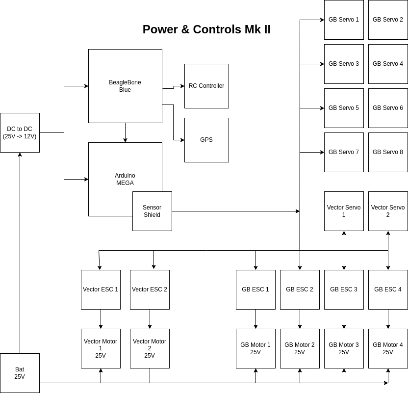
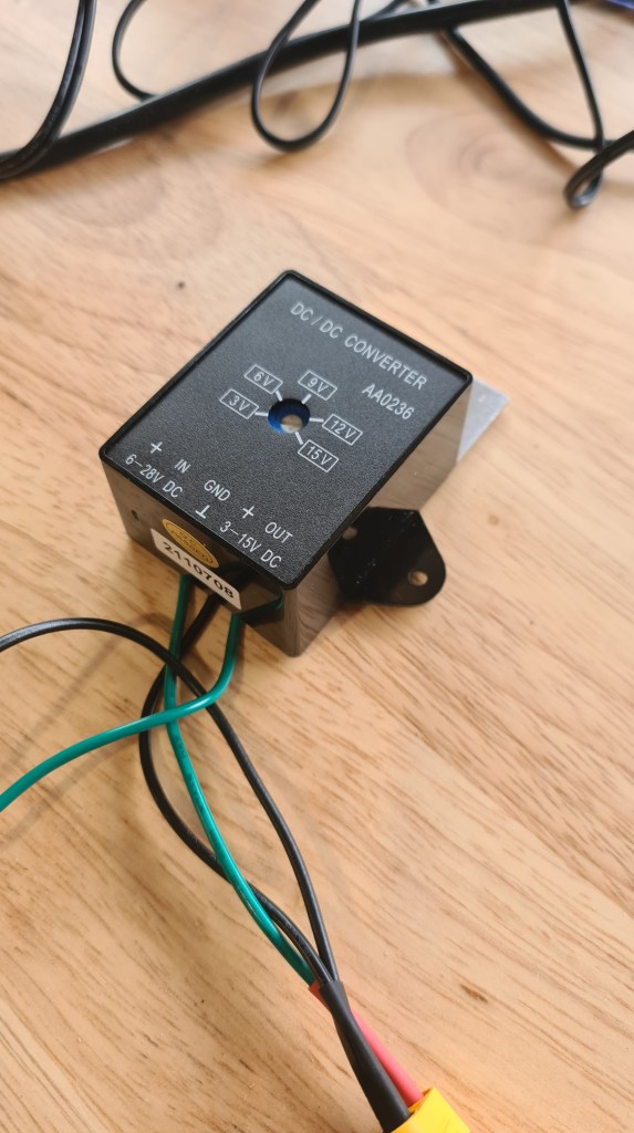
Local Jaycar provided suitable DC to DC Step Down Voltage Converter Module.
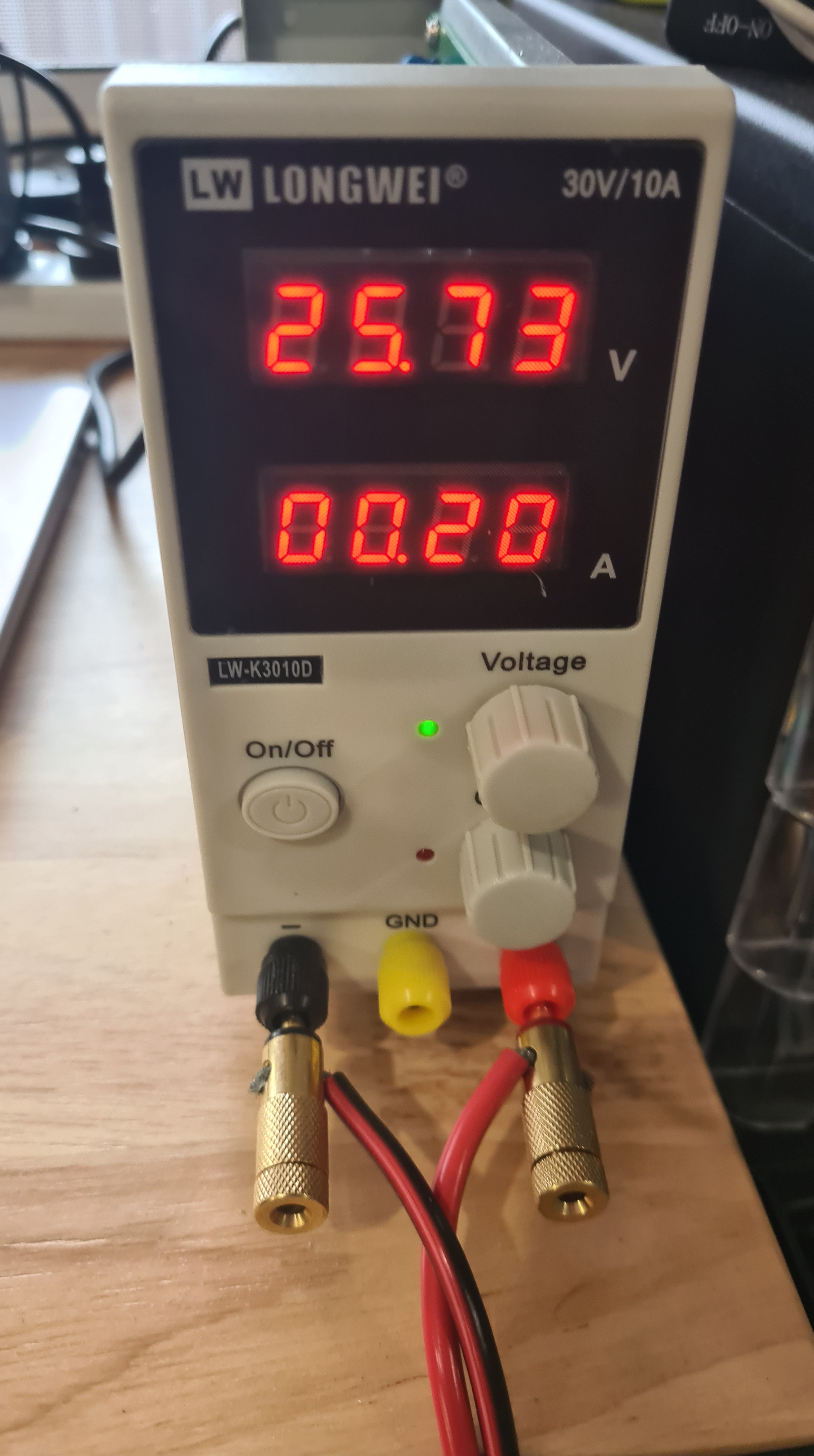
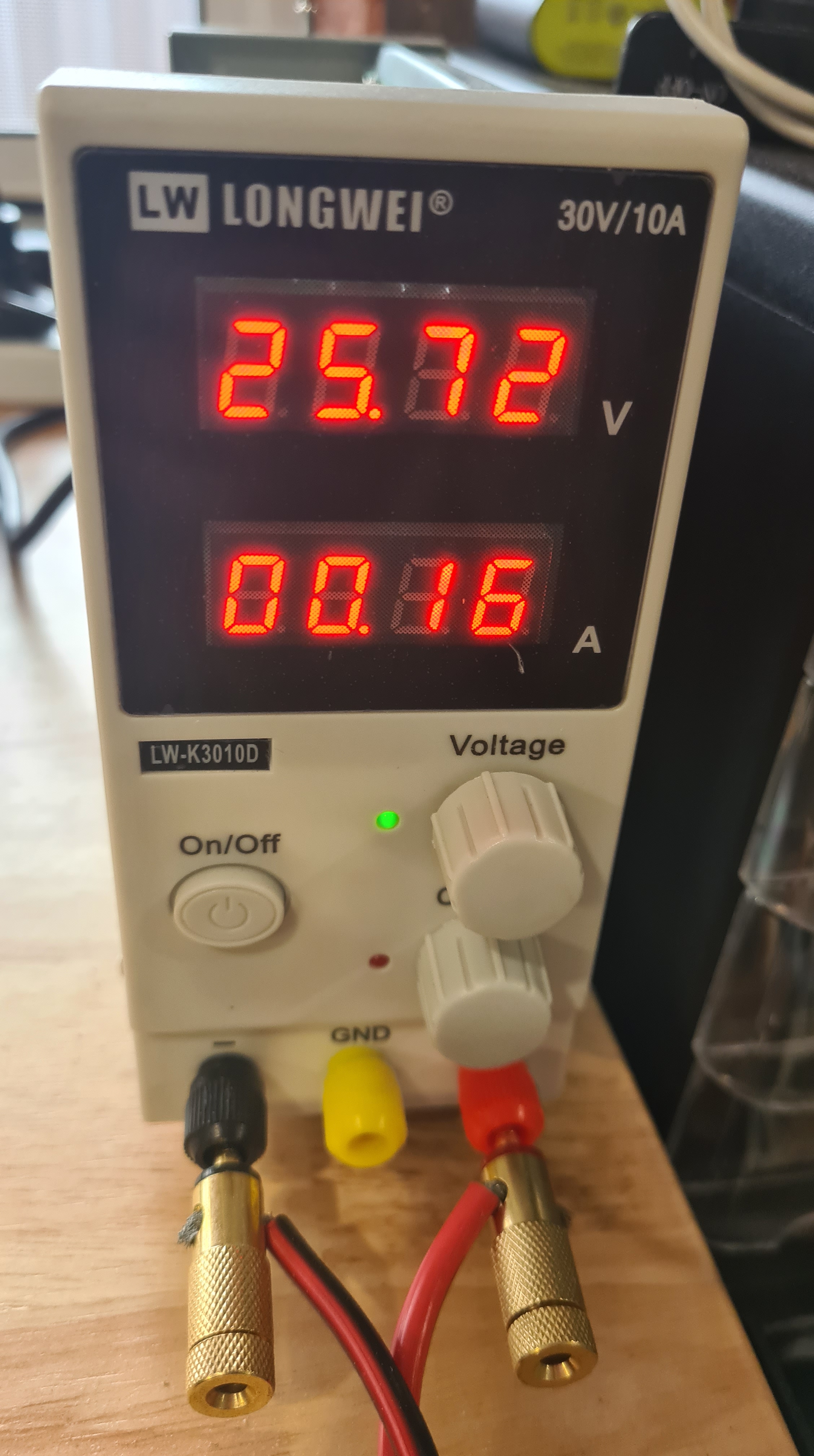
.. and I did some testing with it before hooking it up. As you see on the picture below, I am using our power supply to feed in 25V and our multi-tool detects 12V on the output.
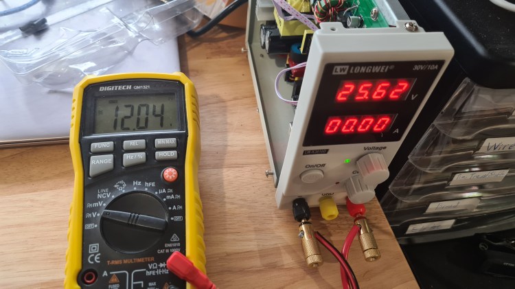
It looks pretty nice, doesn’t it?
At the end I hooked it up to BBB and to Aruduino with all servos / ESCs / RC receiver / GPS powered up and it came with drawing roughly 0.36A altogether. That should do!
Finally – it is all mounted in. On a picture below you can see cables connecting our main power bridge (blue and black) going in the DC to DC converter and than from there in the Arduino MEGA.
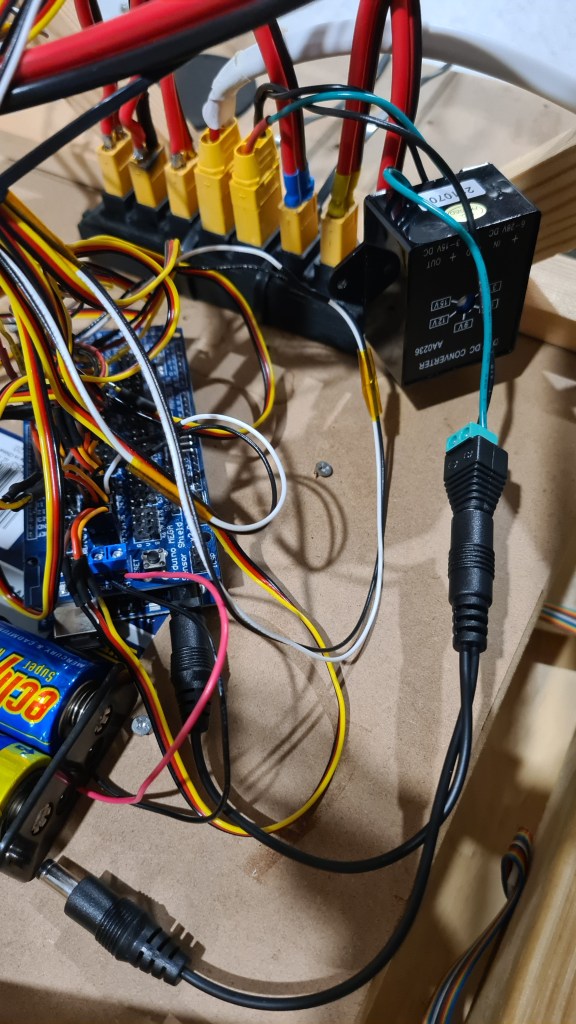
We did some preliminary testing with Sebi and it might be that that Sensor Shield draws more power than that DC 2 DC can provide, so it is hard to say if this is a final solution. Well, stay tuned and fingers crossed!
ArduPilot is an open source, unmanned vehicle Autopilot Software Suite.
This is the tutorial I am using to set up ardupilot on the beaglebone blue: https://github.com/imfatant/test
We are using ardupilot because we saw a youtuber by the name of rctestflight using it and it looked like it worked well(and it does).
In order to edit the ardupilot config access this file /etc/default/ardupilot also other settings are changeable in the file here: (for example console should be linked with the GCS’s (Ground Control Station’s) ip address) http://ardupilot.org/plane/docs/parameters.html?highlight=parameters
Other possibilities exist, namely:
Switch -A  -->  "Console", SERIAL0, default 115200
Switch -B  -->  "GPS", SERIAL3, default 57600
Switch -C  -->  "Telem1", SERIAL1, default 57600
Switch -D  -->  "Telem2", SERIAL2, default 38400
Switch -E  -->  Unnamed, SERIAL4, default 38400
Switch -F  -->  Unnamed, SERIAL5, default 57600
Also, keep in mind that in order to connect with GCS the beaglebone blue will need wifi do this through the connmanctl. A problem sometimes is that the wifi is disconnecting I fixed this by connecting my own antena.
This file exists just in case you need to change some settings: /usr/bin/ardupilot/aphw
Lines 5 to 7 of the file switch on power to the BBBlue’s +5V servo rail – i.e. for when you’re using servos. Not necessary for ESCs.
Line 8 enables the PRU(programmable real-time unit). https://beagleboard.org/pru
To get ArduPilot going, choose which flavour you want and type ONE of these: (I have changed this process on my beaglebone blue)
sudo systemctl enable arducopter.service
sudo systemctl enable arduplane.service // no executable
sudo systemctl enable ardurover.service
sudo systemctl enable antennatracker.service /// no executable
After you reboot, your ArduPilot should inflate automatically. Look for the flashing red LED!
It’ll help to familiarise yourself with systemctl (https://www.freedesktop.org/software/systemd/man/systemctl.html). Some useful example commands:
sudo systemctl disable <name of service>
sudo systemctl start <name of service>
sudo systemctl stop <name of service>
Just in case the ArduPilot parameter settings files: /var/APM/{ArduCopter.stg,ArduPlane.stg,APMrover2.stg,AntennaTracker.stg}
I start my ardupilot through a .sh file, all it does is it calls the executable with the right parameters, this is where you should change the ip. ardupilot.sh
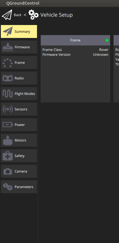
Download either Mission Planner (http://firmware.ardupilot.org/Tools/MissionPlanner/MissionPlanner-latest.msi) for Windows or QGroundControl (http://qgroundcontrol.com/) for Linux & Windows. Both these programs will connect to streams of MAVLink data coming over the network (via UDP on port 14550, for example) or over COM ports.
If you’re having difficulty establishing a link, look at the following:
To make sure you are doing it right this is my setup of connections also I am using the em-506 GPS and a simple reciever with ppm connected to the 3v3 and gnd and the sbus pins on the bbb like so:
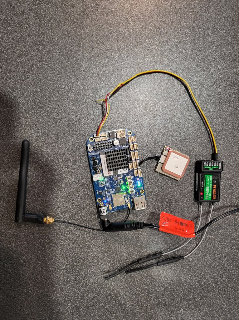
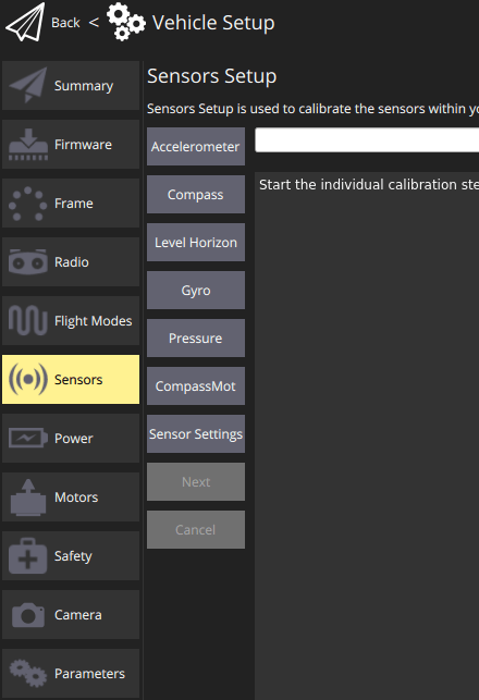
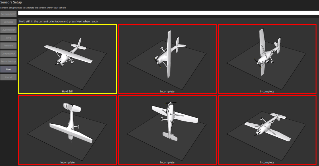
After that open your GCS’s software and it should automatically connect with your computer. When I first started up the software I needed to calibrate some of the beaglebone’s sensors so if there are any difficulties consider re-calibrating the sensors.
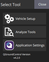
You can re-calibrate by going onto your GCS: mine is QGroundControl; click on the top left icon, click on your sensor. and then follow the prompts to re calibrate.

I have also added this command: sudo ./ardurover -C /dev/ttyO1 -A udp:192.168.0.191:14550 -B /dev/ttyO2 -F /dev/ttyO5
To run on startup because the services aren’t working for some reason: you can edit it with this: sudo crontab -e
Oh and this command aswell to power the power-rails: ./usr/bin/ardupilot/aphw
At the end all I need to run ardupilot is to ssh to my bbb and then run the ./ardupilot.sh script.
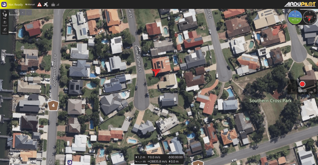
If all works in the end you should end up with a red flashing led on your bbb and a neat looking ardupilot GCS.
As per our yesterday’s post – our initial GPS accuracy test was horrifying. So I discussed this with Andrew and he suggested to give it a go with something more sophisticated like gpsd — a GPS service daemon. It took just a moment to set it up on our BeagleBoneBlue as gpsd is one of commonly supported packages on Linux.
debian@beaglebone:~$ sudo apt install gpsd
[sudo] password for debian:
Reading package lists... Done
Building dependency tree
Reading state information... Done
gpsd is already the newest version (3.17-7).
0 upgraded, 0 newly installed, 0 to remove and 1 not upgraded.
Then we hit a bit of trouble when installation actually starts the gpsd daemon on its own and there’s been a conflict on sockets, but couple of systemd commands sorted it out.
debian@beaglebone:~$ sudo systemctl stop gpsd
debian@beaglebone:~$ sudo systemctl stop gpsd.socket
And finally we’ve been ready to launch it.
debian@beaglebone:~$ sudo gpsd -D 5 -N -n /dev/ttyO2
Now querying it with telnet on socket 2947 comes with nice “welcome” message.
debian@beaglebone:~$ telnet localhost 2947
Trying ::1...
Connected to localhost.
Escape character is '^]'.
{"class":"VERSION","release":"3.17","rev":"3.17","proto_major":3,"proto_minor":12}
Next stage is to enter “?WATCH={“enable”:true,”json”:true};” to set gpsd to the observing mode and start us feeding back.
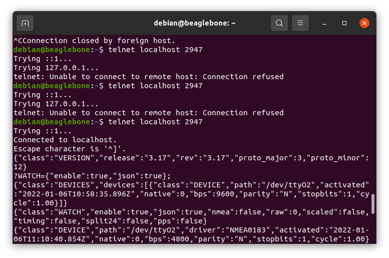
I’ve left it running for few moments and picked random message like this:
{"class":"TPV","device":"/dev/ttyO2","mode":3,"time":"2022-01-06T11:12:21.000Z","ept":0.005,"lat":-27.205174468,"lon":153.094770215,"alt":0.258,"epx":20.312,"epy":16.881,"epv":87.471,"track":261.5038,"speed":0.170,"climb":-0.049,"eps":40.62,"epc":174.94}
There you can see information in a much nicer (human readable) form which gave us coordinates like: “lat”:-27.205174468,”lon”:153.094770215 and that thrown us to our neighbours!
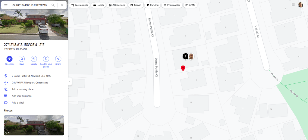
Seeing how those values were fluctuating, we went out with Sebi and did one more measurement in front of our house.
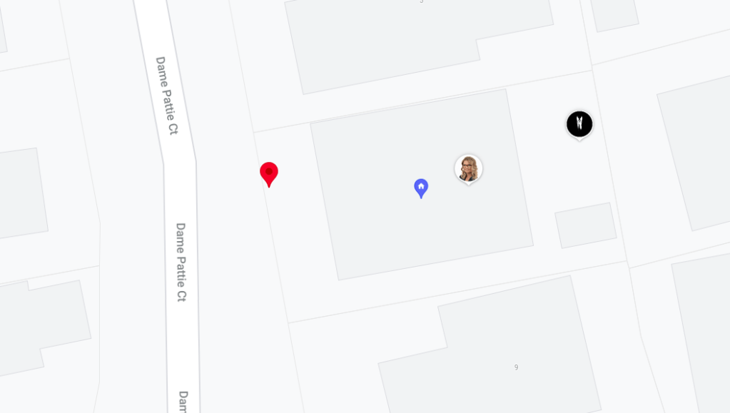
That went spot on! I think it was like about a meter from us. That’s what we needed. Next step – telling this information to our jet-cart and making it move along waypoints – that’s going to be the real fun! 🙂
Santa recently brought us a brand new GPS Receiver – EM-506 (48 Channel). He clearly had to read a GPS BUYING GUIDE as this is exactly what we just needed!
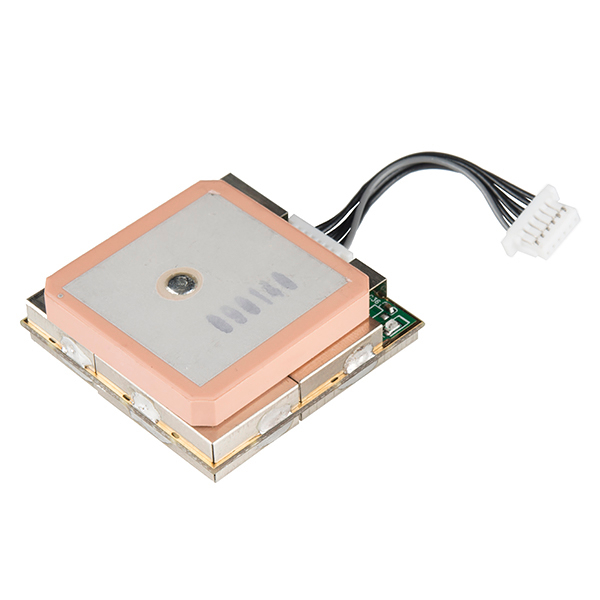
I’ve left Sebi to explore it for couple days, but at some stage he got stacked and couldn’t move forward. It looked like that device is not sending any signals. Well when you get seriously lost it’s a time to RTFM!

On a picture below you can see in a left bottom corner the GPIO and serial JST connectors table. The one we are after is UART (Universal asynchronous receiver-transmitter) labelled as UART (GPS).

However connecting our GPS module to that connector did nothing – like completely nothing. Our BBB didn’t register anything, the LED on that EM-506 practically dead.
Another source of information than was EM-506 Datasheet which sort of indicates that it is a potentially power-hungry beast needing 45-55mA at 4.5-6.5V. And that gave me a clue to connect an external power – and voila – RED LED finally turned ON!
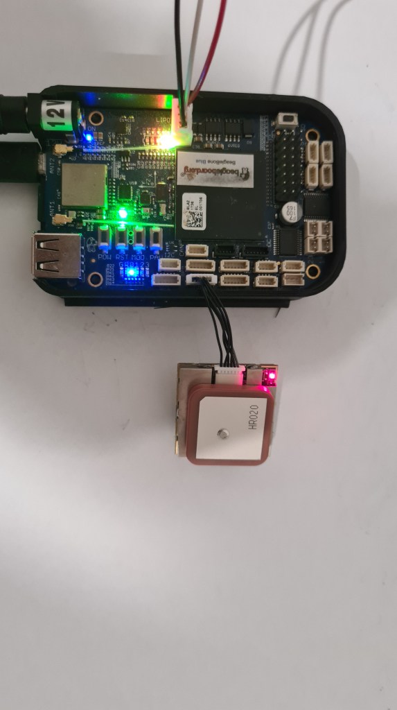
Well, Red LED is on .. but what it actually means? Documentation is quite sparse here, not mentioning anything about its colour.
LED indicator for GPS fix or not fix
LED OFF: Receiver switch off
LED ON: No fixed, Signal searching
LED Flashing: Position Fixed
So let’s assume it is powered on. Now how do we read any data out of it? It took a quite a bit of Googling and finally I was able to cross-reference some clues from different projects which indicated to use the tio – a simple TTY terminal I/O application to easily connect to TTY devices for basic input/output. However there are plenty of those on our BBB.

Reading more through the BBB UG, I sort of ruled out that those /dev/ttyOx are those we need to check and started poking them one by one and at some stage one of them (/dev/ttyO2) started printing some garbage on the screen!

Sebi quickly suggested that this is a wrong baud rate and while documentation was again bit too flexible about which baud should we use (Baud rate based on flash memory setting), we applied trial & error approach again and got a text data out on 4800 bauds!
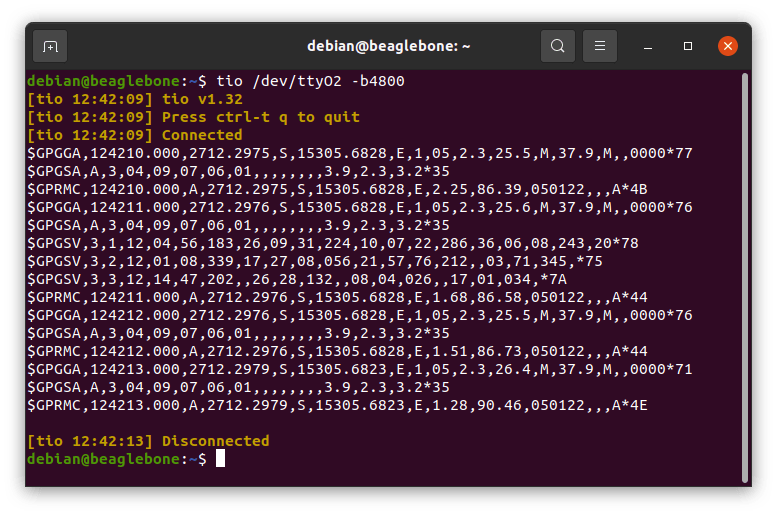
Also our mysterious RED LED started flashing! So what are we looking at?
$GPGGA,124210.000,2712.2975,S,15305.6828,E,1,05,2.3,25.5,M,37.9,M,,000077
This is GPGGA – Global Positioning System Fixed Data Output command
UTC Time 124210.000 hhmmss.sss
Latitude 2712.2975
Southern Hemisphere
Longitude 15305.6828
East
Postion Fix Indicator 1 (GPS SPS Mode, fix valid)
Satellites Used 05
Horizontal Dilution of Precision 2.3
MSL Altitude – +25.5 meters
Geoid Separation +37.9 meters
Diff. Ref. Station ID 0000
Checksum *77
Translated to the GoogleMaps it takes us across the water to Beachmere, Queensland, Australia. Why there (Beachmere is about 10km away) and not to our house? No idea yet, but that’s clearly for another day. 🙂

,
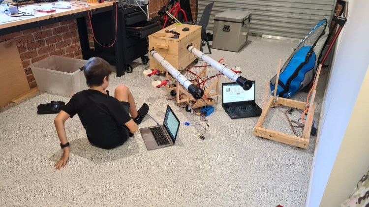
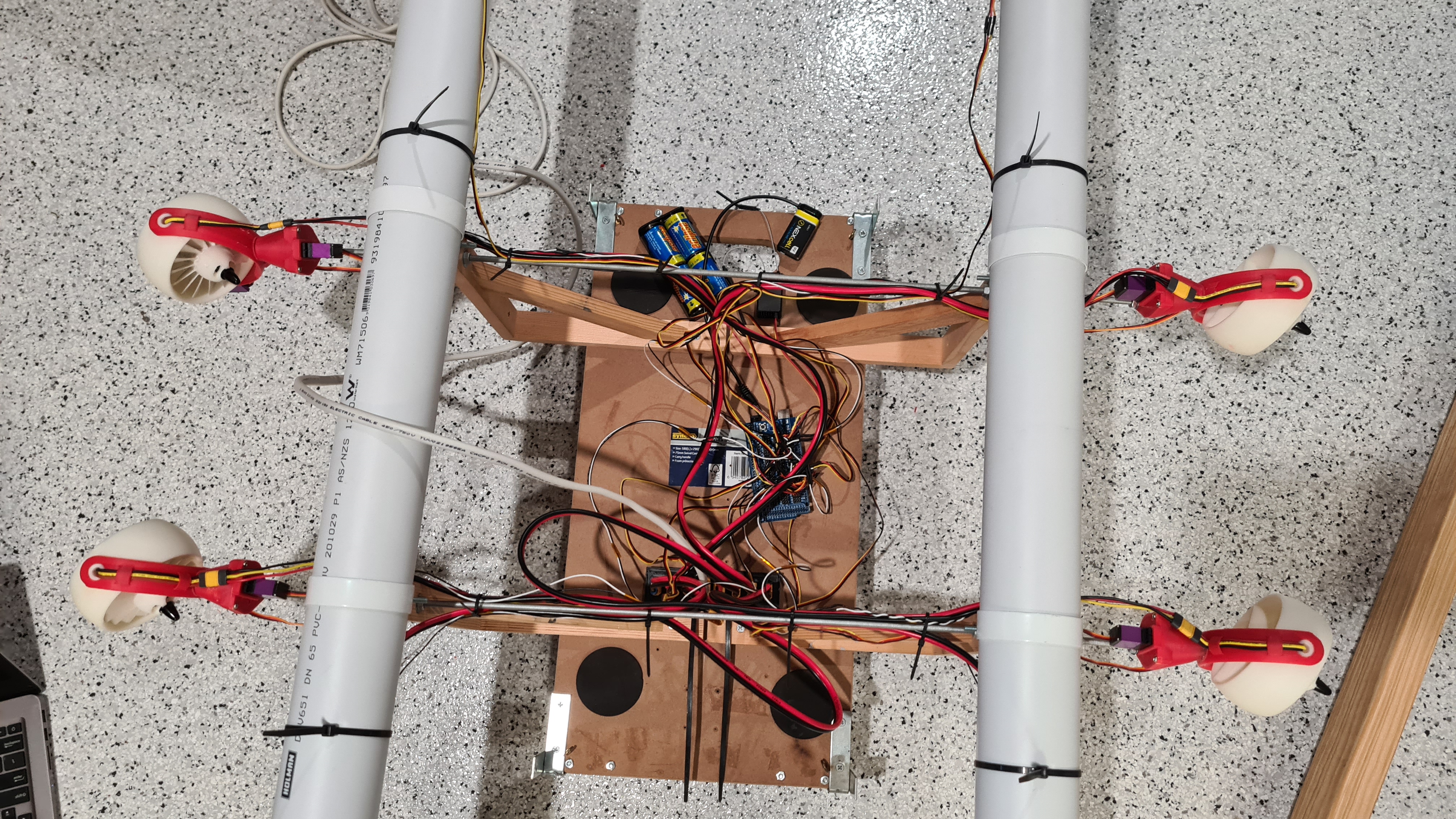
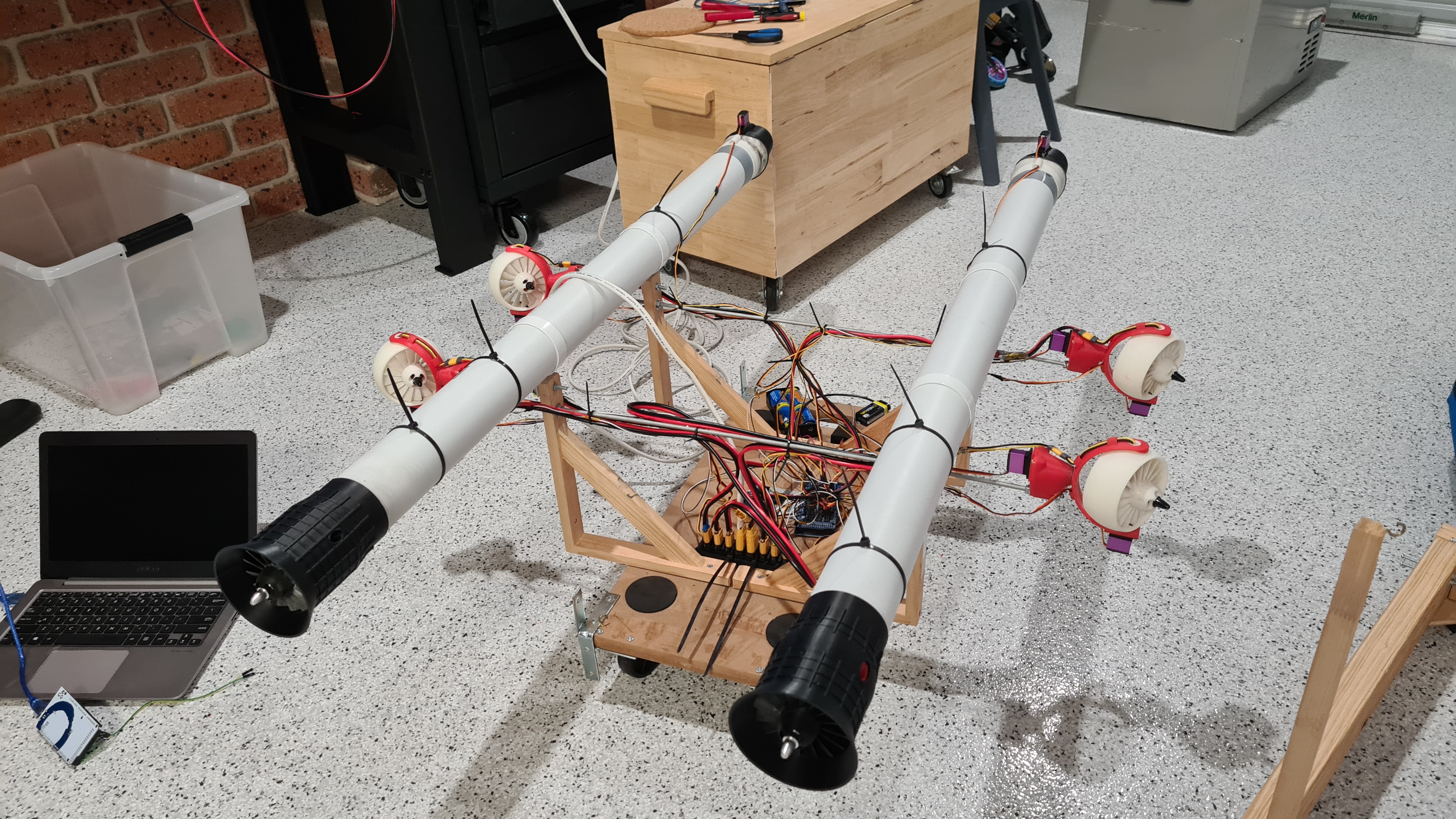
So we have our Gimbals upgrades mounted, added some minor clamps for batteries so they don’t go crazy anymore and battery is fully charged again.
On top of those hardware changes, I’ve recalled that Sebi had some significant difficulties with steering – mainly to keep our card straight on a narrow pavement with and even without a cross wind. We had a discussion on this and Sebi’s been able to demonstrate our problem with a balancing pencil on tip of his finger – or holding it hanging for its tip.
Well, this all made me thinking and I’ve got consequently dragged into some serious reading. Long story short, there are two main competing aircraft configuration concepts – Pusher configuration and Tractor configuration, while with our project we are hitting both with the third one – Push-pull configuration.

Aside of this I thought that providing bit of that “pull” configuration to move center of balance back might be beneficial so I instructed Sebi to code one of his 3-opts switches on his remote to behave like this:
1/ Only front gimbals are operational, rear ones are in their default position – to be used as a default for going forward or for sharp turns.
2/ All gimbals are operational – to be used for initial acceleration, strafing sideways and when full power is needed.
3/ Only rear gimbals are operational, front ones are in their default position – to be used when reversing.
It took Sebi no time to have it ready and I took video of him describing what’s going on.
And we’ve been heading for another test! Well not that fast – just when we’ve been about to start we’ve realized that two 4S ESCs (yes, 4S while we are running on 6S – they’ve been mounted as a temporary replacement) burned out so it took another couple hours to solder in new set.
Ok, now! Sebi will try to go around a blue mark on our local roundabout.
That went pretty well, didn’t it? You could see Sebi switching between mode 1 for keeping directing and mode 2 when he needed to accelerate or do a bit of strafing.
When it goes so well, let’s try a speed test!
That was pretty fast and it was still accelerating! In the last second you can see that Sebi used all 4 gimbals in a reverse-regime to do an emergency stop – super-cool! 🙂
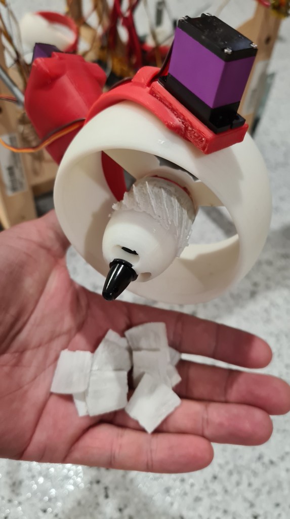
Then we went to the shore to have a bit more fun scaring people and dogs from a pavement and after while I noticed couple of minor defects there. One of the motors got ripped off from its seat again when it lost a screw and propeller lost few blades when hitting the ring. Also another propeller started sliding out from its axle, while quite interestingly still stayed on. But all the rest was holding like nailed.
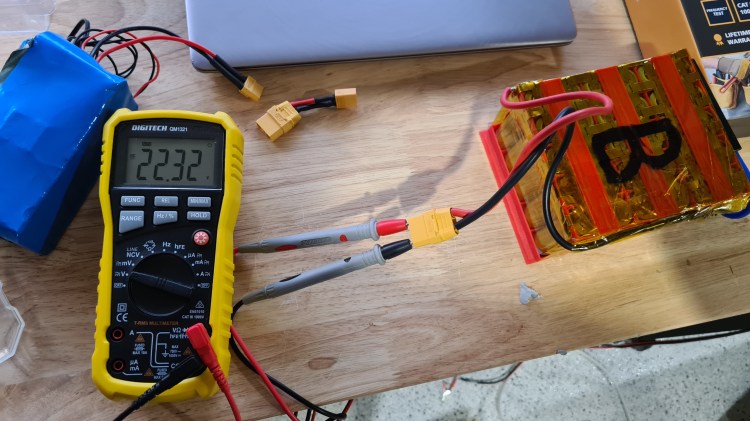
Finally Sebi asked me to check remaining battery power and it came with 22.66V ~> battery being still generously 68% full (min 17.4V, max is 25.1V) and that’s after 30mins + of being very naughty. These battery values are making me pretty happy.

All done for today, I can see we are making some good progress here again! Hope you are liking it too and as always let us know anything what comes to your mind. 🙂
It’s been a while since we did some decent 3D printer upgrade – Last time Sebi introduced RaspberryPi to make our printing much more comfortable and now the time came when he pushed it to another level – a BONELK USB 1080P CLIP ON WEBCAM!

It came in a nice packaging.

And we had is set up in a just a few moments. Camera clipped on a printer frame and it’s USB connector straight to the RaspberryPi (see the top right corner).
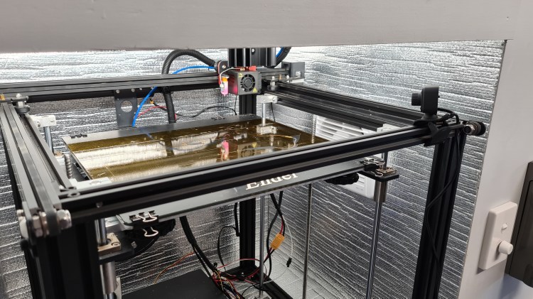
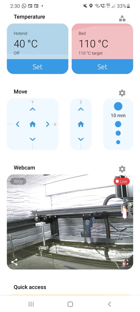
Camera’s been instantly recognised by the Octopi and even without any restart or refresh started providing a live stream from the printer. Picture below is a screen-shot of my mobile running a mobile version of the Octopi when printer is just heating up for another go.
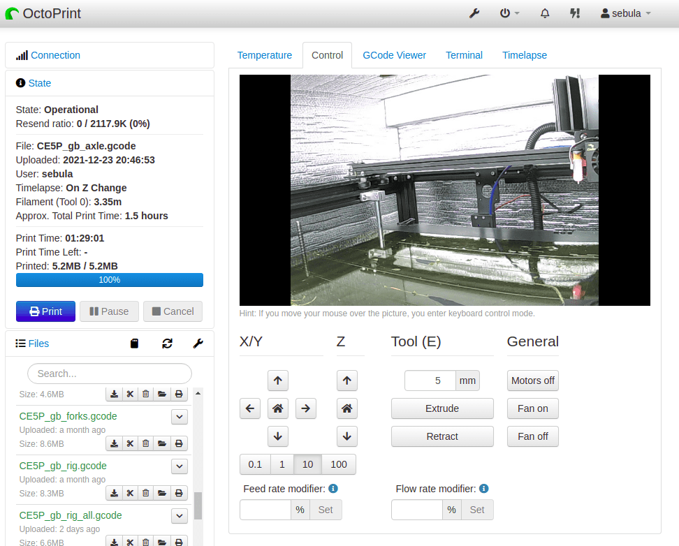
Checking on the actual web interface – many more options came to life there.
Clearly the most tempting one was the Timelapse.
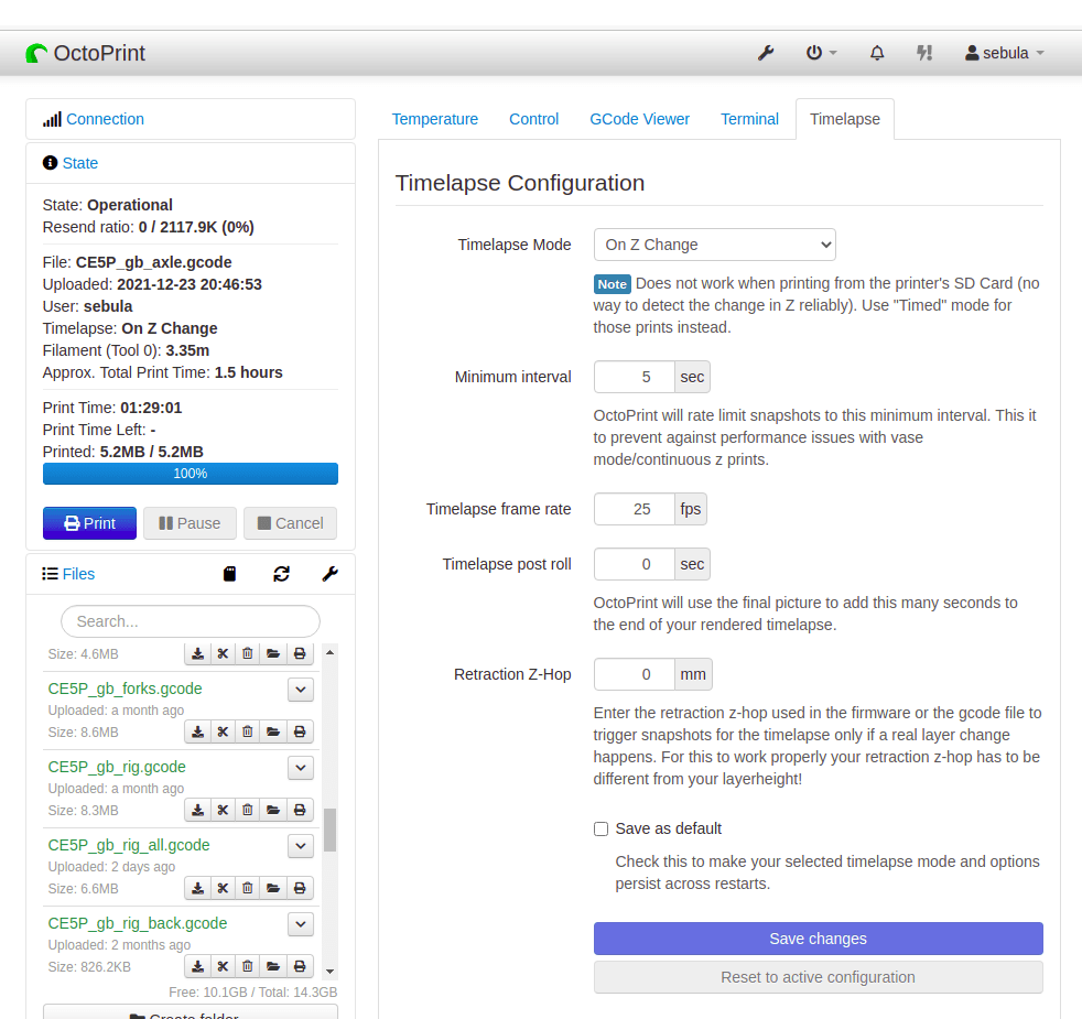
There are three Timelaps Modes – normal, Timed and On Z Change. We’ve tried both interesting ones the normal mode first.
As you can see it comes initially bit blurry and looks like a low quality. However at some stage I realised that there is a manual lenses focus which improved things a lot. Well seeing that one coming well, Sebi suggested to try that “On Z Change” mode – and that was the right one!
As you can see, video is much more entertaining, while clearly capturing all what’s needed. Thank you Sebi, this is awesome, I don’t need to get out of my sofa any more! 🙂

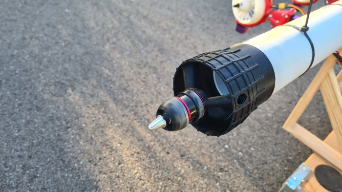
Latest test shown us some weaknesses in the gimbals design. The main one was that the axle was not strong enough to withstand number of forces and moments the controlling mechanism imposed.
For reference this is our “test” axle. You can see that there is not enough material in its narrowest part (at least not for our 3D printed ABS). Also the “head” doesn’t have too much surface to stick to the “fork” properly – so we actually had two event of a clean separation on that joint.
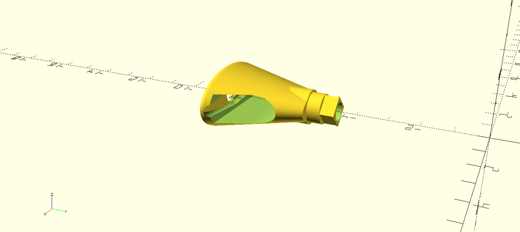
And now this is our new one. I’ve expanded the main part to get more strength (meat) there and added a conical head to get more surface for gluing to the fork. There is also a minor improvement to the lever installation shaft, but just a tiny fix there to fit better.

The gearbox cover also came with a substantial change as my main problem was that it wasn’t properly serviceable. E.g. if the level screw got loose, I would have to re-print the whole thing as the axle was already glued in the fork.


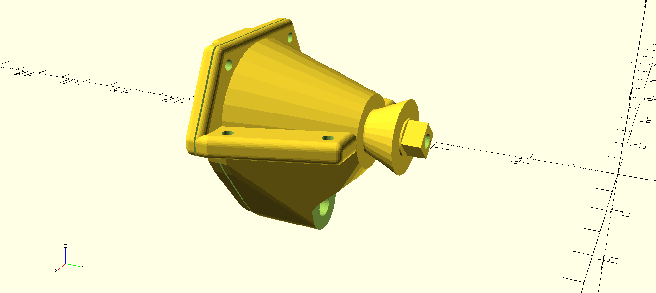
Sebi says it is an overkill, but I split that gearbox in two parts which is now properly bolted together. While it is now not obvious, this also gave me an option to print those parts vertically, which comes with much smoother result.
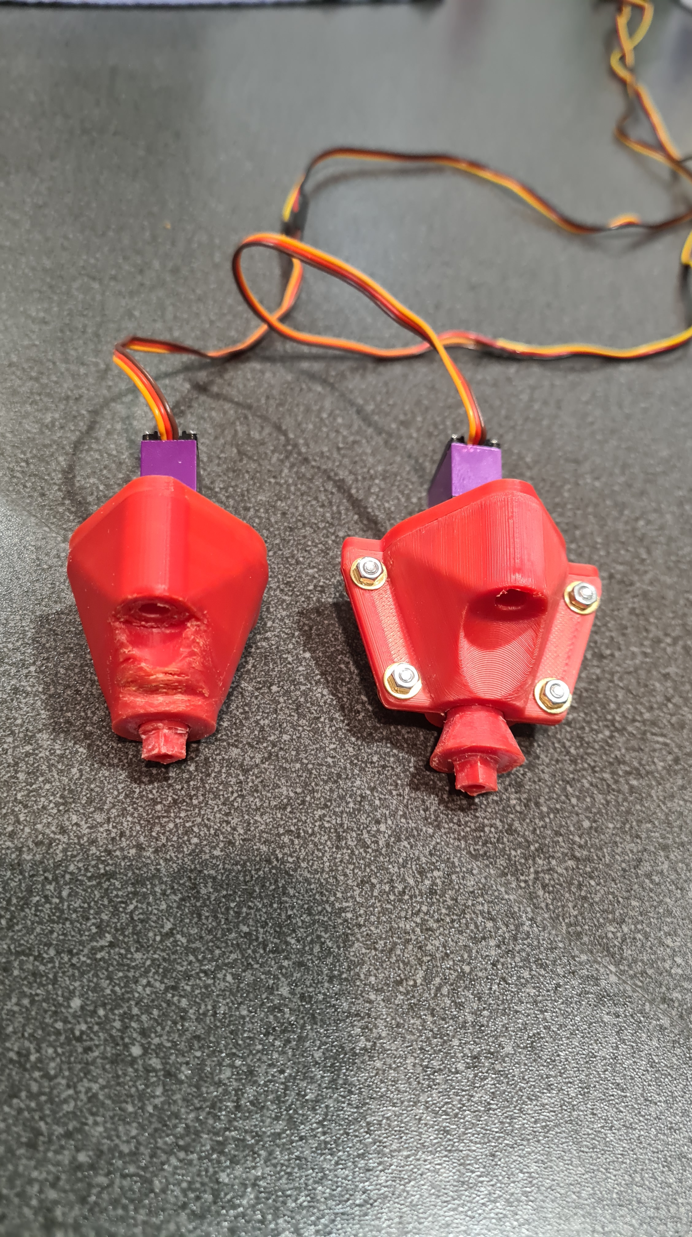
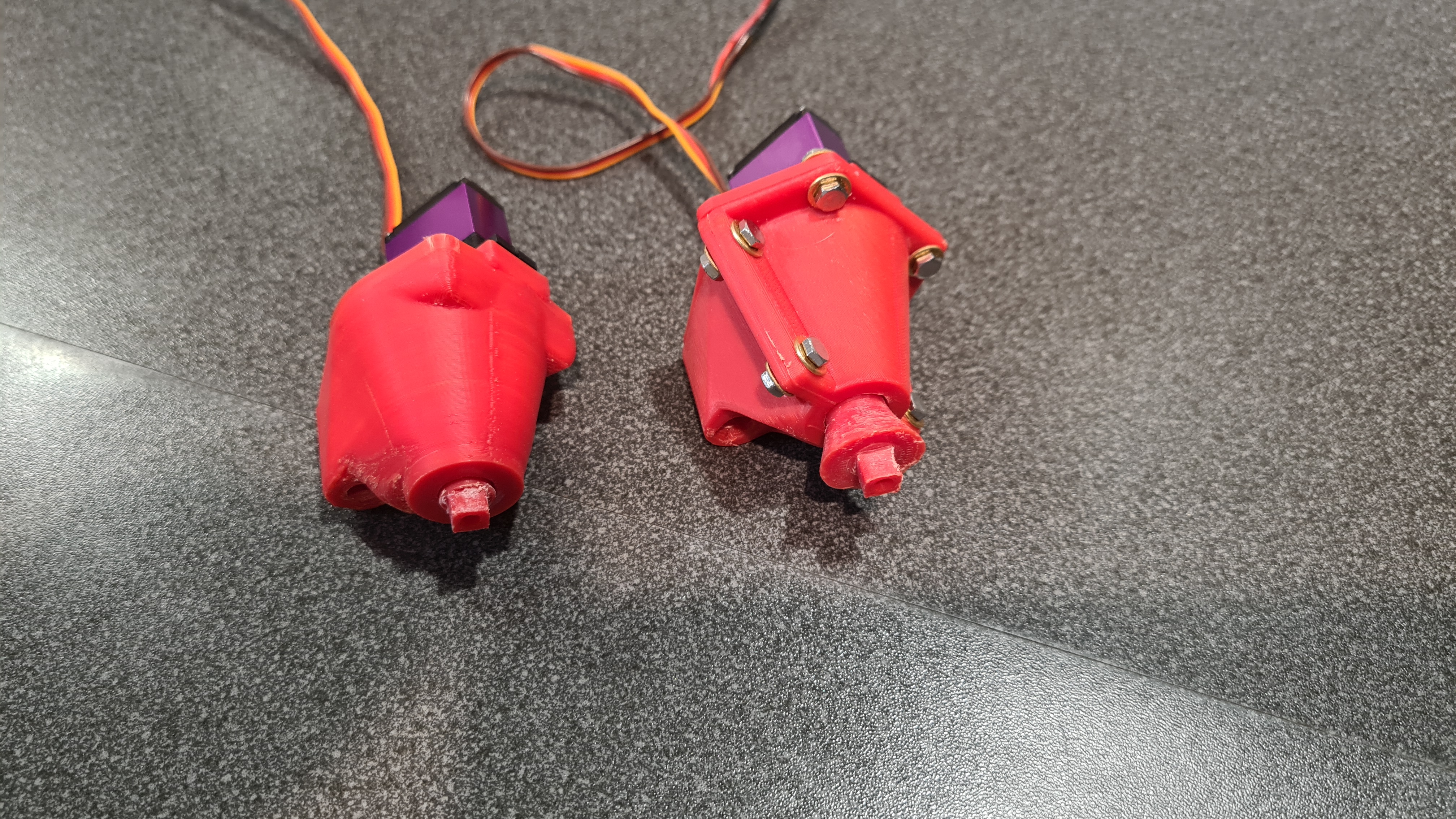
.. and finally – all mounted again. Looks pretty cool, doesn’t it?

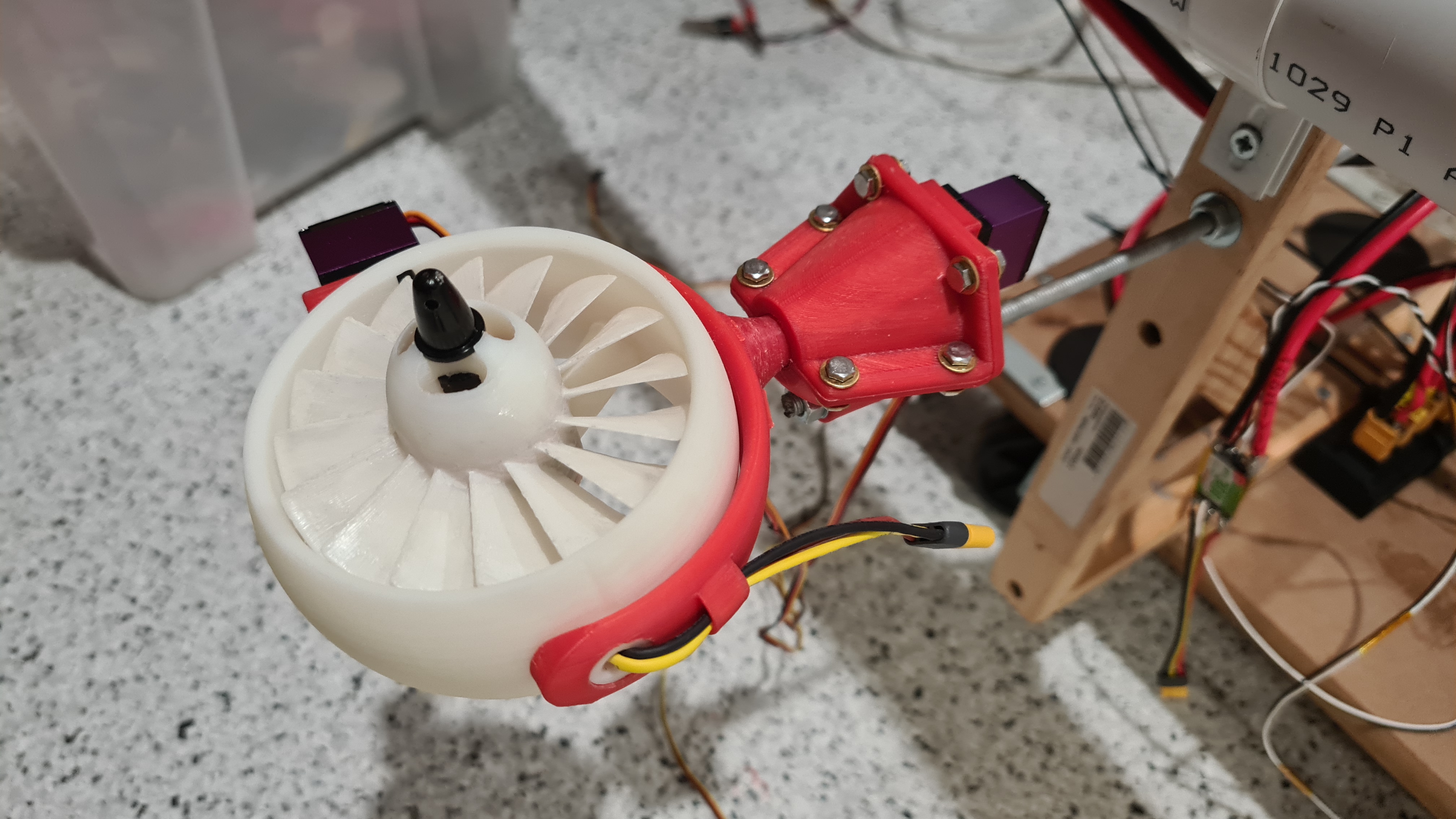
Now three more to go … plus spares!
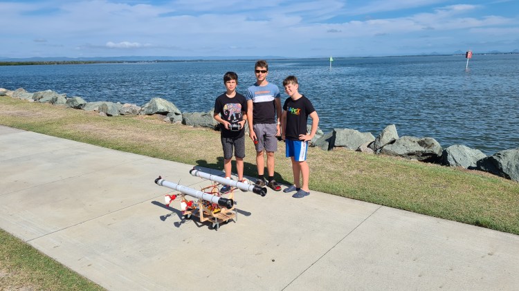
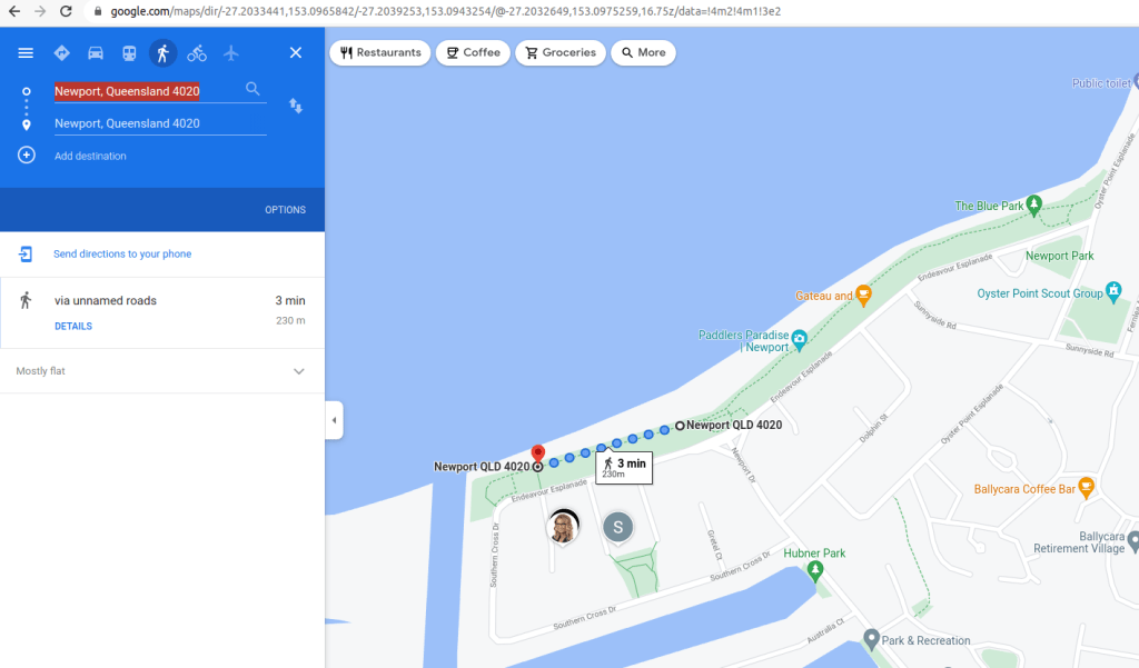
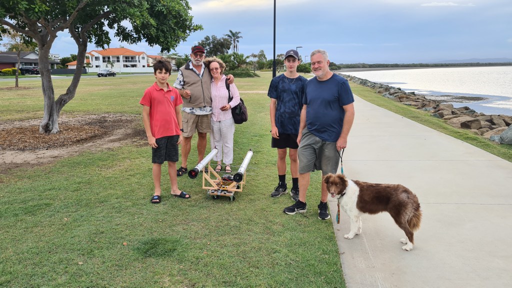
As per our yesterday’s article, all has been prepared and star constellations were favourable so I grabbed boys (Sebi, Jacob and Oli) to the shore to repeat our previous test – get our jet-cart to the Blue park and back (nearly 2km ride).
Map with our trip below.
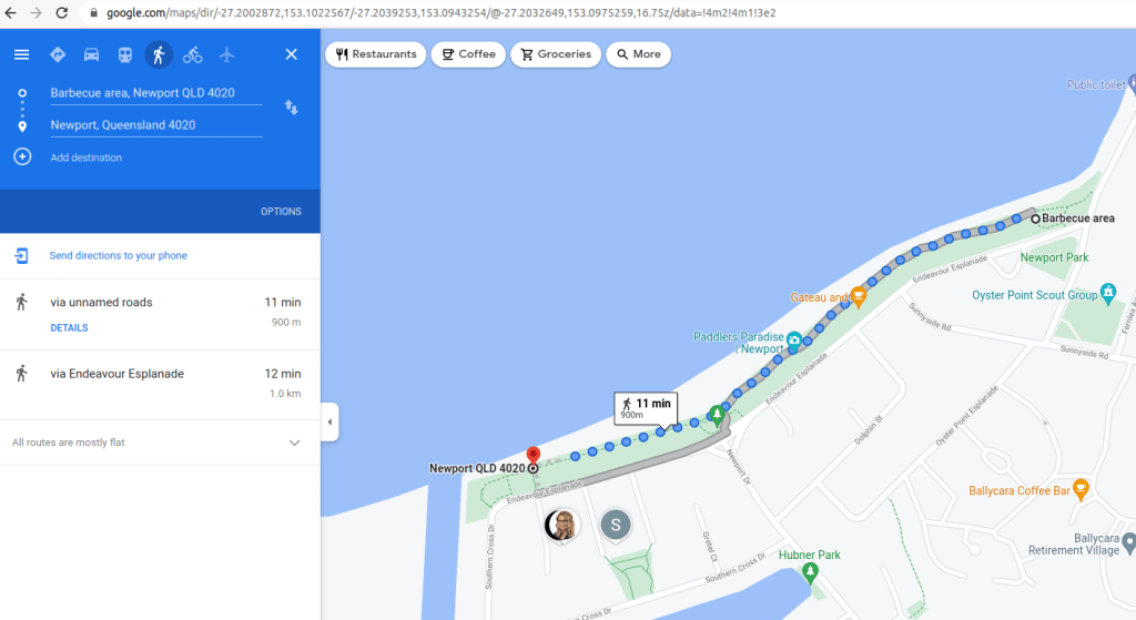
Weather was much better than through our first trial – as you can see we’ve got 11km/h (3 knots) cross-wind to tackle.

I took evidence of our test by taking a picture of Jacob’s watch – it was 8:10 am morning when we started.
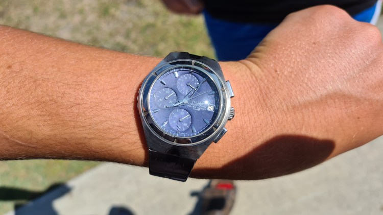
And we have a lift off! 🙂
I took multiple videos of Sebi steering the cart on the pavement, but it’s tilt in combination with that cross wind was giving him a hard time.
And at the end we made it – I took a video when reaching the Blue park!
By that time there were already few defects:


Interestingly, even after loosing 2 gimbals and one vector – Sebi’s been able to keep steering it all the way back! I think it was a coincidence of a cross-wind coming from a starboard and actually absence of those gimbals on the right side, but Sebi did one of the longest stretches there. I think it was more than 200m, while I’ve been able to take a shot of its shorter half.
And that’s it! We’ve discussed the outcome with Sebi and he was much more pleased than with our first test. Clearly the problem was that gimbals’ orientation was unison and he couldn’t use those in some more convenient way. Also covering all that distance and making it back – so satisfying.
Another big win was the battery – real hero of our test. Our battery made it all the way there and back and still remained sort of 60% full (min 17.4V, max is 25.1V).
There were clearly few lessons learned:
Well, just that re-design of gimbals and stocking up on those spares will take us couple weeks. But I am sure it is worth it and while it looks like a chunk of work, it is much easier now when that initial design is already in place. So let’s get back to work!
I hope you had some fun, as always please let me know your comments / ideas, it is always awesome to get some feedback from all of you. Meanwhile, stay tuned! 🙂

We’ve spent practically whole weekend on getting things ready for the main goal of our Phase 3.

And when I say we – we actually had a great help from Jacob, who visited us here in Newport. He did lots of soldering and calibration work on ESCs.

To wrap up Saturday I asked Jacob to give us a bit of overview on what’s working now.
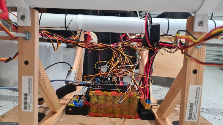
We’ve kept pushing almost whole Sunday where it involved even more cabling, soldering and calibration. Sebi got bit tired, but didn’t give up.
I took few more pictures just to give you a tiny idea how that cabling looks like now, I am getting pretty amazed about all that stuff myself.


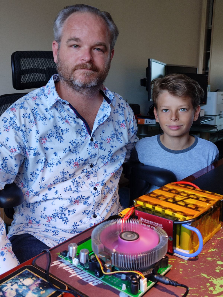
It wouldn’t be that satisfying without giving it a try, agreed? So here is Sebi, demonstrating when it all works together – thursters, vectors, gimbals – all remote controlled, while connected to our 2kW power source. 🙂
I hope you find it so cool as I do and I can’t wait to get it out for a proper ride again.
As you will see, I’ve labeled our battery packs A & B, just to have some easy recognition for those when charging etc. I brought Risa the battery pack B as he agreed to test those battery packs for us. So all his findings below & huge thanks!!


Risa’s comments:
BMS was cutting out at I think ~17.4V
/6 = 2.9V per cell
full charge cut out at 25V
/6 = 4.166V
18.46Ahr / 5 = 3.69Hhr per cell


Risa’s comments:
BMS was cutting out at I think ~17.4V
/6 = 2.9V per cell
full charge cut out at 25V
/6 = 4.166V
17.6Ahr / 5 = 3.52Hhr per cell
| Battery pack A | Battery pack B | Sum | |
| Test length | 27h 1m | 28h 09m | N/A |
| Ah max | 18.46Ah | 17.63Ah | 36.09Ah |
| Wh max | 402.38Wh | 384.23Wh | 786.61Wh |
| Ah per cell | 3.69Ah | 3.52Ah | |
| Weight | 2.487kg | 2.487kg | 4.974kg |
Having both batteries ready we should be now handling quite reasonable 36Ah. Provided that I estimate peak consumption to be 40A, we should be able to go up to 50 minutes full speed with our Jet-cart now! Let’s say that we’ll go 1/2 power average, we can probably go for almost 2 hrs.
I think this is a good start and reasonable promise that we’ll be able to put together enough power (with reasonable power/weight ratio) to make it to another stage!
I’ve asked Risa to provide his summary on all this, so take this paragraph as a placeholder for Risa’s epilogue. 😉
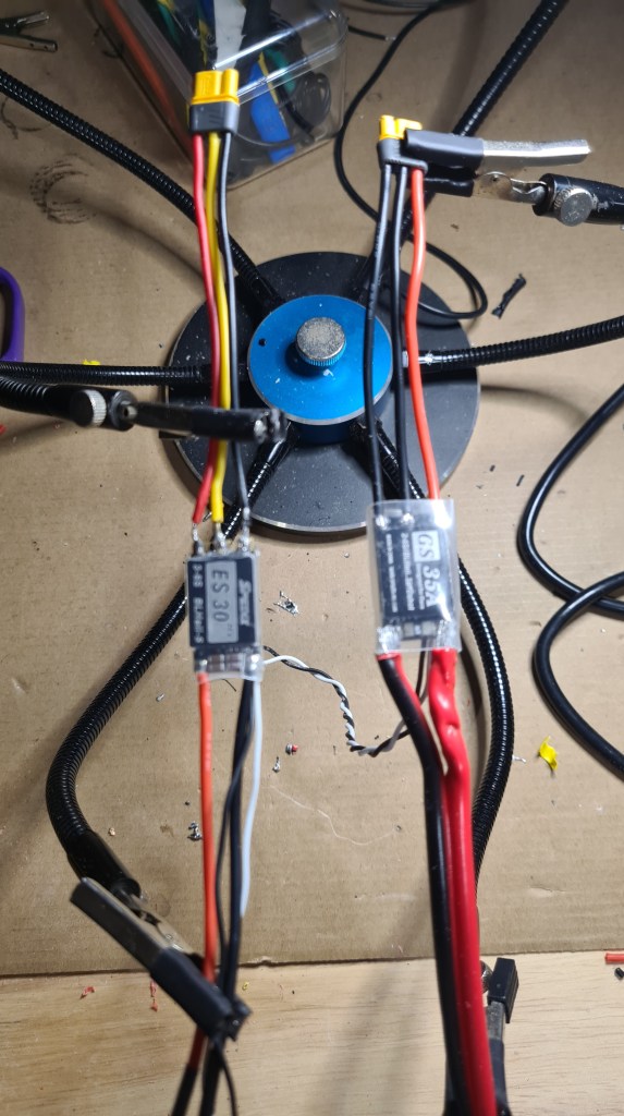
Well, there’s been an accident. Quite a serious one. When we’ve been trying to test some higher powers for our motors – signal cables to our ESCs burned out.

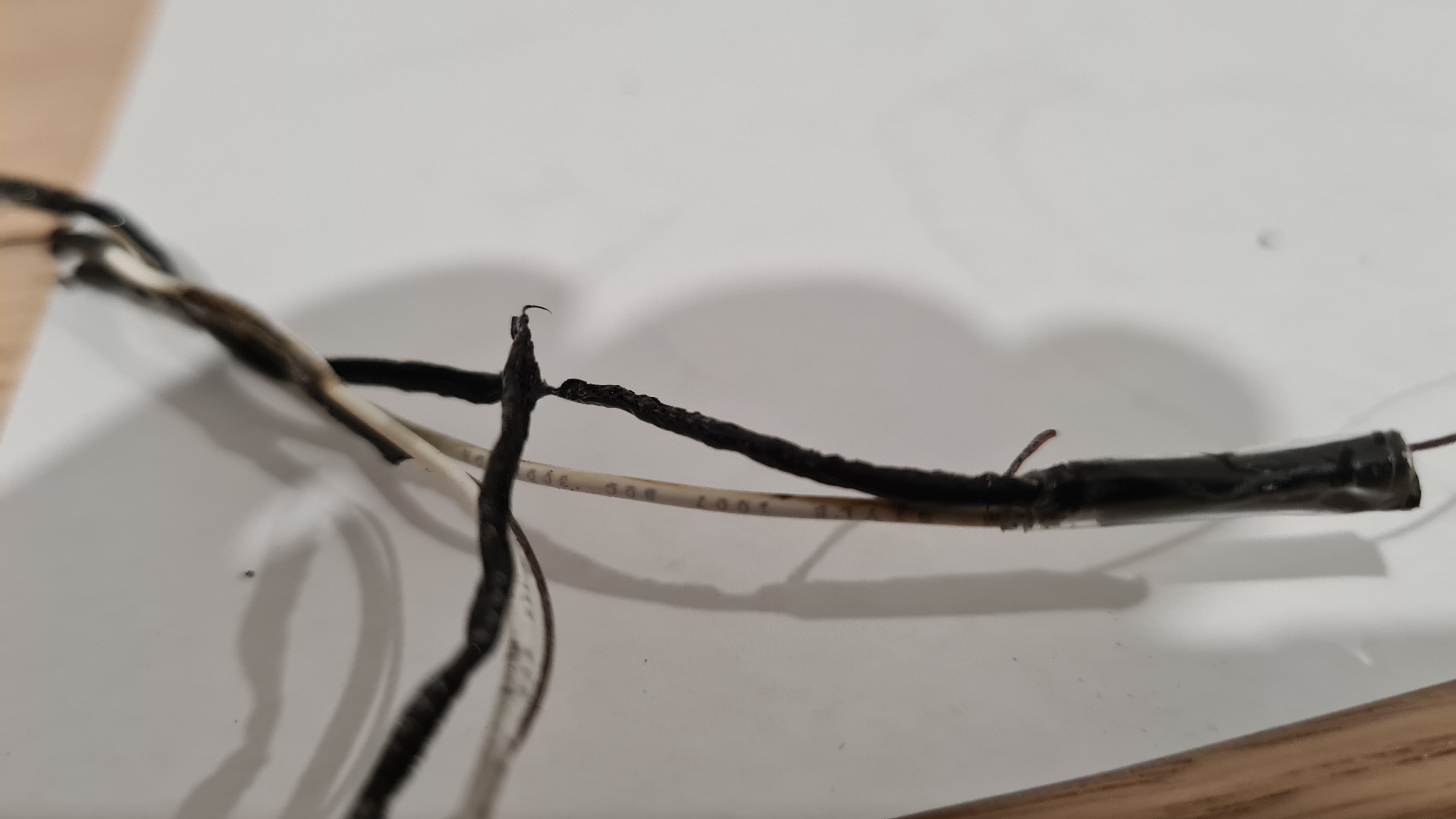
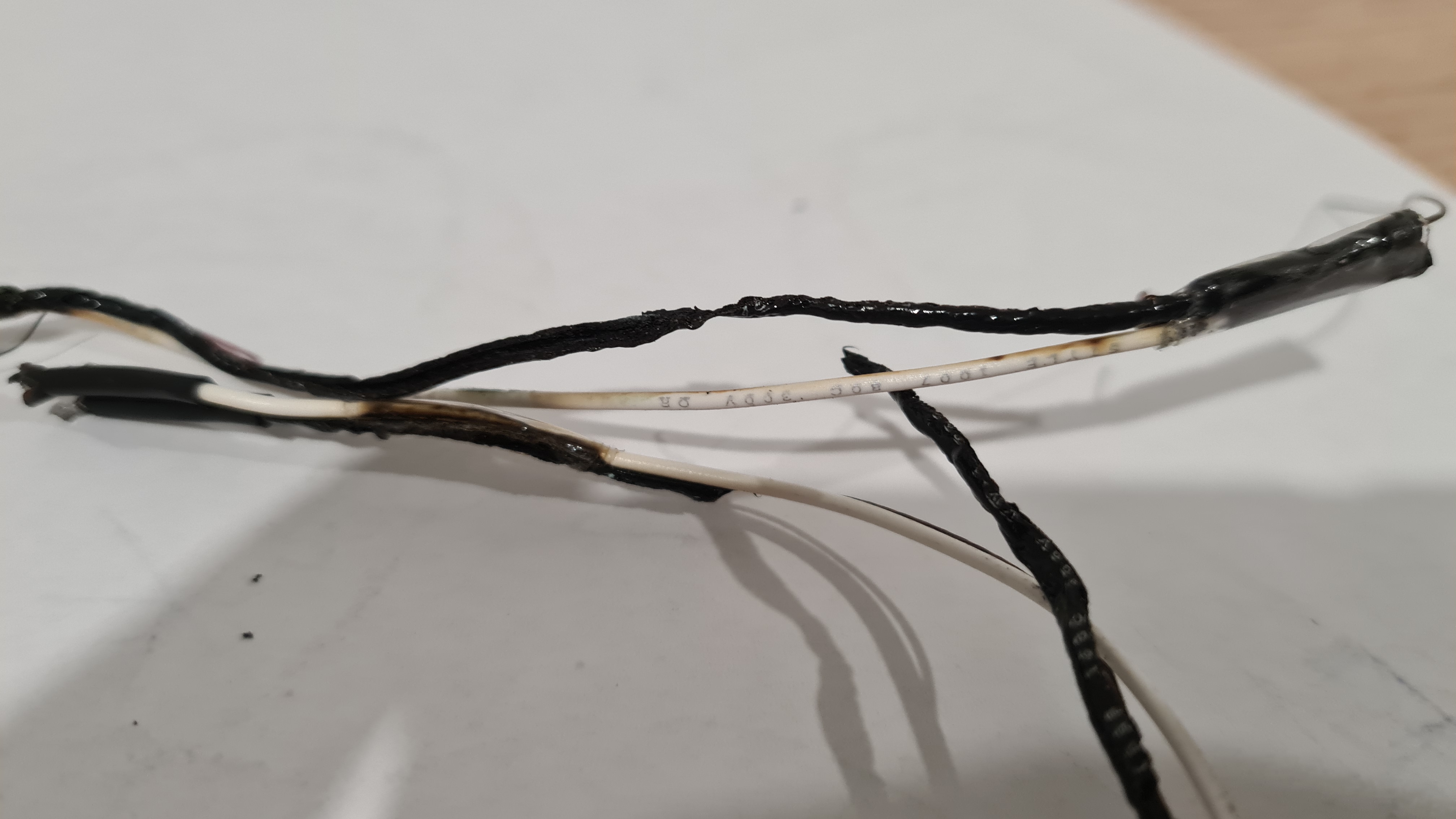
Interestingly, as you can see on pictures above, only the ground cable combusted. The signal cable seem to be ok.
I’ve obviously started thinking where things went wrong and as tried to measure current going trough our power bridge we noticed that part of it burned out / short-cut-ed as well (unfortunately I haven’t taken a picture). Discussing all that story with Risa and Bernard they made me to draw them a diagram first.
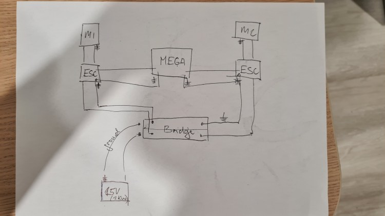
Not sure it it makes any sense, but battery is in a bottom left corner and current is distributed through our Power Bridge to both ESCs, which then control Motors. There are also signal cables going between ESCs and our brain-Arduino.
As wrote above, showing this to Risa and Bernard, I’ve ended up with following update.

There’s been probably lots of current running through a whole system, which was too much for our PCB-based Power Bridge. The big red X shows where our power connector disconnected from PCB and caused a current redirection. Instead of going through the wire “7” it released power through other grounded cables 3->5. And as those were too thin they … combusted.
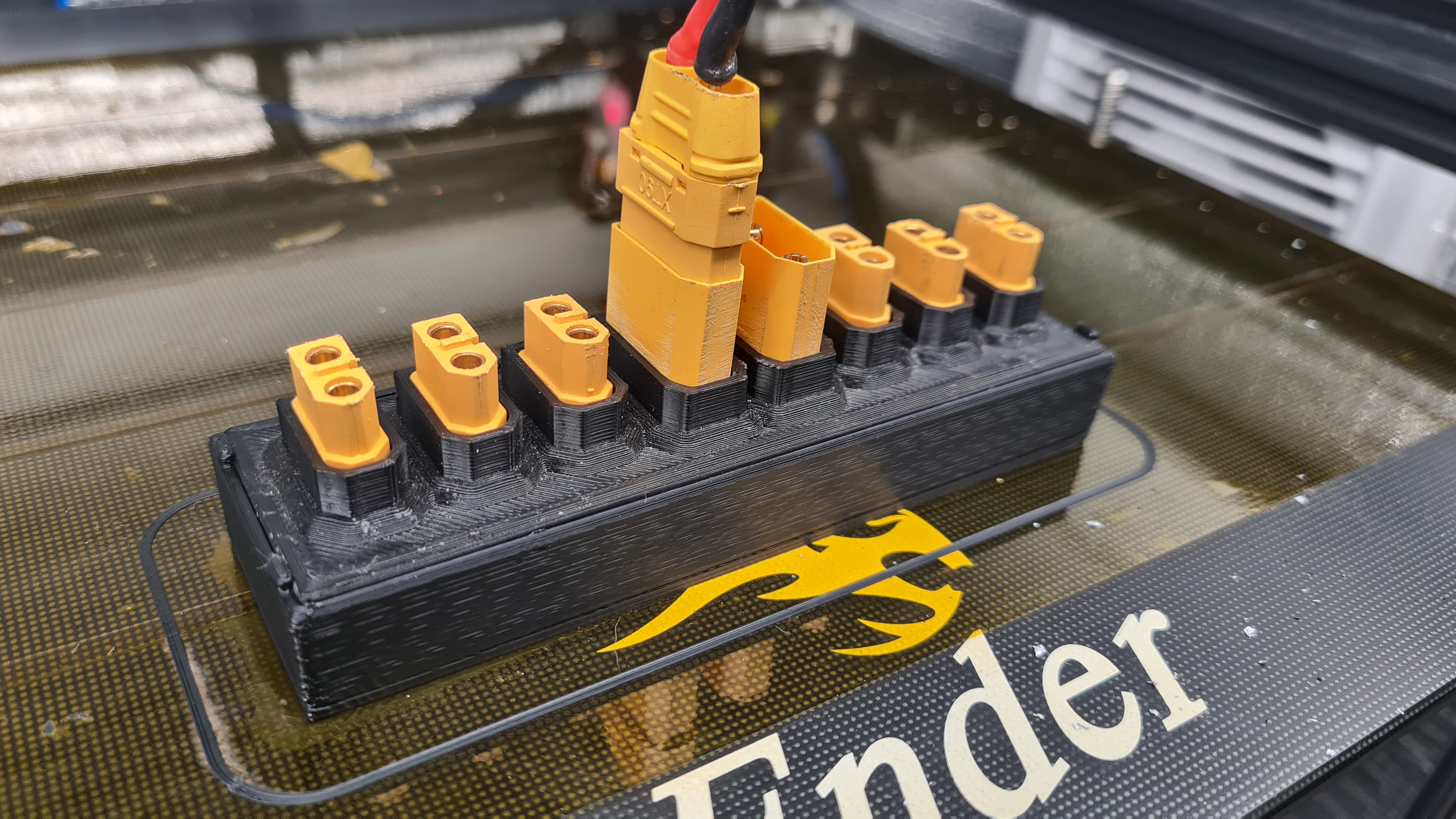
So the first step to tackle this was a complete rewiring of all high-power cables (25A).
Second part of the plan was our power bridge re-design. Sebi cut off all the PCB material and soldered in some serious copper wires.


It all obviously didn’t fit in our old case, so bit of printing was needed as well.
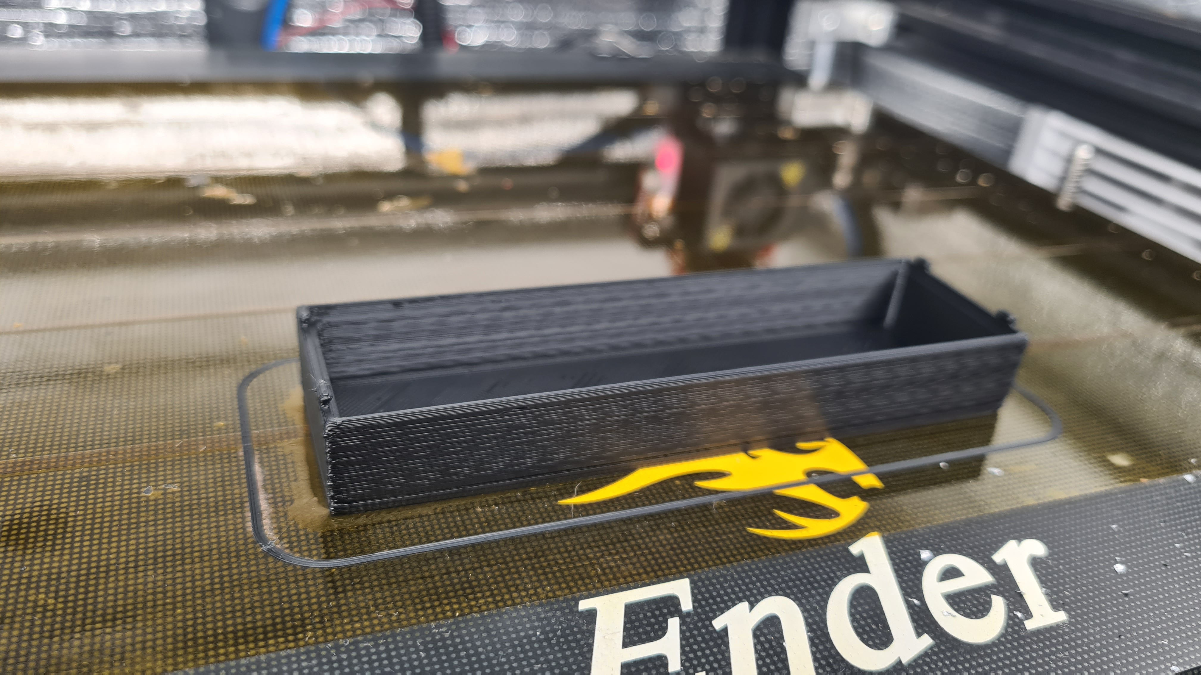
And 3 weeks later we are where we’ve started! 😀 Hopefully it will work out now.
I’ve got some excellent feedback on our latest article Spoilers! from Chris on our internal chat (Discord) where he came with following comment:
I must admit that I closed my eyes when the RPM ramped up at the end, expecting to see a plastic shower! Oh yeah… and do you happen to know the RPM they spin up to?
Chris Drake
… while he instantly followed on that with his typical call for action and got a spectrum analyzer to check that RPM from the video using the Spectral View application. Output out of it surpassed all my expectations, that result looked … colorful.

Luckily Chris immediately provided his commentary – “Most of the test was at 3700hz, ending with a ramp-up to 5200hz (that’s the strongest of all the harmonics anyhow) – not sure if that’s the motor speed, or the rate at which the blades pass by. Multiple those out, and if it’s near 5000 – that’s the motor speed. If it’s wrong by the number-of-blades, then I’ve picked up the wrong thing.”
Chris also noted that common phone Mic’s only can go up to around 20khz, and his phone has a max sample rate of 48khz (making it unable to record anything about 24khz at all), so it’s inconclusive as to what that line maxing out at 5200hz means (it might be a harmonic of something unrecordable).
Of course he also came with some cool suggestions for improvements. For the reference, this is how our propeller looks like today (Chris’ rendering).

.. and now this is a how the most efficient for 2kg (20N) at 20,000 rpm should look like based on his calculations.

While they look quite different, you can see that that “pitch” is not that different. Luckily Chris confirmed that with:
… which is actually pretty close to what you’ve got.
Chris Drake
Thank you Chris! Glad that we are not completely off the scale with this! And I clearly learned something new. 🙂

It’s been bit busy in the office so I haven’t had a moment to finish any of those “in progress” articles, but today we made with Sebi some super cool test of our new gimbal so sharing at least that as a digest of what’s coming 😉
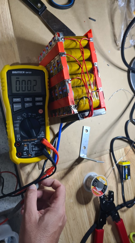
Some lessons are hard to learn. When working on the second battery I’ve got stacked on the step 4 – Make sure that the circuit is No Short.

Measuring the resistance between the BMS cables I should be getting values between 0.0-5 Ω (Ohm), but it was constantly returning something between 8-10Ω.

I even searched for the User Guide for our Multi-meter to check if I am measuring things properly!

Knowing a little about what I am measuring I’ve connected our BMS and it started warming up a bit, but not too much to get me worried. Quick answer to all this was – it is just balancing those cells in series! Well, balancing was a good idea, but when I measured everything again after 24hrs and it was still balancing it started not feeling right. Also the resistance wasn’t dropping, but rather growing. This really ruined my night thinking where I messed up and mainly if I could somehow burn our precious DALY BMS.
I’ve unplugged BMS and started with a cross-check:
So help me to find two differences! Except the obvious – they are same … unless

… checking a voltage on the first one shows 25.2V and the second one -25.2!!!! Well it took us 15 minutes to rewire everything and solder it together again, but all good now – working resistance is down to 0.2Ω.
So after some wrapping we ended up with two (almost identical) super-cool power packs. 🙂
As always, let us know what you think, all comments and ideas are welcome! There has been already a note from Vlada to come up with some case for those to protect them from a mechanical damage – I think it is worth considering! But that’s for another day again.

Sebi couldn’t resist and insisted on testing our latest setup straight on Sunday. Battery fully charged, connectors connected, motors tested, what can go wrong? 🙂

Considering some good testing place I decided that we’ll have no reservations and will be testing straight on a pavement going around our local shore. Sundays here are unfortunately making this spot favourable spots for ahem – Sunday walks, but who would worry about bit of audience. Also to get more support I called out for our local Redcliffe gang to provide us with some cover.
As you can see on a map above – our plan was to cover roughly 1km on a way there and back. However getting to the coast made me bit wonder about the actual weather conditions. So I checked BOM (Australian Bureau Of Meteorology) app on my mobile and took a screenshot.

Can you see that 22km/h wind there – combined with 24km/h gusts? It felt pretty much like that. Well, nothing like a bit of wind could turn us away from our plan. Sebi started warming up motors and also run his stop- watch.

And action!
Yep, one of vectors wasn’t mounted stiffly enough, but nothing what a bit of padding couldn’t fix. We’ve kept going! Luckily Robing kept taking more videos.
And the last one!
The last part is missing – the one when we lost a propeller. Anyway I think we’ve covered nice 100 meters before we had to stop for today.
I think that this is pretty result, taking that this was our first serious go and all those unforgiving weather conditions. Sebi wasn’t too happy, he’s been looking for more, but I think we did pretty well. We’ll make it happen next time! 🙂
Huge thanks for a full gang for support and see you soon on another attempt. 🙂
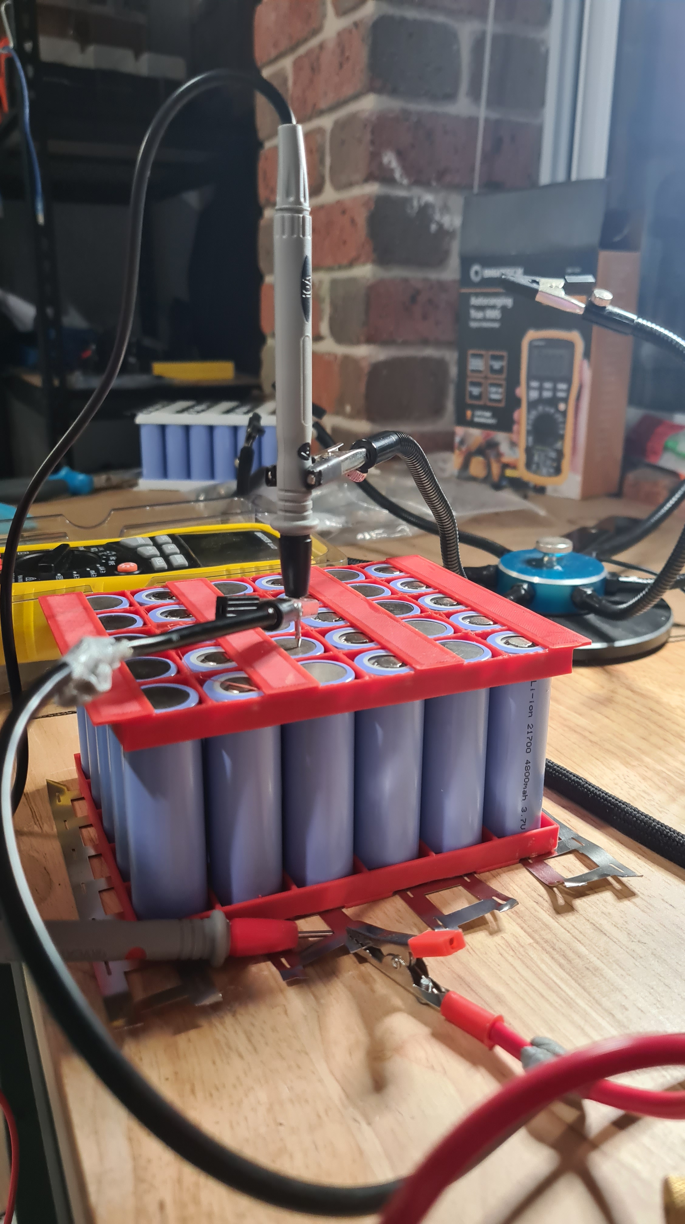
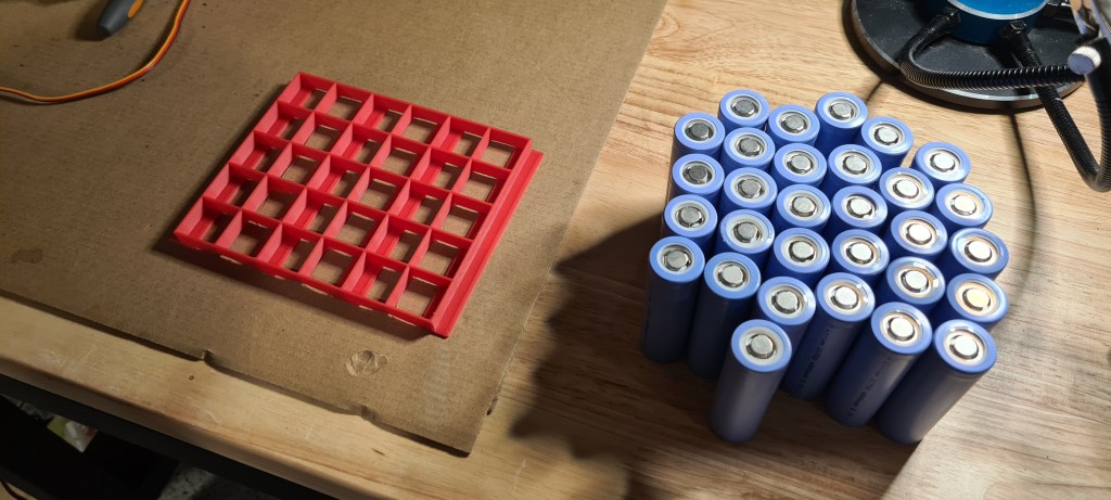
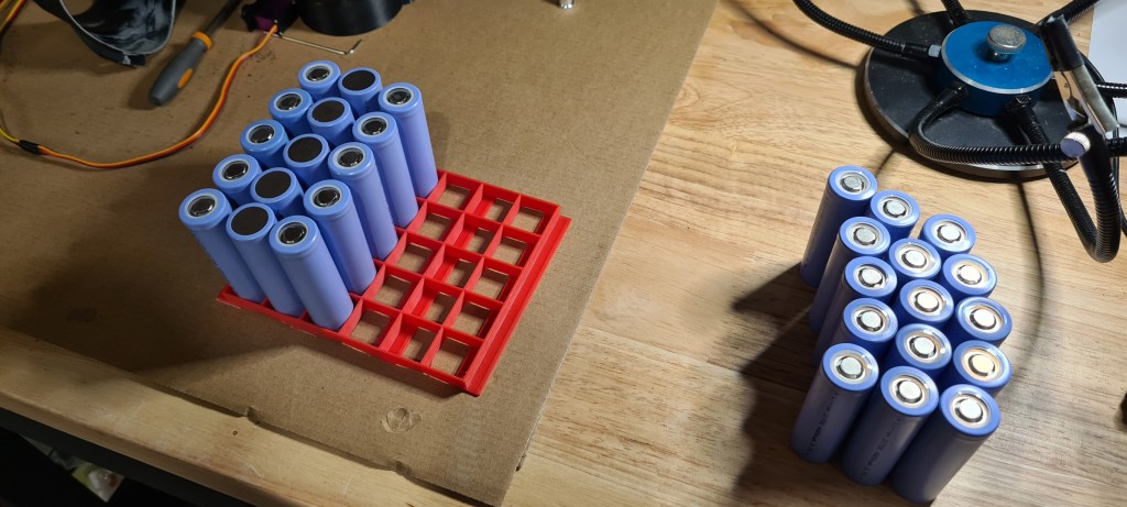
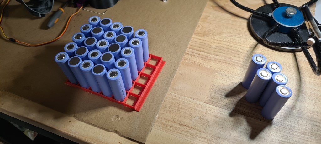
This is a direct continuation of my previous article Make your own Battery pack – spot welding fun, so if you haven’t read it, get there first or you’ll be missing lots of context.
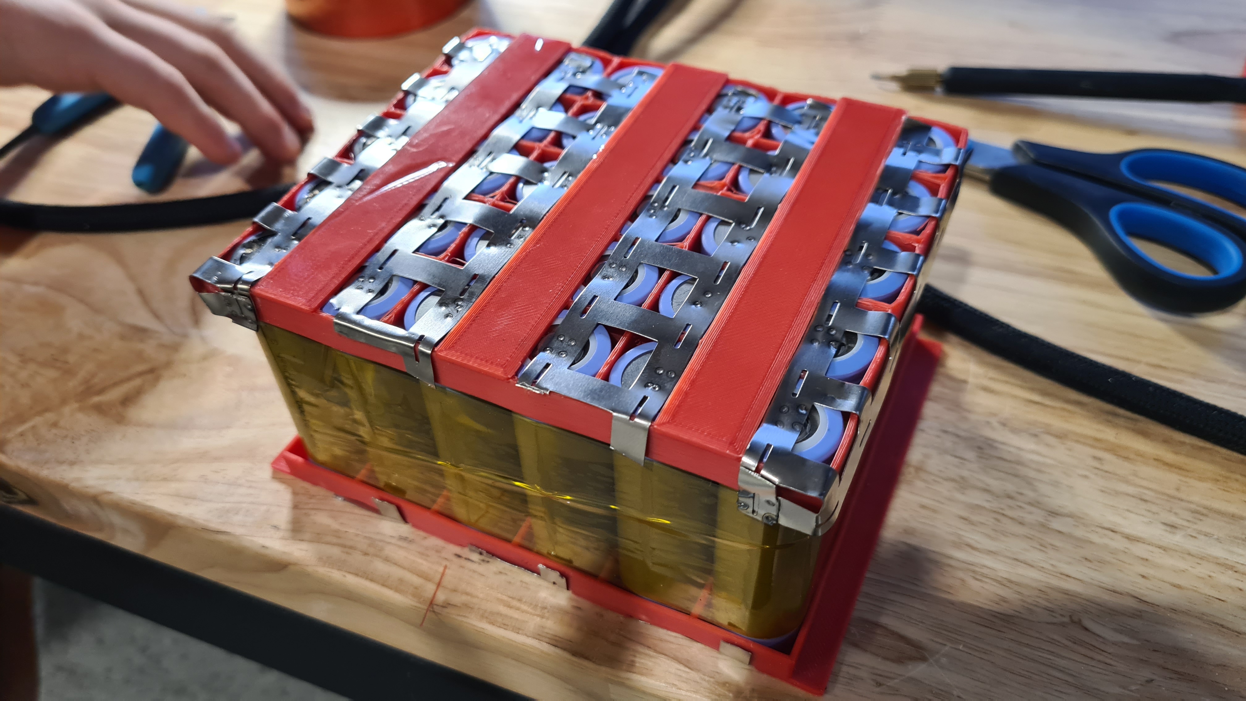
We’ve left of when most of welding was already done and while we instantly jumped on a battery wrapping an wiring I still needed to do a bit of review of all material we’ve been able to collect to progress further.
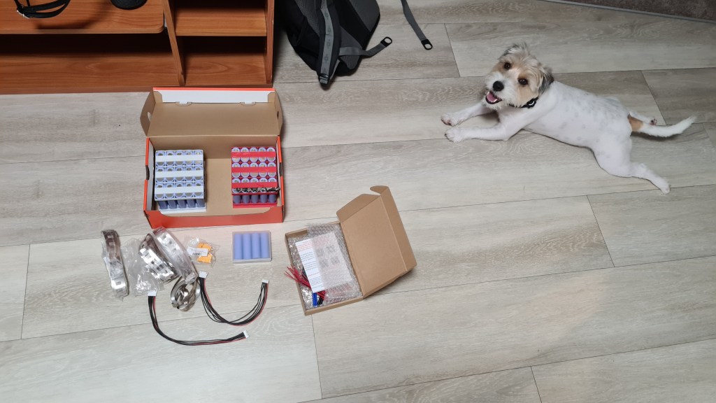
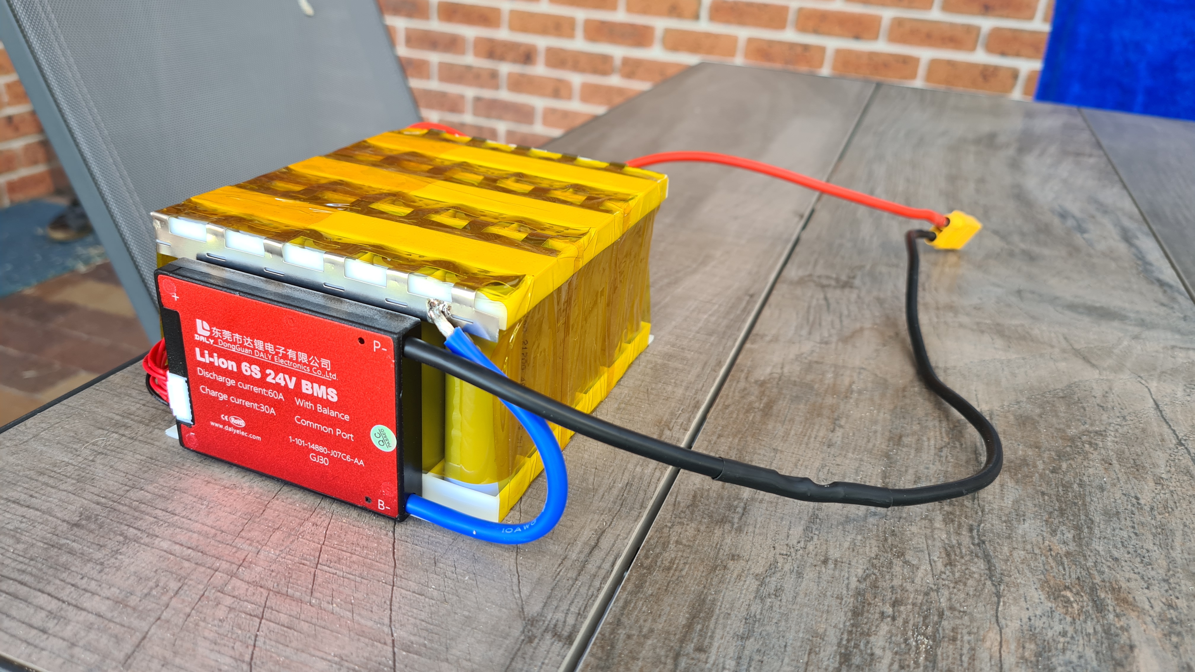
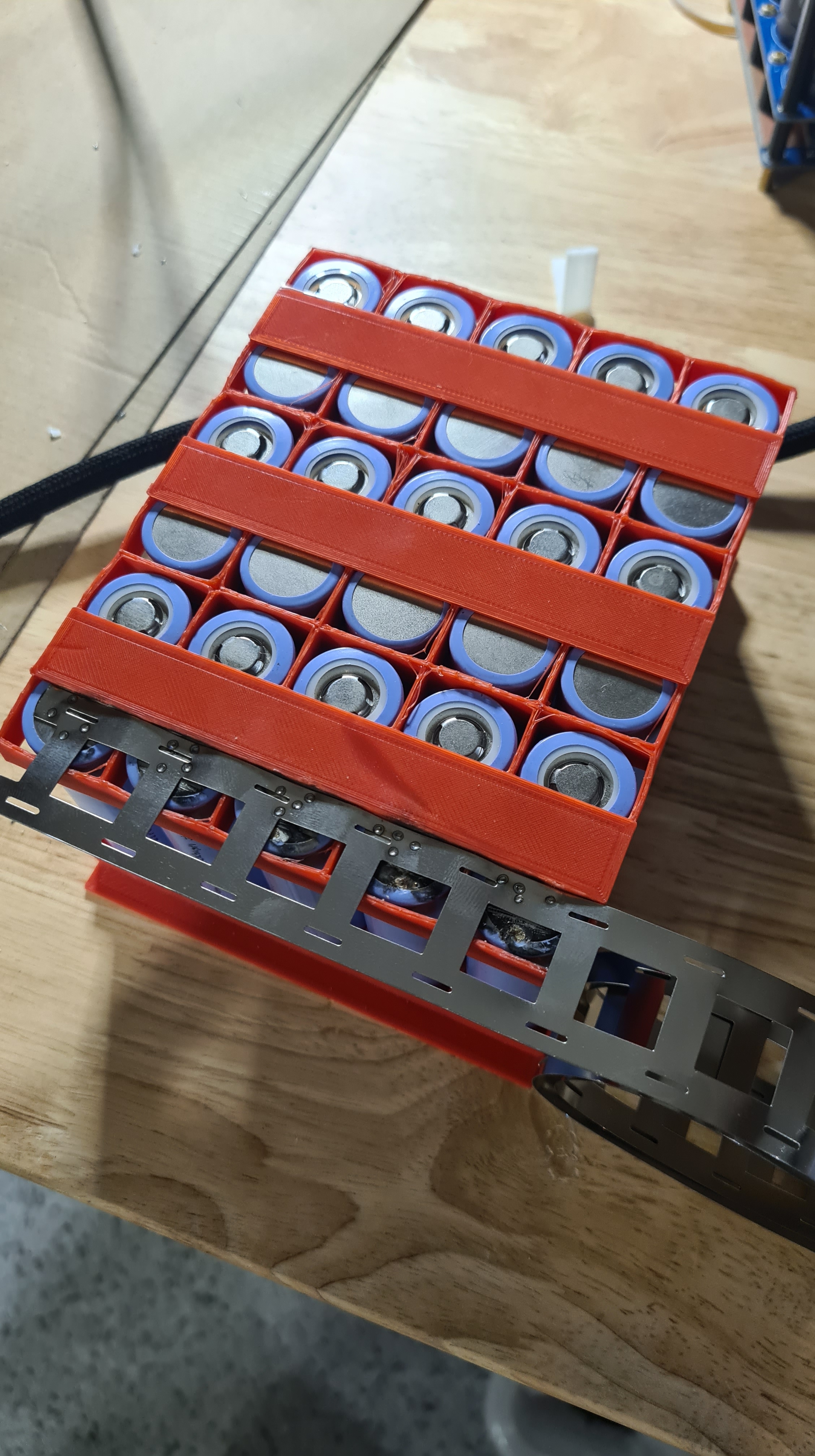
On the picture above you see two main (to be) battery packs in their racks. That makes two-times 6×5 battery cells + 4 spare ones. There are three packs of 2C Nickel strips, two 6S balancing cables and two male XT90 connectors. There is also a box with two 6S 30A DALY BMSs (Battery Management System), which came from China through Fedex and just getting them to my hands would be a story on its own.

BMS above is a clearly a hero of our today’s story. Our current situation is that we have one completely welded battery pack, but it still needs proper wrapping and needs to be connected to the BMS. Let’s start with wrapping. One layer of Kapton did a job to make it more look compact.

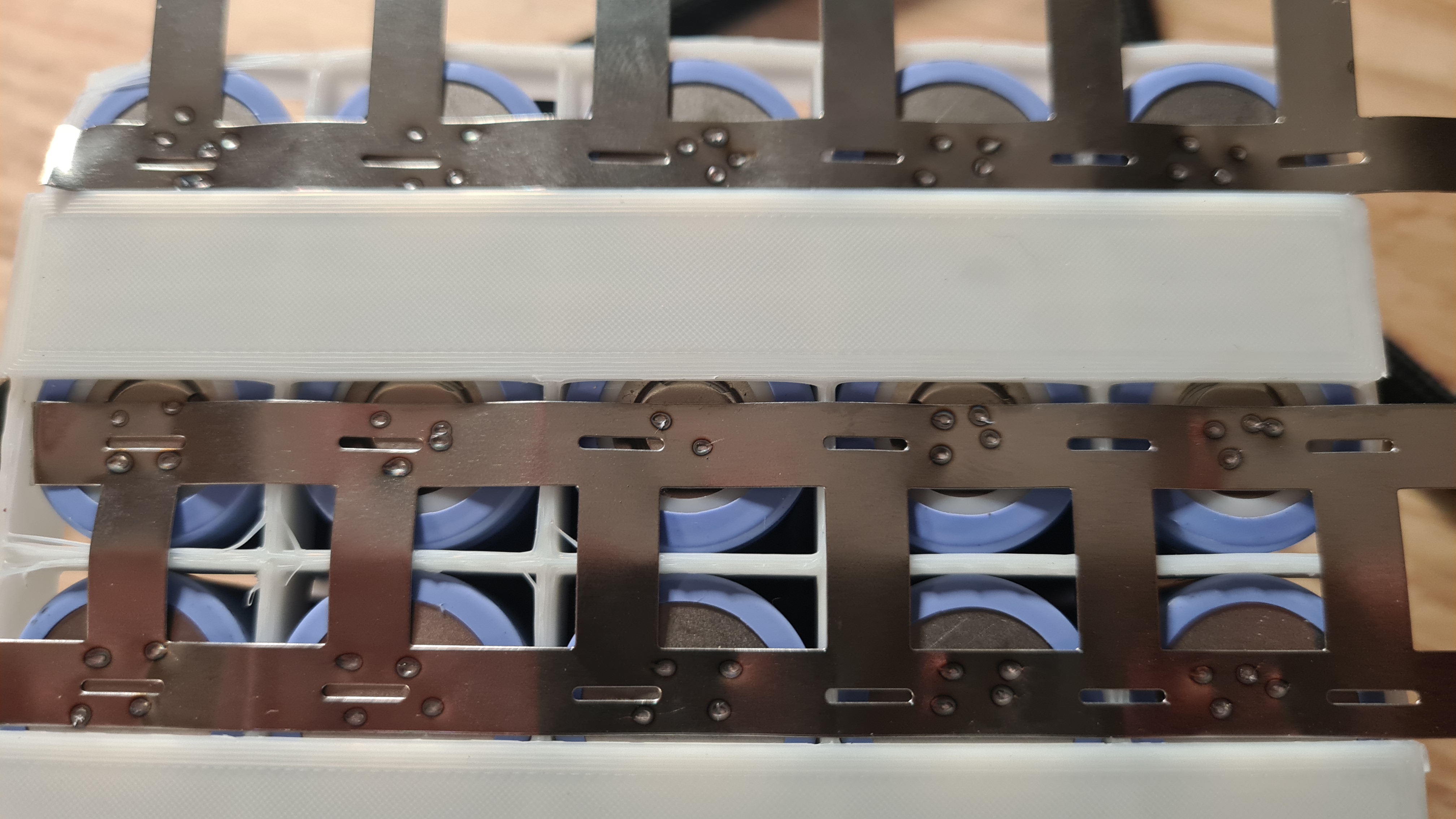
Wiring next. Wiring instructions are bit cryptic, but pictures are sort of self explaining.
So it is simple .. just connect all cells in parallel sets to its relevant cable and don’t mess up! How about this? Actually I’ve learned a lot – mostly that when it is all coming to life you are starting to deal with some interesting currents here. There were couple times more sparks than what I would like and also got buzzed once from that welder.

I have just a little idea what I am measuring here, but Vlada says it is a working-resistance. It needs to be between 0 and 5Ω and it says 0.2. I think we are fine. I used a bit of Velcro to strap that BMS to the battery.

Last bit was more Kapton wrapping. Looks beautiful, doesn’t it?

Being super happy, I also took a video to show off with our master-piece. 😉
Next stage – darn how could you exactly charge this thing? Luckily once you have some reasonable BMS there, things are getting pretty easy – just connect it to some reliable PSU and BMS will take care of rest.
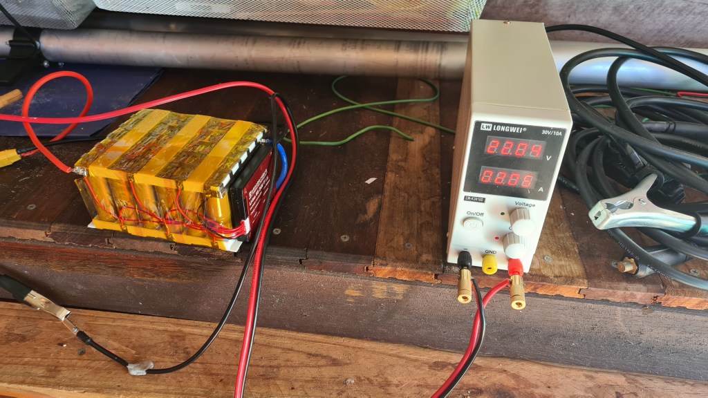
It took couple hours, so Sebi setup a tiny monitoring set.
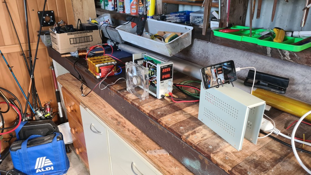
And here is our IT guru monitoring the charging itself from the comfort of our kitchen.

I don’t have a picture showing how that battery pack looks all charged, but our multi-meter was reporting some 25.2V. Still took a last shot, putting our final product on scales to check how we are doing weight-wise – reading pretty much 2.5kg on the dot.

This was one seriously productive weekend, can’t wait to see how it performs!
Couple weeks ago we’ve ended up last time with having a battery rack ready. Honestly not everything went that good as I was hoping for since, so we’ve hit about a week-ish delay on my plan. It looks like spot-welding is pretty difficult without a proper spot welder! Luckily Richard came back with an idea that he has some DIY one which should do the job. Here it is!
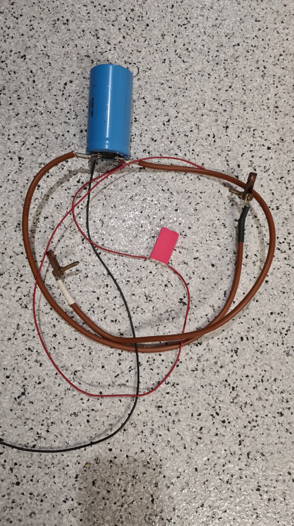
As you can see, it is just a simple-huge capacitor with a resistor to shield it from crashing a power source. Risa invited me to demonstrate how it is working and while it was giving super-cool sparks results didn’t make me confident that this is a way to go.

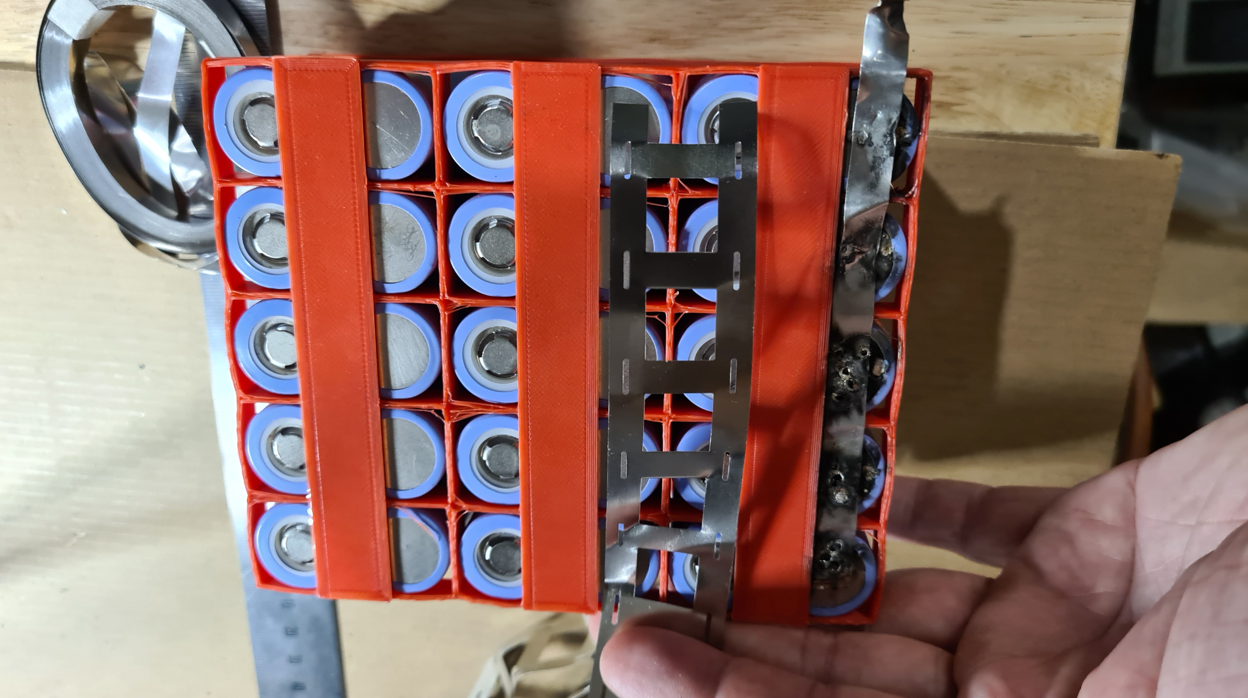
As you see on the last picture – nickel was quite damaged and it didn’t look reliable at all. Anyway we had couple beers and quite a fun trying and I took a video of Risa doing his best – Thank you Riso! 🙂
Needed to move on with the project, I started asking all around if someone would be able to borrow me a spot welder for a day or two – and Chris Drake came back! Luckily he had a trip around practically a next day when having some errands in Brisbane and brought me his own. And here it is – including a bag of Nickel. Thank you Chris!!!

While it looks quite wild and carries practically no label, it feels very very solid. I tried to locate that product on a web to get one on my own and while I can’t be 100% sure I think it is this one. Santa, if you are reading this – this is what I need! 😀
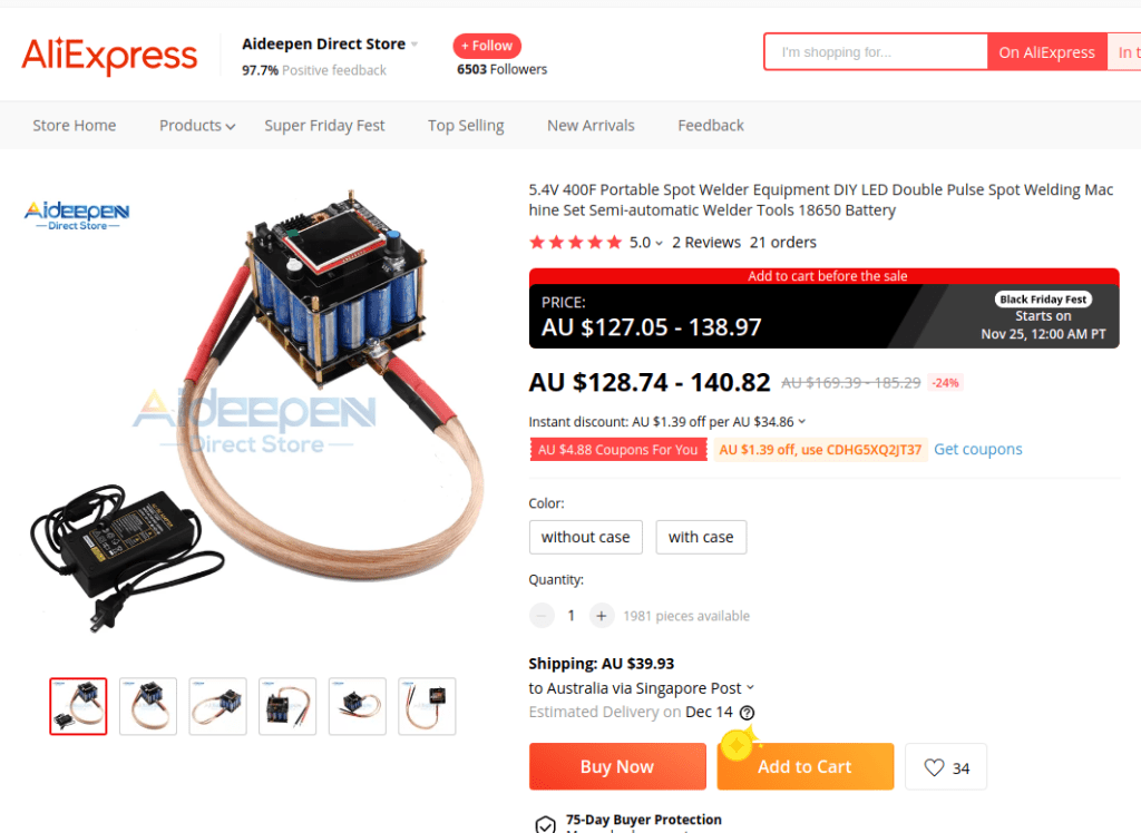
Anyway, it came with instructions – have a Nickel 0.2mm thick, then wait for it to charge first and use it with settings: pulse 1 is 25ms, pulse 2 is 20ms. This seem to be important enough that the owner made a note for himself straight on the case:
Now having access to the spot welder we should have everything for getting it all done! Well, making your own battery is easy, but there are few bits where it things ca go wrong. Perhaps that most important one (Thank you Riso) is to make sure that all cells are balanced on a same voltage, mainly those in parallel connection as they will attempt to re-balance at the moment when they are connected – potentially leading to an instant and spectacular charge/discharge. No need to say that consequences can be … well let’s just do everything to prevent it.
As you can see on the picture below, testing was fun. Majority of all batteries was around 3.6V +- 0.05, which I think is ok.

How ever there were few which needed an additional push. Luckily it wasn’t much a problem with topping them up with our PSU.

Unfortunately couple of those also needed to discharge and as our PSU doesn’t have that feature, Sebi put together a device to take care of that. Man it took so long to discharge one from 4.4V back to 3.6 – almost a day! Sebi needed to add one of our spare hi-LEDs to get us moving.

Meanwhile we’ve progressed on some serious welding. I you are having an impression that pictures are not a in correct timing sequence – all good, we’ve been working on two batteries in parallel and I thought it wouldn’t look too good interlacing story between those two processes.


Anyway, when I’ve got things in my hands, I asked Oli and Sebi to have a go as well.
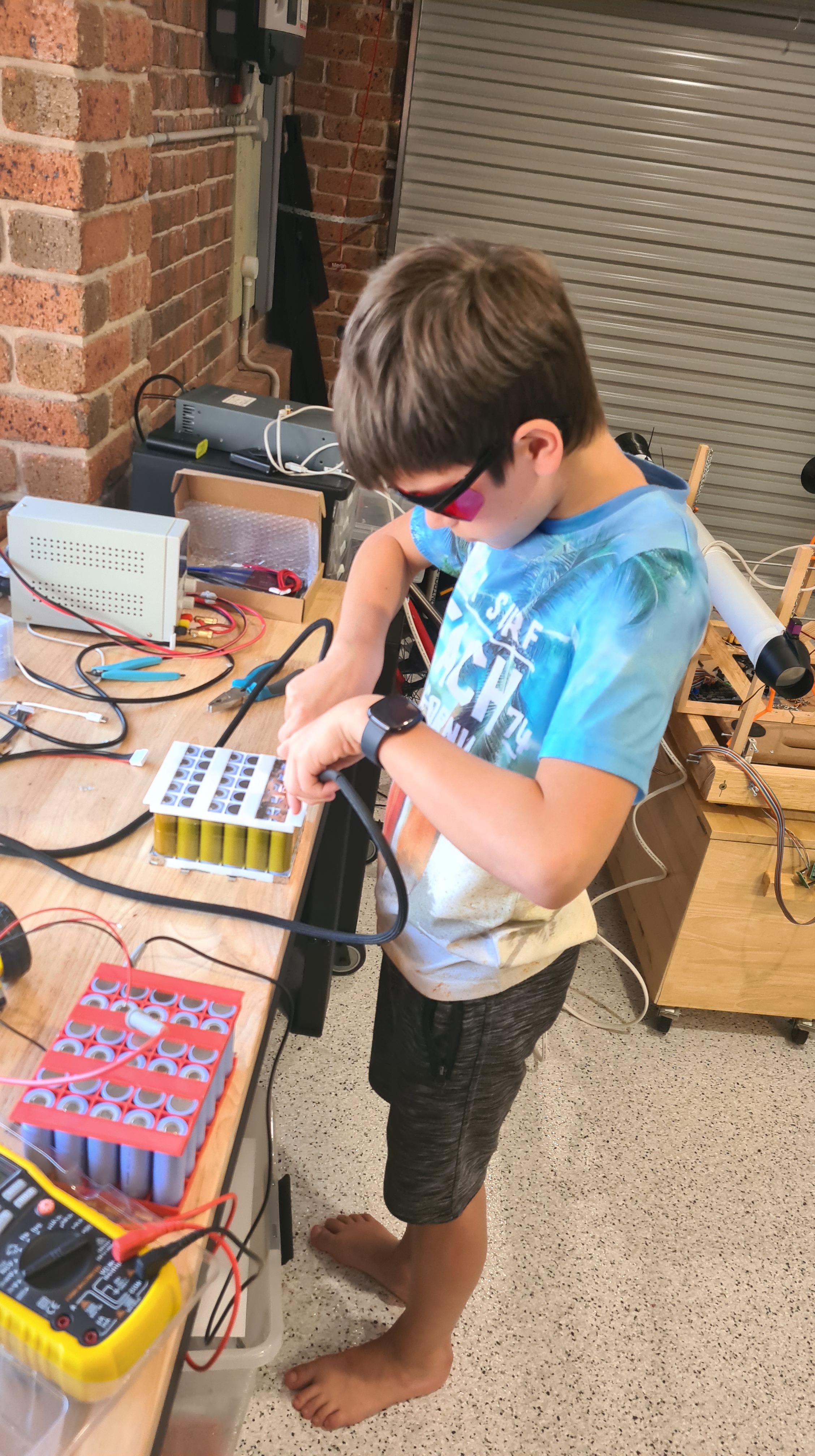
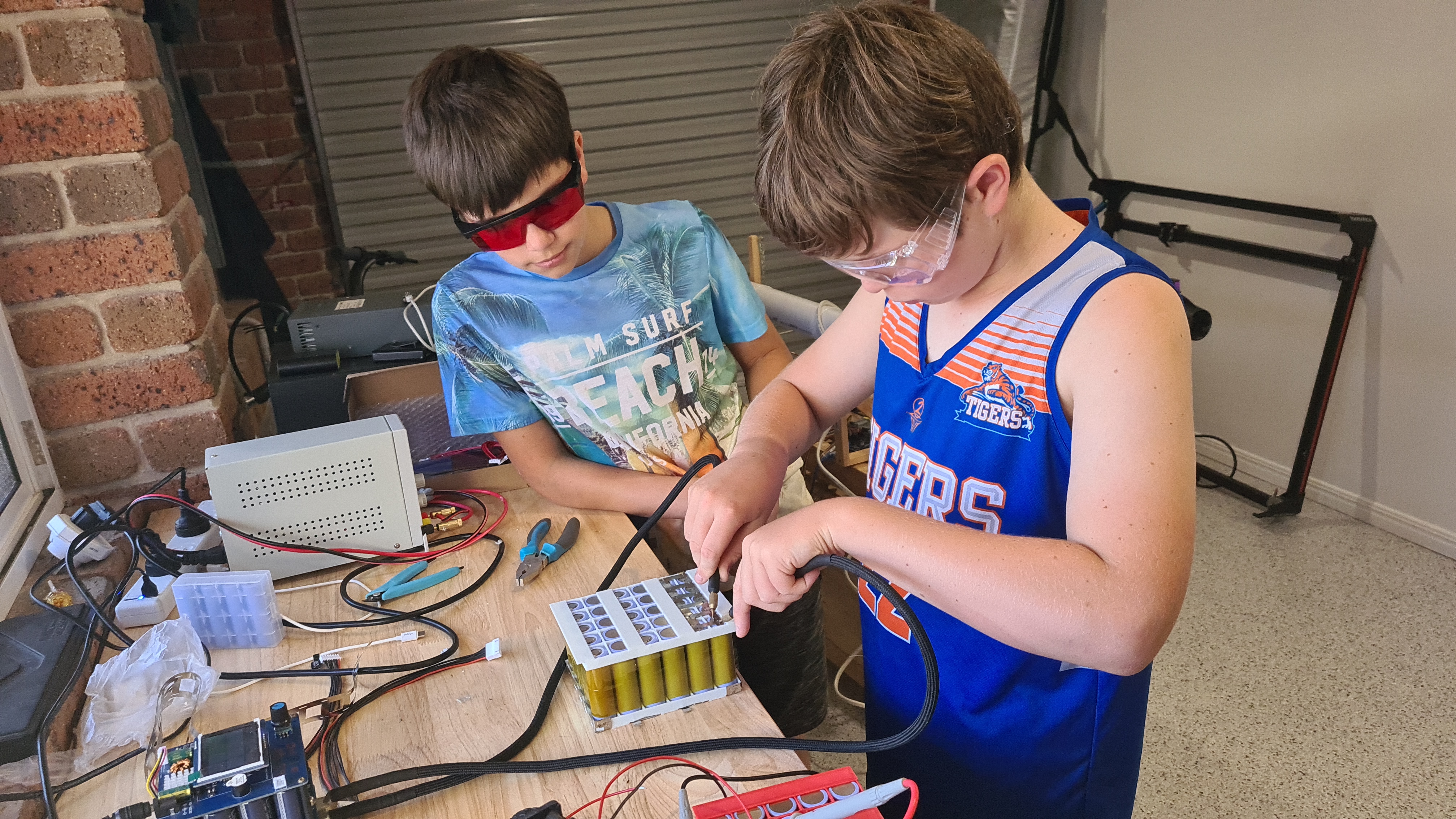


Boys were sort of enjoying it, and while Oli pretended that it is not his most favourite, he actually also did very good job! I also did a couple of videos, so there is an evidence that even kids can do this work.
Well, let’s wrap it up here as there were many more things happening, but I don’t want posts to be too long. Anyway, well done guys and to be continued …
I asked Sebi to provide some option to visualise forces read by those cells and gave him a brief idea what I had on my mind thinking that it will entertain him for some time. Meanwhile I took on my the Monkey-business job of the cable crimping.


Not too shabby, huh? 🙂
Anyway, before I’ve been able to finish my crimping task – Sebi reported his part done!
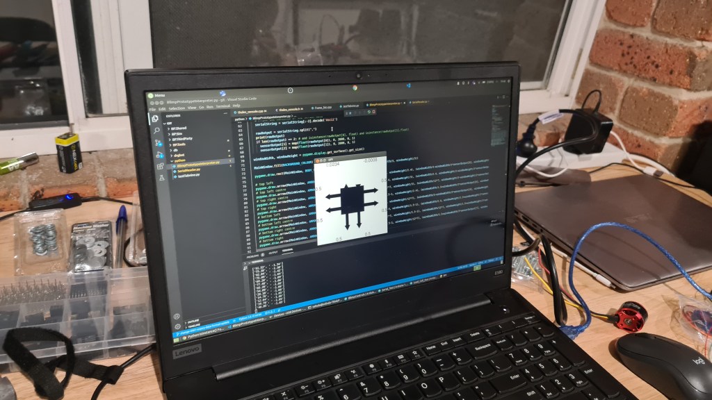
What you see on the picture above is simplified graphical interpretation of our testing rig with forces pulling in a corner. I’ve asked Sebi to tell you what’s going on in his words.
I took a picture of whole setup.
And asked Sebi to give away his Python and Arduino code (Python first).
import pygame
import math
from pygame.time import Clock
import serial

def map(value = float, fromStart = float, fromEnd = float, toStart = float, toEnd = float):
return toStart + (toEnd - toStart) * ((value - fromStart) / (fromEnd - fromStart))

# specifications

ARROW_HEAD_SCALE = 1
ARROW_LINE_SCALE = 1
TEXT_SCALE = 1
OUTPUT_DECIMALS = 4

BACKGROUND_COLOUR = (255, 255, 255)
ARROW_HEAD_COLOUR = (0,0,0)
ARROW_LINE_COLOUR = (0,0,0)
BODY_COLOUR = (0,0,0)
TEXT_COLOUR = (0,0,0)

TEXT_FONT = "arial"

pygame.init()
# of specific dimension..e(X, Y).
MainWindow = pygame.display.set_mode((0, 0),
                   pygame.RESIZABLE, pygame.FULLSCREEN)

pygame.font.init() # you have to call this at the start,
           # if you want to use this module.

# set the pygame window name
pygame.display.set_caption('BPI')

def arrow(screen, lcolour, tricolour, start, end, trirad, thickness=2):
  rad = math.pi/180
  pygame.draw.line(screen, lcolour, start, end, thickness)
  rotation = (math.atan2(start[1] - end[1], end[0] - start[0])) + math.pi/2
  pygame.draw.polygon(screen, tricolour, ((end[0] + trirad * math.sin(rotation),
                    end[1] + trirad * math.cos(rotation)),
                     (end[0] + trirad * math.sin(rotation - 120*rad),
                    end[1] + trirad * math.cos(rotation - 120*rad)),
                     (end[0] + trirad * math.sin(rotation + 120*rad),
                    end[1] + trirad * math.cos(rotation + 120*rad))))

setattr(pygame.draw, 'arrow', arrow)

sensorOutput = 8 * [0.5]

serialPort = serial.Serial(port = "/dev/ttyACM0", baudrate=9600,
                           bytesize=8, timeout=2, stopbits=serial.STOPBITS_ONE)

serialString = ""                           # Used to hold data coming over UART

# infinite loop
while True:
  if(serialPort.in_waiting > 0):
    # Read data out of the buffer until a carraige return / new line is found
    serialString = serialPort.readline()

    # Print the contents of the serial data
    serialString = serialString[:-2].decode('Ascii')

    rawOutput = serialString.split(",")
    print(rawOutput)
    if len(rawOutput) == 2: # and isinstance(rawOutput[0], float) and isinstance(rawOutput[1],float)
      sensorOutput[1] = map(float(rawOutput[0]), 0, 2000, 0, 1)
      sensorOutput[2] = map(float(rawOutput[1]), 0, 2000, 0, 1)

  windowWidth, windowHeight = pygame.display.get_surface().get_size()

  MainWindow.fill(BACKGROUND_COLOUR)

  pygame.draw.rect(MainWindow, BODY_COLOUR, (windowWidth/3, windowHeight/3, windowWidth/3, windowHeight/3))

  # top left
  pygame.draw.arrow(MainWindow, ARROW_LINE_COLOUR, ARROW_HEAD_COLOUR, (windowWidth/3, windowHeight/2.4), (windowWidth/3-windowWidth/3*sensorOutput[0], windowHeight/2.4), round(windowWidth/24)*ARROW_HEAD_SCALE, round(windowWidth/24)*ARROW_LINE_SCALE)
  # top left centre
  pygame.draw.arrow(MainWindow, ARROW_LINE_COLOUR, ARROW_HEAD_COLOUR, (windowWidth/2.4, windowHeight/3), (windowWidth/2.4, windowHeight/3-windowHeight/3*sensorOutput[1]), round(windowWidth/24)*ARROW_HEAD_SCALE, round(windowWidth/24)*ARROW_LINE_SCALE)
  # top right centre
  pygame.draw.arrow(MainWindow, ARROW_LINE_COLOUR, ARROW_HEAD_COLOUR, (windowWidth/12*7, windowHeight/3), (windowWidth/12*7, windowHeight/3-windowHeight/3*sensorOutput[2]), round(windowWidth/24)*ARROW_HEAD_SCALE, round(windowWidth/24)*ARROW_LINE_SCALE)
  # top right
  pygame.draw.arrow(MainWindow, ARROW_LINE_COLOUR, ARROW_HEAD_COLOUR, (windowWidth/1.5-1, windowHeight/2.4), (windowWidth/1.5+windowWidth/3*sensorOutput[6], windowHeight/2.4), round(windowWidth/24)*ARROW_HEAD_SCALE, round(windowWidth/24)*ARROW_LINE_SCALE)
  # bottom left
  pygame.draw.arrow(MainWindow, ARROW_LINE_COLOUR, ARROW_HEAD_COLOUR, (windowWidth/3, windowHeight/12*7), (windowWidth/3-windowWidth/3*sensorOutput[4], windowHeight/12*7), round(windowWidth/24)*ARROW_HEAD_SCALE, round(windowWidth/24)*ARROW_LINE_SCALE)
  # bottom left centre
  pygame.draw.arrow(MainWindow, ARROW_LINE_COLOUR, ARROW_HEAD_COLOUR, (windowWidth/2.4, windowHeight/1.5-1), (windowWidth/2.4, windowHeight/1.5+windowHeight/3*sensorOutput[5]), round(windowWidth/24)*ARROW_HEAD_SCALE, round(windowWidth/24)*ARROW_LINE_SCALE)
  # bottom right centre
  pygame.draw.arrow(MainWindow, ARROW_LINE_COLOUR, ARROW_HEAD_COLOUR, (windowWidth/12*7, windowHeight/1.5-1), (windowWidth/12*7, windowHeight/1.5+windowHeight/3*sensorOutput[3]), round(windowWidth/24)*ARROW_HEAD_SCALE, round(windowWidth/24)*ARROW_LINE_SCALE)
  # bottom right
  pygame.draw.arrow(MainWindow, ARROW_LINE_COLOUR, ARROW_HEAD_COLOUR, (windowWidth/1.5-1, windowHeight/12*7), (windowWidth/1.5+windowWidth/3*sensorOutput[7], windowHeight/12*7), round(windowWidth/24)*ARROW_HEAD_SCALE, round(windowWidth/24)*ARROW_LINE_SCALE)

  textFont = pygame.font.SysFont(TEXT_FONT, round((windowWidth/26)+(windowHeight/26)/2*TEXT_SCALE))

  topLeft = textFont.render(str(round(sensorOutput[0],OUTPUT_DECIMALS)), True, TEXT_COLOUR)
  topLeftCentre = textFont.render(str(round(sensorOutput[1],OUTPUT_DECIMALS)), True, TEXT_COLOUR)
  topRightCentre = textFont.render(str(round(sensorOutput[2],OUTPUT_DECIMALS)), True, TEXT_COLOUR)
  topRight = textFont.render(str(round(sensorOutput[3],OUTPUT_DECIMALS)), True, TEXT_COLOUR)
  bottomLeft = textFont.render(str(round(sensorOutput[4],OUTPUT_DECIMALS)), True, TEXT_COLOUR)
  bottomLeftCentre = textFont.render(str(round(sensorOutput[5],OUTPUT_DECIMALS)), True, TEXT_COLOUR)
  bottomRightCentre = textFont.render(str(round(sensorOutput[6],OUTPUT_DECIMALS)), True, TEXT_COLOUR)
  bottomRight = textFont.render(str(round(sensorOutput[7],OUTPUT_DECIMALS)), True, TEXT_COLOUR)

  MainWindow.blit(topLeft, dest=(0, windowHeight/3-topLeft.get_height()))
  MainWindow.blit(topLeftCentre, dest = (windowWidth/3-topLeftCentre.get_width(), 0))
  MainWindow.blit(topRightCentre, dest = (windowWidth/1.5, 0))
  MainWindow.blit(topRight, dest=(windowWidth-topRight.get_width(), windowHeight/3-topRight.get_height()))
  MainWindow.blit(bottomLeft, dest=(0, windowHeight/1.5))
  MainWindow.blit(bottomLeftCentre, dest=(windowWidth/3-bottomLeftCentre.get_width(), windowHeight-bottomLeftCentre.get_height()))
  MainWindow.blit(bottomRightCentre, dest=(windowWidth/1.5, windowHeight-bottomRightCentre.get_height()))
  MainWindow.blit(bottomRight, dest=(windowWidth-bottomRight.get_width(), windowHeight/1.5))

  pygame.display.update()
  Clock().tick_busy_loop(20)
Now Arduino
#include "HX711.h"

#define calibration_factor -21600 //This value is obtained using the SparkFun_HX711_Calibration sketch

#define LOADCELL_DOUT_PIN  3
#define LOADCELL_SCK_PIN  2

HX711 scale1;
HX711 scale2;

void setup() {
  Serial.begin(9600);
  Serial.println("HX711 scale demo");

  scale1.begin(3, 2);
  scale1.set_scale(calibration_factor); //This value is obtained by using the SparkFun_HX711_Calibration sketch
  scale1.tare(); //Assuming there is no weight on the scale at start up, reset the scale to 0
  scale2.begin(5, 4);
  scale2.set_scale(calibration_factor); //This value is obtained by using the SparkFun_HX711_Calibration sketch
  scale2.tare(); //Assuming there is no weight on the scale at start up, reset the scale to 0

  Serial.println("Readings:");
}

void loop() {
  String full = String(scale1.get_units()*10)+", "+String(scale2.get_units()*10);
  Serial.println(full);
  delay(100);
}
Pretty nice, isn’t it? As always, let us know what you think about it 😉
Couple months back I ordered from AliExpress set of Load Cell sensors for our testing rig project .

Those arrived in a good shape and while being pretty interested into how those work, it took us a bit to get to them.

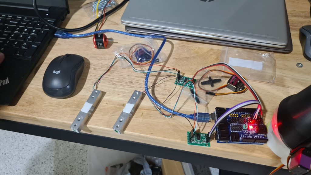
Sebi prepared a setup to give it a go. That aluminium thing is our load cell, it is connected to an amplifier, which is connected to some ArduinoNano and all that chain ends in Sebi’s laptop through USB. Each load cell comes with an arrow showing direction in which forces should be applied.
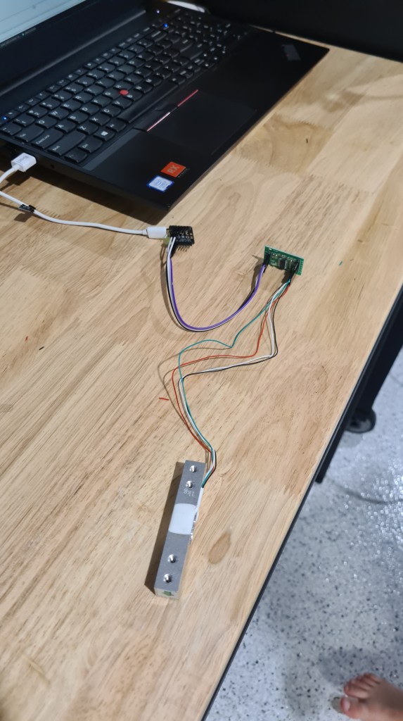
I’ve asked Sebi to describe it in his words.
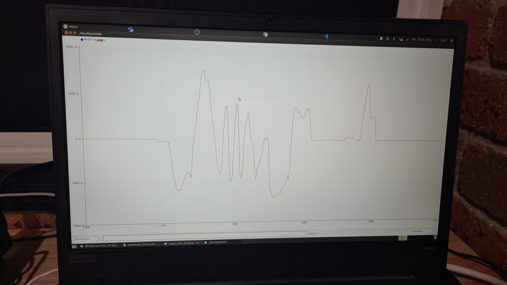
Seeing that video, I noticed that that final plot is probably not visible properly, so I took a close picture. Interestingly you can see positive and also negative values, that may come pretty handy. Also while that load cell says that it is up to 1kg (9.80665N) we’ve been seeing even higher values (1.2kg).
If you would be interested in reproducing the same, Sebi shared with me his source code.
#include "HX711.h"

#define calibration_factor -21600 //This value is obtained using the SparkFun_HX711_Calibration sketch

#define LOADCELL_DOUT_PIN  3
#define LOADCELL_SCK_PIN  2

HX711 scale;

void setup() {
  Serial.begin(9600);
  Serial.println("HX711 scale demo");

  scale.begin(LOADCELL_DOUT_PIN, LOADCELL_SCK_PIN);
  scale.set_scale(calibration_factor); //This value is obtained by using the SparkFun_HX711_Calibration sketch
  scale.tare(); //Assuming there is no weight on the scale at start up, reset the scale to 0

  Serial.println("Readings:");
}

void loop() {
  Serial.print("Reading: ");
  Serial.print(scale.get_units()*10, 1); //scale.get_units() returns a float
  Serial.print(" g"); //You can change this to kg but you'll need to refactor the calibration_factor
  Serial.println();
}
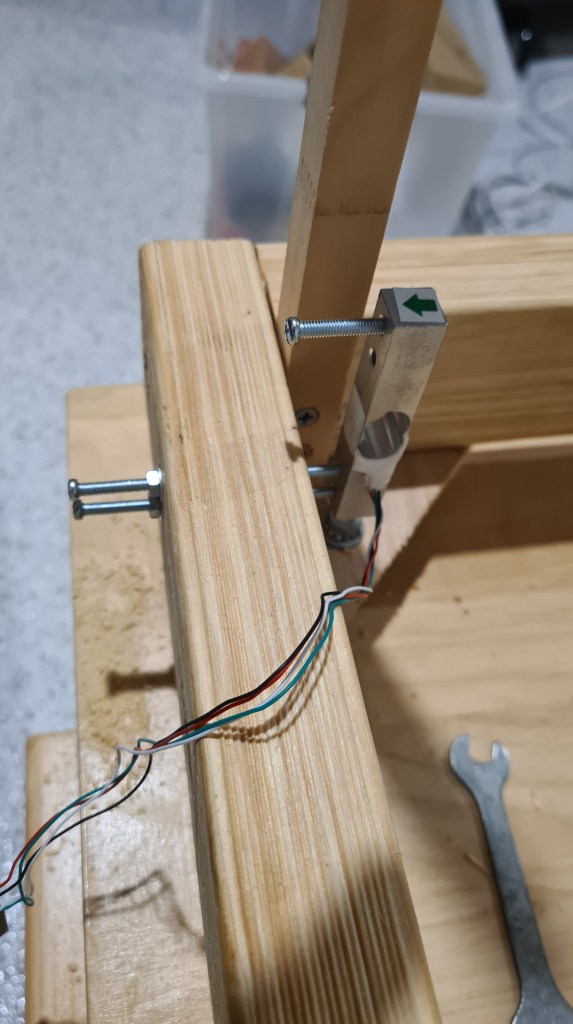
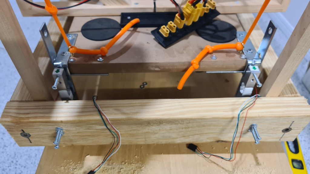
Now you probably wonder what it is for .. well here are few pictures to tune you up, but it is still work-in-progress so I’ll leave the rest for another article. 😉

So I think this was a pretty good progress for one day! So don’t forget to leave some message for Sebi – those motivate him a lot. 😉
One of the problems I can’t stop thinking about is how we are going to steer that airship. It is easy to do steering like we are doing it today – when we have just two motors and two vectored thrusters, but how’s that all going to look like with that plus 4 more gimbals? To see it all working I came with an idea of a test rig which would allow us to develop a control mechanics and test those easily.
It took a while to come from an idea to practicalities, but I’ve been finally able to explain all what I am looking for to Serge and we came with a plan:
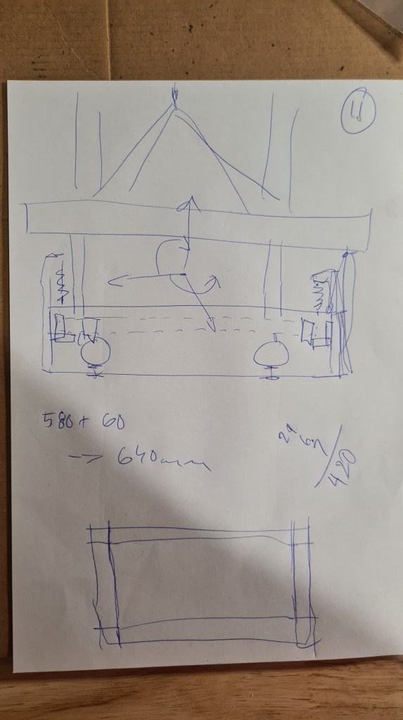

I understand that it looks bit wild now, but what you are looking at is our future testing rig. Just imagine a frame wider than our cart which surrounds it with multiple weight sensors on all sides. It also comes with a facility to balance whole cart in the air so all values the reads from sensors are not biased with any friction coming from wheels. Finally whole system is completely stationary and shouldn’t move at all so there is no need to reset it. Also whole system to be fed by that 2kW PSU (24V, up to 81A) which arrived couple weeks ago to mitigate any power fluctuations from batteries.
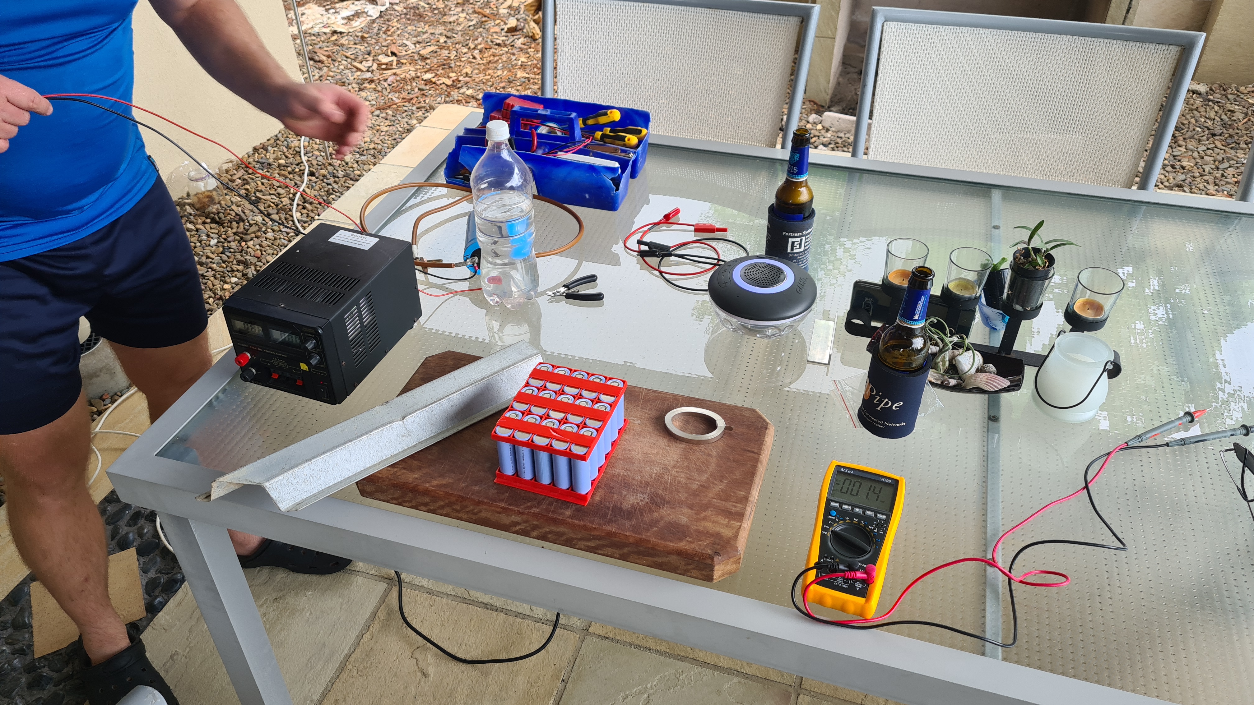
After agreeing with the plan with Serge, we went shopping – to local Bunnings store. It was cheaper than what I initially thought of.
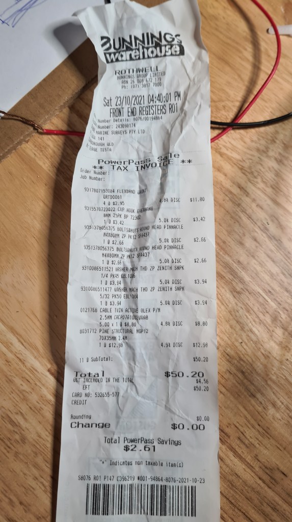
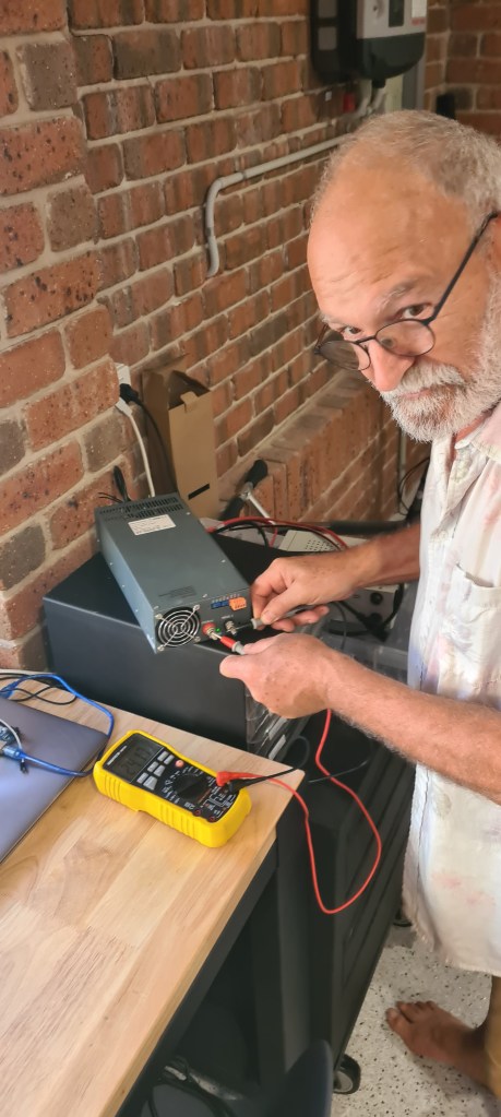
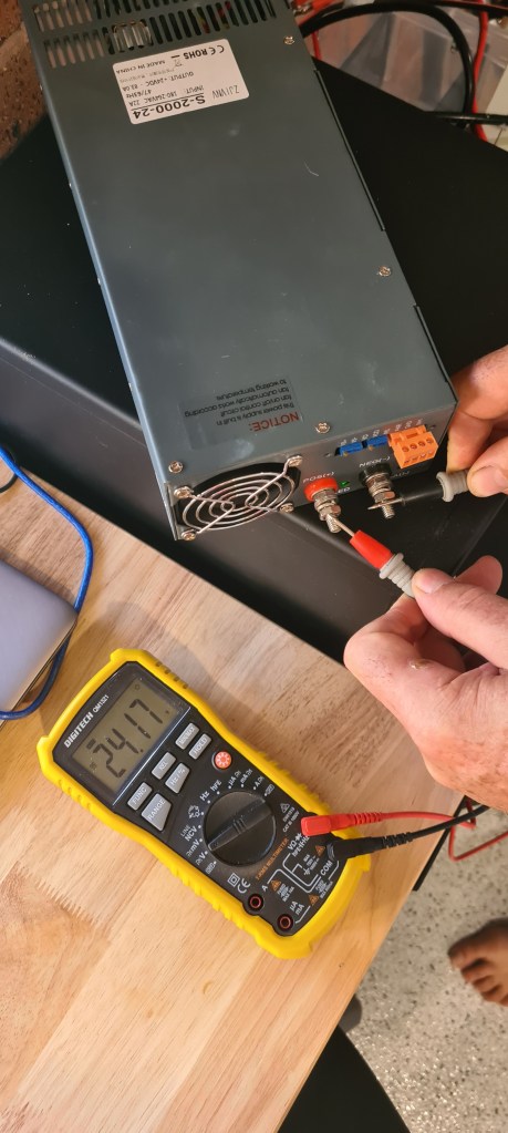
Surprisingly we didn’t start with the frame, but with the PSU. Serge quickly mounted power plug and I did bit of soldering with XT-90 to fit our power bridge. Multi-tool confirmed that have it all right – 24.17V. Same voltage came at the end of that 5m 2.5mm copper twin cable, what was quite relief as I was bit worried about some decline there.

Let’s see how is all that going to perform when feeding 6 motors on a full power. A screenshot from calculator below shows that it shouldn’t necessarily burn out.

Well, than it was lots of measuring, cutting and screwing – unfortunately we were so efficient that I forgot to take pictures. I took few afterwards. The first one gives a good overview on what we achieved. There firm frame with posts and rubber bands.

The same, but upside down – showing glued triangles to provide some structural stability and adjustable legs.

Finally with our cart fitted in it.

A detail of the rubber band hanging from the post and lifting our cart.
Now couple more pictures to provide better perspective on how it looks.


You can notice that those rubber bands are not holding it exactly in a center of that rig. I am still working on that, but whole system is perfectly sensitive and responding nicely to all external influences. Sebi demonstrates on video below.
Watching that video above again I also think that all that cart should be hanging higher, but that’s again something to solve whilst we’ll be mounting sensors.
Finally Sebi wanted to see how it all works with engines, unfortunately our right engine and both vectors are currently under service (undertaking a planned upgrade 😉 ) so we had just the left one to go with. Anyway I was curious as well as that will be also premiere for our new super-beefy PSU.
I think it’s awesome! There is a clear and demonstrable push / pull from that motor on a whole system and I can’t wait to see all that being measured with our load sensors. 🙂
We’ve progressed with Sebi on those through the day and did much more, but as we haven’t finished I’ll keep it for another post.
Huge thanks to Serge and Sebi for helping me for a whole weekend and I hope you all enjoyed seeing some serious progress we are doing lately. As always feel free to post any comments and ideas, those are always welcome and provide us with motivation to keep going. 😉
After quite a while I am happy that I can report some progress on our original Battery pack project. As the first, I’ve been able to raise some money from my sponsor (Veronika) and bought 60 of these:

As you can read in my previous article – they were $11 originally, but after while their price suddenly dropped to $4.75. No idea what’s behind it, but they arrived practically instantly – delivered by the FUBU guy himself.

And also we weighted one cell for reference – one cell weights 74g.

Meanwhile I started working on the battery pack frame. Using quite a simplified 2S2P design I came up with this code, which allows S & P parameters together with battery size option to print what’s needed.
use <ShortCuts.scad>

// Config
S = 2;
P = 2;
wall_thickness = 1;
wall_height = 8;
/*
 * Battery types
 * A = 18650
 * B = 21700
 */
battery_type = "B";
material_buffer = 1;
top = false;

function battery_d()
  = battery_type == "A"? 18 + material_buffer:21 + material_buffer;

function box_x() = P*(wall_thickness + battery_d()) + wall_thickness;
function box_y() = S*(wall_thickness + battery_d())+ wall_thickness;

function sep_x() = P*(wall_thickness + battery_d()/3) + wall_thickness;

module wall_x(x) {
  T(0, x*(battery_d() + wall_thickness), 0)
  minkowski() {
    cube([box_x() - wall_thickness/2,wall_thickness/2,wall_height], center = false);
    sphere(wall_thickness/2);
  }
}

module wall_y(y) {
  T(y*(battery_d() + wall_thickness), 0, 0)
  minkowski() {
    cube([wall_thickness/2,box_y() - wall_thickness/2,wall_height], center = false);
    sphere(wall_thickness/2);
  }
}

module separator(x) {
  if (x%2 && top)
  T(0, x*(battery_d() + wall_thickness) - battery_d()/3, -wall_thickness)
  minkowski() {
    cube([box_x()-wall_thickness/2,(battery_d()*2/3 + wall_thickness),wall_thickness/2], center = false);
    sphere(wall_thickness/2);
  }

  if ((x-1)%2 && !top)
  T(0, x*(battery_d() + wall_thickness) - battery_d()/3, -wall_thickness)
  minkowski() {
    cube([box_x()-wall_thickness/2,(battery_d()*2/3),wall_thickness/2], center = false);
    sphere(wall_thickness/2);
  }
}

$fn=30;

//walls
for(x = [0:S]) wall_x(x);
for(y = [0:P]) wall_y(y);

//separators
for(x = [0:S]) separator(x);
This code translates to this beauty:
So I kept changing the code, rendering, slicing …

…printing …
… and testing. What looked initially like a trivial task still took a while (days) to get it right. All that below is just garbage.
Until today finally – voila! After quite lengthy print (13hrs), all clicked together and with a bit of help from Sebi we made it in a tiny DIY animation.


Weighted it properly, showing that our new baby 6S5P battery comes to 2.28kg.

And I took one last picture just to show off 😉
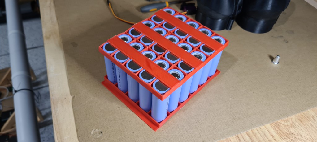
That’s all for today. Next stage is to get our nickel strips and a spot welder and let it all to click together. I can’t wait to see it all working!
So as per our first try a week ago – we reached the point where we’ve been moving forward without any cables, but I had to dismount vectors as they propellers were unable to push enough pressure to overcome their resistance. Well a week later – and doubled number of blades on propellers – here we go! And it looks awesome!
Where next? I wonder if its going to go on a street and for how long? 😛
It was a big weekend – lot’s of moving around the house, making 3D printer to print again and finally putting it all together! We did multiple runs, but this one was the best in limited conditions we had.
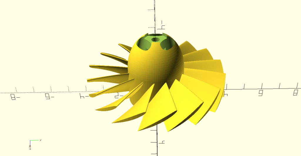
You may notice that vectors are not mounted – interestingly we haven’t been able to make it moving with vectors on. I think that problem might be that our turbine comes with too few blades (8) to properly push against those vectors.

So I doubled those (16) and it is printing just now for another test. Still, it will take probably couple days as one of these complex prints take ~6hrs and as I wan’t layers to stick together properly I am printing with 66% speed only (~10hrs).
Still, I think it is a great progress forward, don’t you think? We are finally moving with everything loaded on a cart – batteries, controllers, receiver. I am feeling so good about it 🙂
Progressing slowly these days, Sebi made quite few steps forward on his own. Starting with that Dual Shock 2 integration, he bought Turnigy TGY-iA6B V2 Receiver 6CH 2.4G AFHDS 2A Telemetry Receiver w/SBUS from Hobby King in expectation to extend control range significantly.

It took it more than a month to arrive, but Sebi couldn’t resist to mount it:
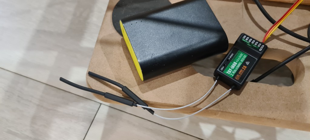
The other cable’s ended up in Arduino MEGA’s sensor shield.
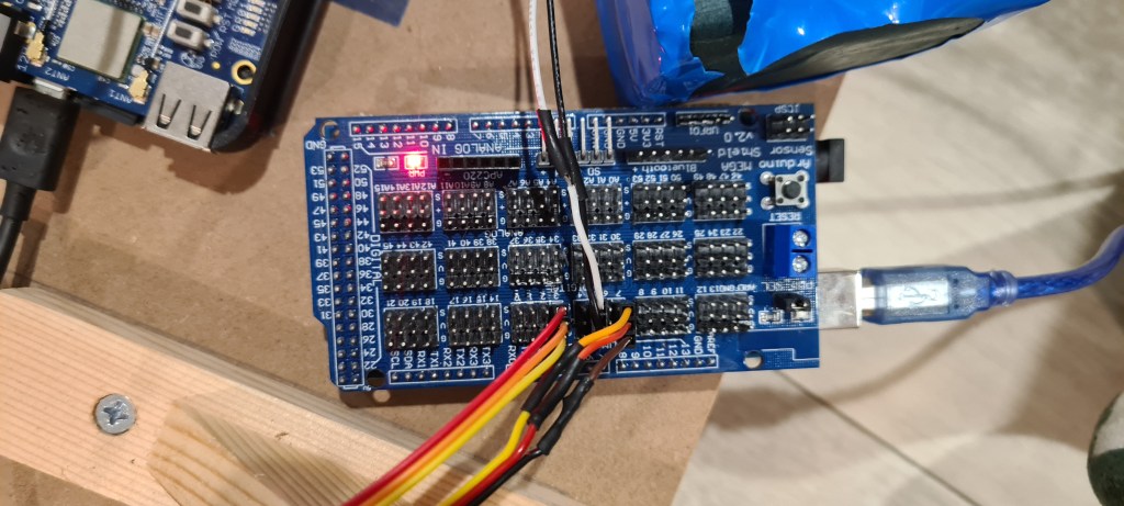
And of course huge thanks to Simon for donating his Turnigy TGY-i6 Mode 2 AFHDS Transmitter and 6CH Receiver.
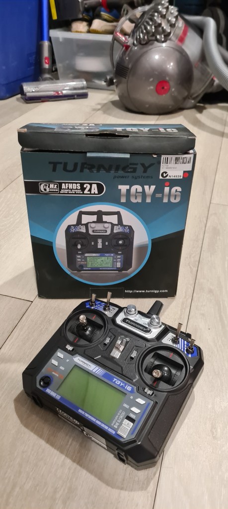
Sebi kept coding whole day and while being pretty desperate time to time he ended up with having it done! His code follows (all just Sebi!!).
// Needs to have PPM-reader installed: it works on avr arduinos
#include <PPMReader.h>
#include <Servo.h>

// Initialize a PPMReader on digital pin 3 with 6 expected channels.
int channelAmount = 6;
PPMReader ppm(3, channelAmount);

// Declaring some basic variables.
int channel;          //channel index
int value;            //value variable
int bufferValues[6];  //memory buffer
int values[6];        //value memory
int minValue = 1000;  //minValue option

//Starting up the servo objects
Servo thrusters;
Servo vectors;

void setup() {
  Serial.begin(115200);
  thrusters.attach(4);
  vectors.attach(7);
}

void loop() {
  // I use a 'loop' because 'for' doesn't comply sometimes
  channel = 1;
  while (channel <= channelAmount) {
    int value = ppm.latestValidChannelValue(channel, 0); //saves value
    // this operation simple reverts the value back if it crosses the min
    if (value < minValue) {
      value = bufferValues[channel];
    } else {
      // and saves it otherwise
      bufferValues[channel] = value;
    }
    // then that is all put over an extra layer of security
    if (value < minValue) {
      value = 1000;
    }
    // here I utilise the map function to condition the channels
    if (channel != 5 and channel != 6) {
      value = map(value, 1100, 1990, 1000, 2000);
    }
    values[channel] = value;
    Serial.print(String(value) + "\t");
    channel++;
  }
  // this operation asks whether the switch is on
  if (values[6] > 1500) {
    thrusters.writeMicroseconds(values[3]);
    vectors.writeMicroseconds(values[4]);

  } else {
    thrusters.writeMicroseconds(1000);
    vectors.writeMicroseconds(1500);
  }
  Serial.println();
  // here is the servo update delay
  delay(20);
}
Sebi also prepared a short demo on how it works.
Well done Sebi!
Next step – move it from Arduino to our BBBlue. 😉
EDIT 2025/08/04: Information in this post has been corrected here. Article below is still valid, but doesn’t account for the Effusion (process in which a gas escapes from a container through a hole of diameter considerably smaller than the mean free path of the molecules).
I am frequently being asked a question why I prefer Hydrogen above Helium – and I am always using their atom sizes as one of the main arguments for Hydrogen (being bigger -> less leaky) being more economic. Well, it came to me that I never actually checked what sizes they are!
As always, my big friend Wikipedia, instantly provided me with answers I needed…. and more. So many citations below come from there. I am trying to quote where not it is exact citation, but basically whole article is a more or less a compilation of texts from there. So thank you Wikipedia!
Let’s start with Hydrogen – Hydrogen is the chemical element with the symbol H and atomic number 1. Hydrogen is also the lightest element. At standard conditions hydrogen is a gas of diatomic molecules having the formula H2 (very important here). It is colorless, odorless, non-toxic, and highly combustible.
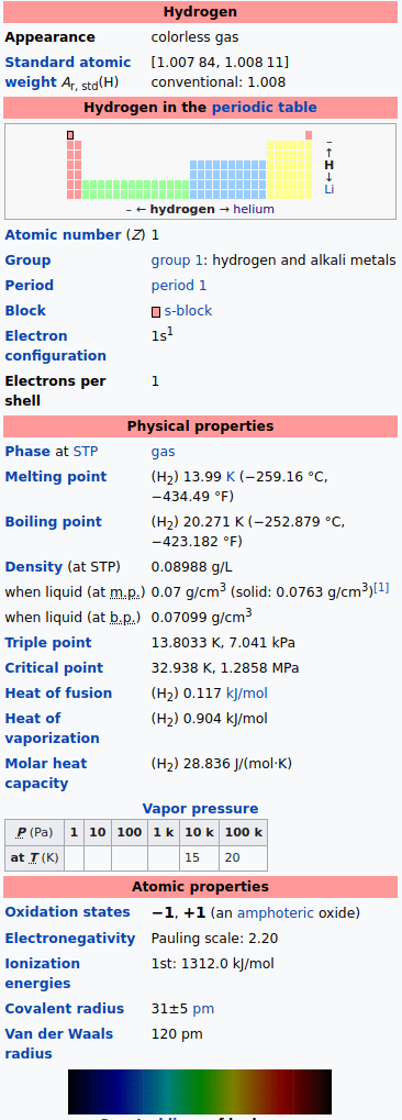
Our second competitor here is Helium – Helium is a chemical element with the symbol He and atomic number 2.
Helium’s natural occurrence is stated as Primordial nuclide – which are nuclides found on Earth that have existed in their current form since before Earth was formed and while while being the smallest and the lightest noble gas it is also one of the most unreactive elements we know so far (nonrenewable). It actually was commonly considered for a long time that helium compounds cannot exist at all, or at least not under normal conditions.

Unfortunately the value we need the most, cannot be found there, so I needed to keep searching for their Kinetic Diameter.
Kinetic diameter is a measure applied to atoms and molecules that expresses the likelihood that a molecule in a gas will collide with another molecule.
Wikipedia
Reading through that article you can see that Hydrogen (H2 molecule) comes with its kinetic diameter of 289pm (picometre), while Helium has “just” 260pm. Hydrogen molecule is 11% bigger than Helium. What this means for us? A lot! This actually explains why US airships (filled with Helium) were not flying to Europe and German Zeppelins (Hydrogen2) did many trans-Atlantic trips.
Problem was that Helium was leaking so fast through the Zeppelin’s envelope that they couldn’t carry enough of its canisters to refill it. Having Hydrogen being 6% lighter is just a nice bonus on top of it. 😉
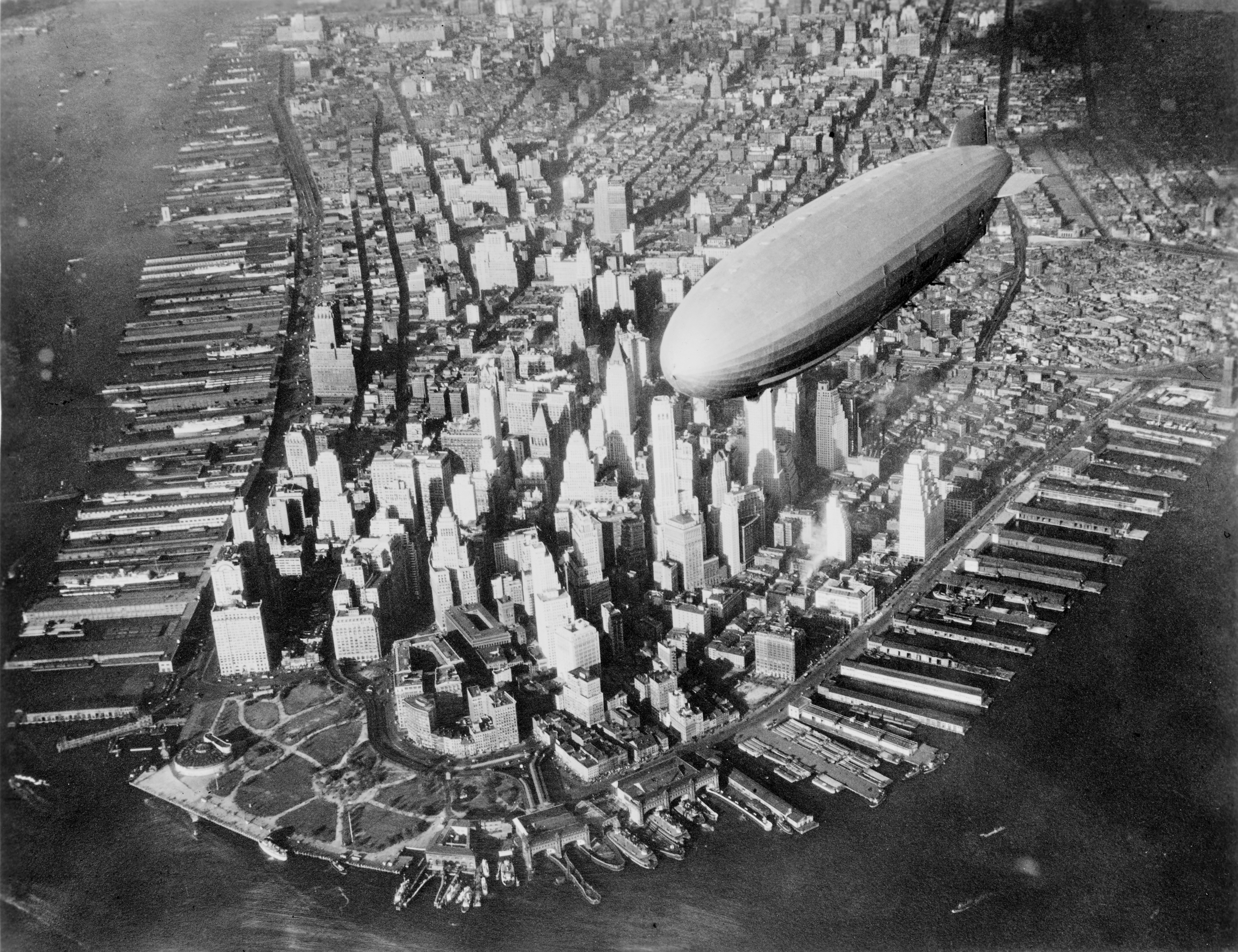
Addendum (2024/02/28): The Impact of Temperature on Gas Permeability
Recent inquiries have highlighted an important aspect of gas behavior relevant to airship technology—the effect of temperature on the permeability of gases like helium and hydrogen through containment materials. As temperature increases, the kinetic energy of gas molecules also rises, leading to more frequent and forceful collisions with the fabric of the containment material. This heightened activity can increase the likelihood of gas molecules escaping through microscopic imperfections in the material, thus elevating the permeability.

This phenomenon underscores the importance of selecting materials that not only account for the inherent properties of the gases, such as atom size discussed in this article, but also their interaction with temperature variations. Understanding and mitigating these effects are crucial for enhancing the efficiency and longevity of airship envelopes, ensuring that they remain less permeable and more resilient under a range of operational temperatures.
I bring a quite an interesting story today. I’ve been busy over the weekend and did a proper tidy-up on a whole power distribution and also fixed few bugs on our devices (vector thruster had a broken axle). I ended up with all being pretty ready for a hot-fire test.

Thinking to give it a go, I wrote a tiny C program to wiggle with both those thrusters.
#include <rc/servo.h>
#include <iostream>
#include <chrono>
#include <thread>
#include <random>

int main(int, char**) {

  std::random_device rd;
  std::mt19937 rng(rd());
  std::uniform_real_distribution<> uni(-1,1);

  std::cerr << "Init" << std::endl;
  rc_servo_init();

  std::cerr << "Turning On 6V Servo Power Rail" << std::endl;
  rc_servo_power_rail_en(1);

  while (true) {
    auto r = uni(rng);
    std::cerr << "r: " << r << std::endl;
    int i = 5;
    while(--i) {
      rc_servo_send_pulse_normalized(1, r);
      rc_servo_send_pulse_normalized(2, r);
      std::this_thread::sleep_for(std::chrono::milliseconds(200) );
    }
  }

  // turn off power rail and cleanup
  rc_servo_power_rail_en(0);
  rc_servo_cleanup();

  return 0;
}
.. .and because it wasn’t working I asked Sebi to fix it for me and went to do something else. Sebi fixed it by adding those two lines in bold (to initiate BBB’s power rails to feed servos) and told me its ready. It took me couple hours to come back to it, but by that time BBB started complaining about its file system being in a read-only mode and I couldn’t do much except to reboot it.
Unfortunately it never made it back to life. If it would be MS Windows I would probably see something like this:

.. but as it was “just” a BBB I saw just a dead piece of a microelectronic which’ LED ever second blink. Being bit upset about all that situation I went to sleep. I’ve been also hoping that when I’ll come next morning that problem will disappear (it really happened before!), but it didn’t. BBB was dead next morning in a same way like the night before. So I started Googling where next with that and found that there is an option to connect a serial cable to the UT0 slot and observe whole powering sequence and also interact with BBB on a lower level, but that needed a serial cable!
Googling again – found out one from China for $6, but delivery time was Christmas – next year – maybe. Luckily local Altronic store had exactly what I needed for still bearable $25. My way went straight in and I became a proud owner of the Z6522A • FT232 USB To TTL Serial Lead.
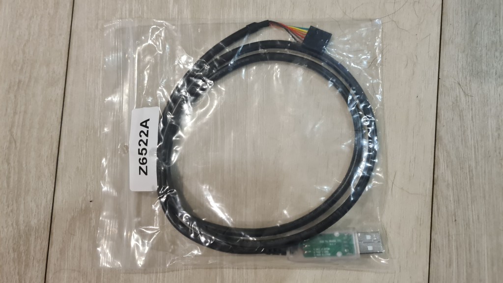
Next day I dedicated morning to some taping-magic (there was no time for proper soldering) and I was able to connect it with our BBB through the JST-SH connector which coincidentally arrived to Sebi a day before (it was on its way from China for a month). I am not proud of it, but here comes a picture whilst it is already connected.
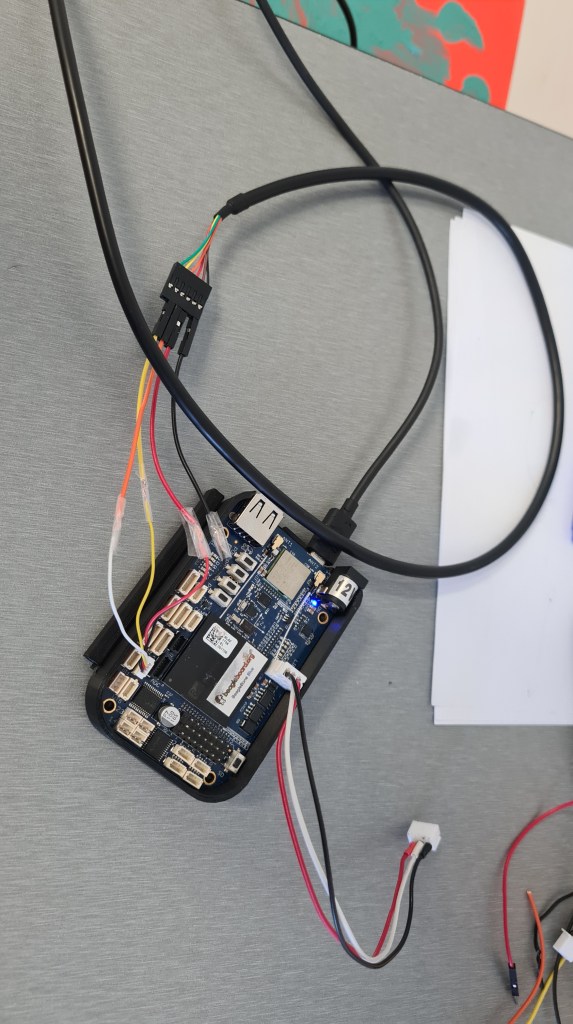
I hastily followed that original guide, but at that stage where I was expecting to see the login prompt to BBB – there was nothing.
blech@zenith$ ls -ls /dev/ttyUSB0
0 crw-rw---- 1 root dialout 188, 0 Sep 13 08:36 /dev/ttyUSB0
blech@zenith$ sudo adduser $USER dialout
blech@zenith$ sudo screen /dev/ttyUSB0 115200
<nothing>
I tried all slots, mutiple resets, adding battery, multiple configurations … very upsetting noting. So I called Andrew (who coincidentally received his own BBB a night before – but from Melbourne – in 4 days) and gave him everything to compare it with his brand new one. It took Andrew exactly 10 hours to come back with a great news – SD and eMMC images are wrong (BBB is ok).

Andrew replaced eMMC image on our BBB and returned it to my hands next day morning. I couldn’t wait to see it really working, but it still took couple hours to get it back where it was before. Still I couldn’t resist seeing it working and was happy where it started to do its first Vectoring thrusters dance. 🙂
Pretty funny, isn’t it?
However huge thanks to Andrew for saving me again!

And what was wrong with that cable? Apparently it is a 5V cable, where BBBlue has 3.3V serial interface which malfunctions under 5V. So I plan another trip to Altronics – but this time I’ll be asking for a refund. 😦
Anyway, all back to normal – next step is to see motors running on 25V!
After the previous success with asking Can I legally operate airship-drone in Queensland?, I went back to CASA asking what they think about filling the airship with Hydrogen.
Unfortunately I haven’t saved my inquiry and answer came without quoting it, but I still like it a lot as where you can see “may not permit” it could also come with “is not permitted” which is obviously much harder to deal with. 🙂

So I bought this “Ebike Battery Pack 24v 30ah Electric Motor Bike Bicycle Lithium Ion“.
It arrived reasonably fast (a month) and made me pretty happy.

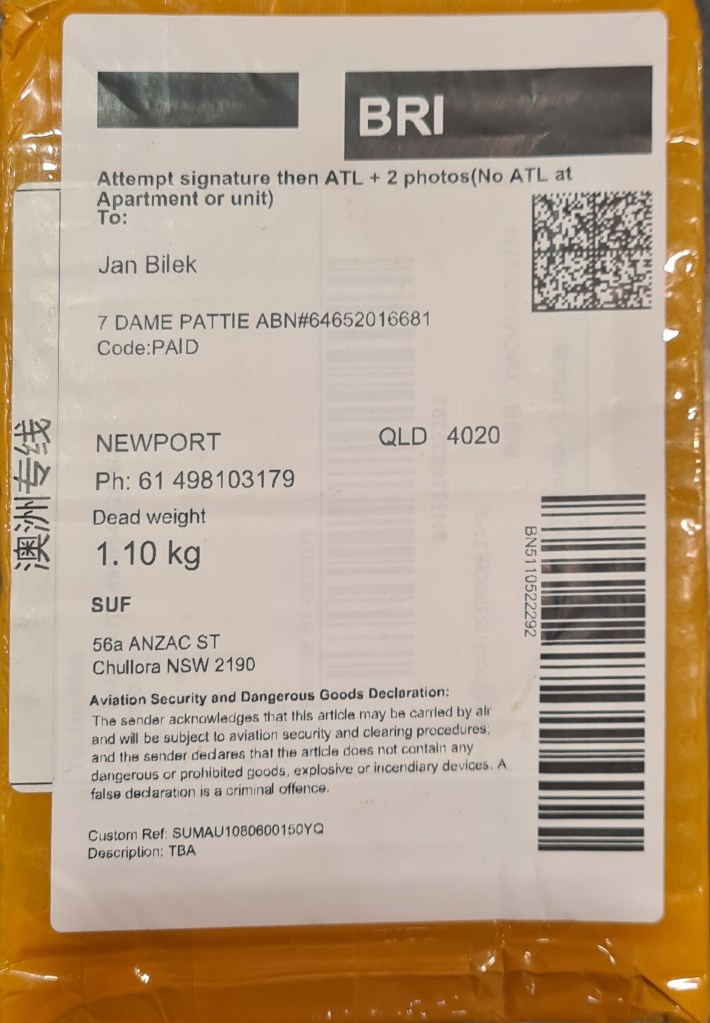

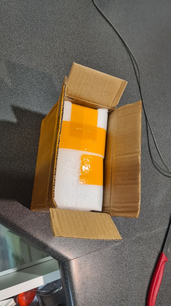
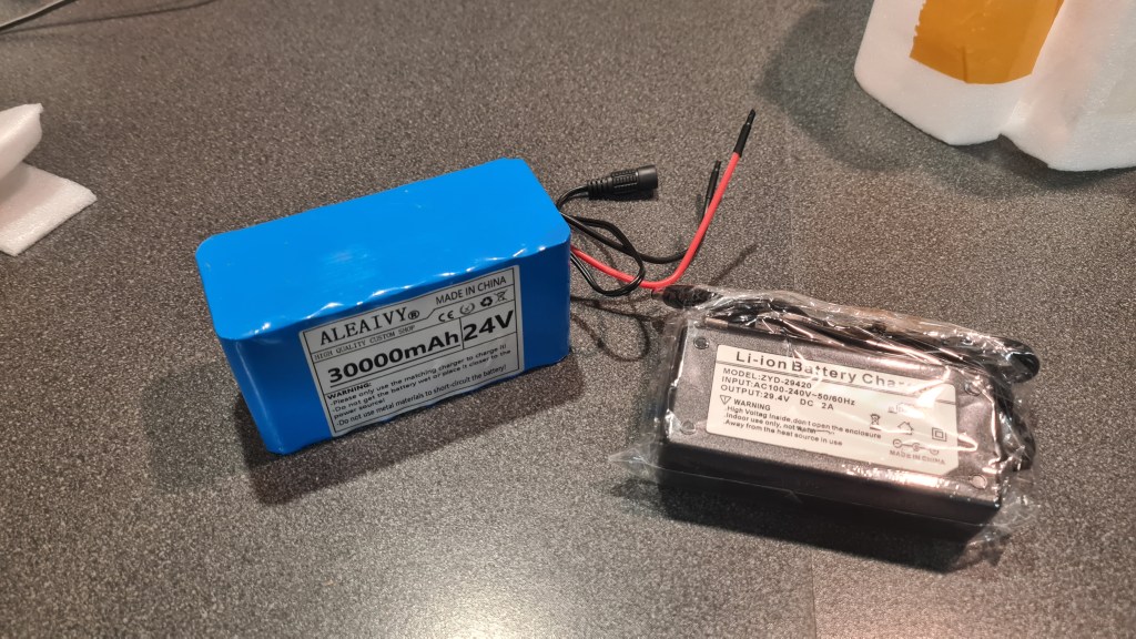

So happy that I went straight to Risa and gave it to him to check how is it doing. As you can see on the picture below, Risa ran a continuous discharge test (actually he ran multiple tests) which demonstrated that this battery has only 3.43Ah capacity in comparison to advertised 30Ah.


Richard then first did Balance on battery, and then charged 1A 6S. After checking voltage he sees it drop quickly to 24V. Now he restarted charging at 0.3A, low and slow to get more capacity before it gets destroyed on a 1A discharge cycle to determine new capacity.

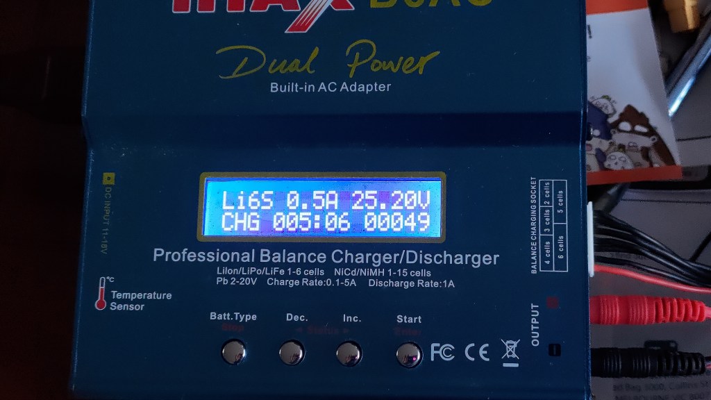
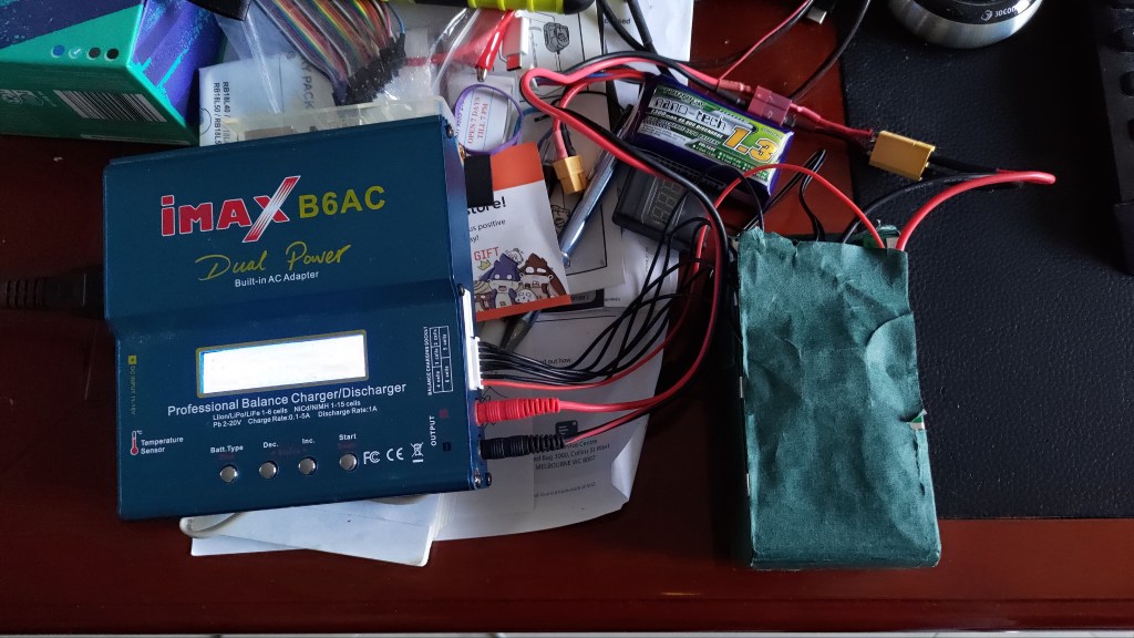
And it took another day to get a final result for our “brand new” 6S battery pack.
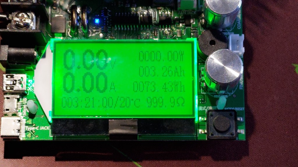
So final power balance sheet for our “Ebike Battery Pack 24v 30ah Electric Motor Bike Bicycle Lithium Ion with Charger – twisted into 6S” is:
If I’ll go full power – 2x 10A x 24V -> 480W
74Wh/ 480W -> 0.15h ~> 10mins drive.
I suppose the “no full power” option should get us to some 15-20 minutes.
Experiencing propeller to sleeve away from our motor after our latest power up, I’ve decided to implement that propeller clamp which came with motors.

Not to waste too much filament on the prototype, I did changes and rendered for printing the propeller nose only.
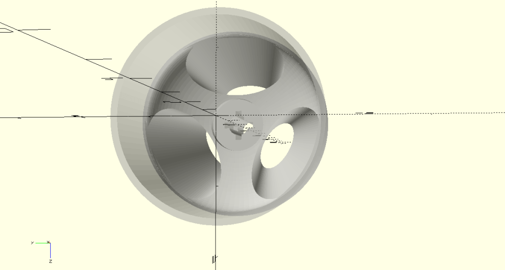


Printing took about an hour, extending the axle hole few more minutes.
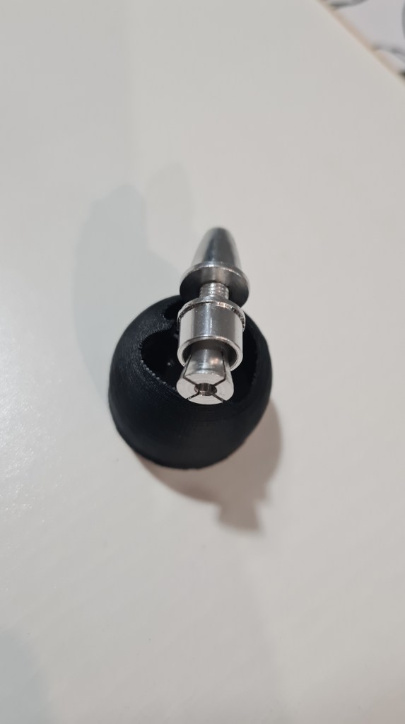

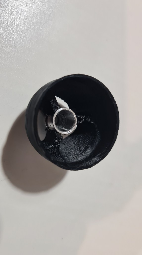
Screwed on top of the motor it felt pretty strong and I couldn’t take it off with my bare hands.

Seeing this as a success, I did couple more adjustments and rendered whole propeller.
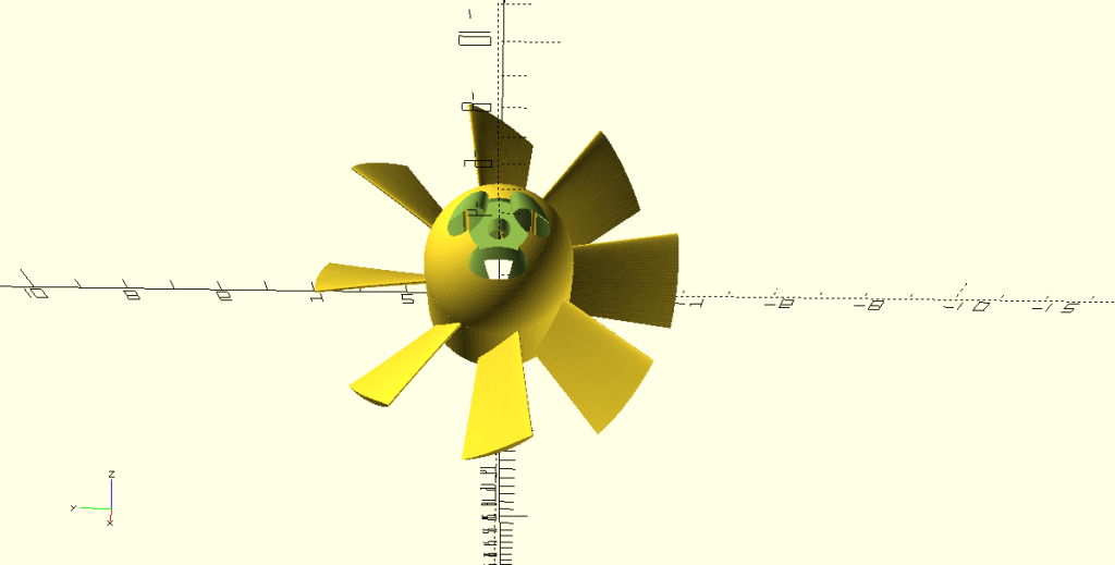
… actually two of them, so we can print those in one go.

Printing went easy – ABS on 250C tool / 110C bed + 60% speed.

Printed propellers came out almost perfect.

I couldn’t wait to see that all mounted so I did a dirty-mount – just to take another picture.
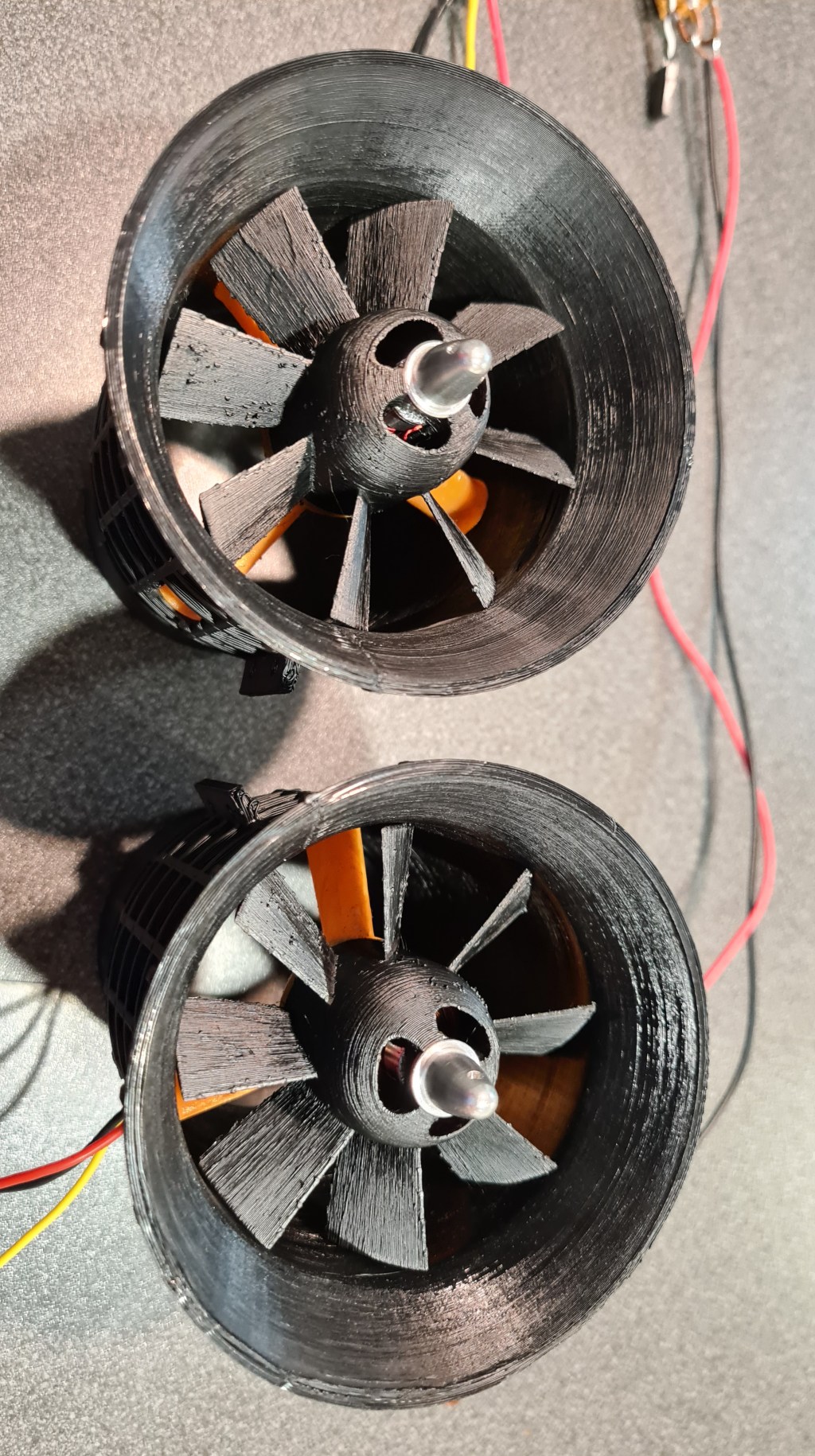
For comparison I am adding an 400W EDF I saw in a shop – this one was for $150.


I think that we made it pretty close. 🙂
To stay in touch through our team and community I’ve prepared a Discord server with some channels – hopefully covering some of our main topics there.

What is Discord?
Discord is a VoIP, instant messaging and digital distribution platform designed for creating communities. Users communicate with voice calls, video calls, text messaging, media and files in private chats or as part of communities called “servers”. Servers are a collection of persistent chat rooms and voice chat channels. Discord runs on Windows, macOS, Android, iOS, iPadOS, Linux, and in web browsers. As of December 2020, the service has over 250 million registered users and over 140 million monthly active users.
Wikipedia

Andrew forwarded me another awesome article called “Bring back hydrogen lifting gas” written by Eli Dourado from Utah State University.
I can recommend reading through it as a whole, but I made some notes for myself which I would like to comment on.
1/ Eli thinks that there is market for thousands of airships out there – I strongly agree!
Why does this matter if there are only 25 blimps in service today? Because it is still possible that, under more suitable rules, there is a market for thousands of airships.
Eli Dourado – Bring back hydrogen lifting gas
2/ Eli agrees with me that if all those economics should work out – Hydrogen is the way.
This difference in gross lift is non-trivial for airship performance, but by far the bigger effect of helium on airship economics is cost.
Eli Dourado – Bring back hydrogen lifting gas
3/ Eli also thinks that comeback can be achieved through the cargo service, while thinks that they are slow for human travel. Well, this is where I think that offering a luxurious travel service in a style of a land-style cruise(air)ship actually also has a big potential.
If airships were to make a major comeback, it would be in cargo service. Airships are too slow for human travel, but cargo containers don’t get fatigued on long flights.
Eli Dourado – Bring back hydrogen lifting gas
4/ Finally Eli elaborates on problems with FAA (Airship design approvals from 1995) – being a major obstacle in putting such ideas to life in the US.

But with decades of guidance to the contrary, the FAA has discouraged the return of the airship in the use case that makes the most sense. The only way to get an answer to the hydrogen question is to invest millions of dollars in starting an airship program and engaging the FAA on a certification basis. In turn, investors shy away from regulatory risk, especially when it falls outside their area of expertise.
Eli Dourado – Bring back hydrogen lifting gas
… well, but we are not in the US! We are in Australia and as far as I know there was no Hydrogen airship visiting ever.
Checking CASA’s website there is nothing about this topic, so I wrote them an inquiry through the available form. Unfortunately they don’t forward a copy of an original text so I am providing a receipt which I received afterwards.
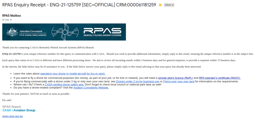
Now let’s wait 🙂

I contacted Eli Dourado over LinkedIn, sort of asking for a permission to quote his article + get back to me with any comments he might have. Eli came back shortly with following:
Thank you Eli!
Coming from multiple sources (Mick & Andrew) these guys are doing an amazing job: BUOYANT.
More reading here:
In preparation of our power upgrade I bought a new electronic speed controller – SPEDIX ES30HV 30A 3-6S BLHELI_S ESC .

It arrived quickly.

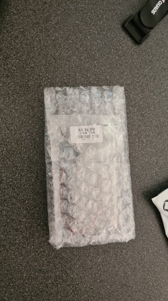
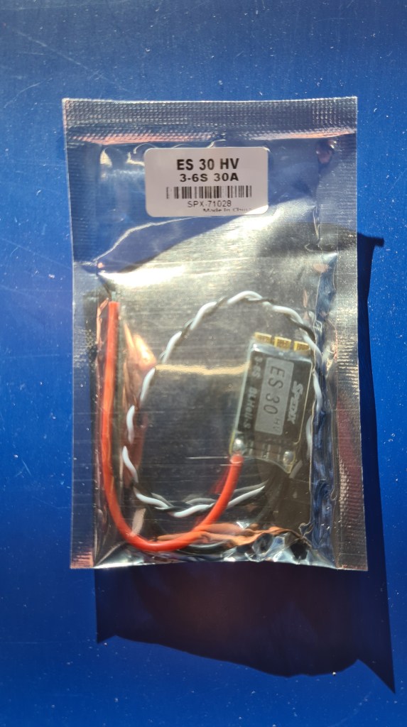
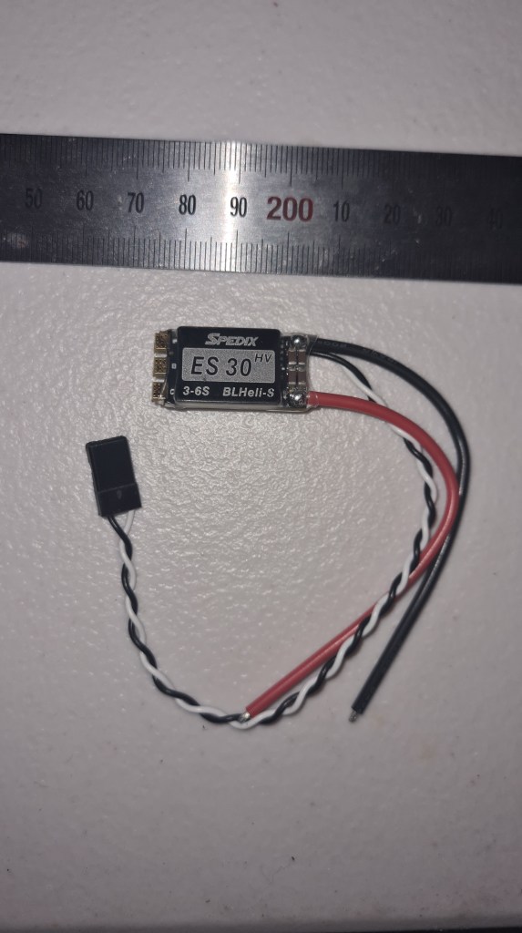
Soldering went well and we couldn’t wait to test it with Sebi. To our surprise it is finally becoming some serious power to count with – Enjoy! 🙂
Looking how to build our battery pack, I’ve started with 18650 cell as recommended by Andrew. Then Andrew told me about 21700 and that there are others…. and I’ve got lost. What actually 18650 stands for, how about 21700?
So I started with Google and it came with this very nice picture.
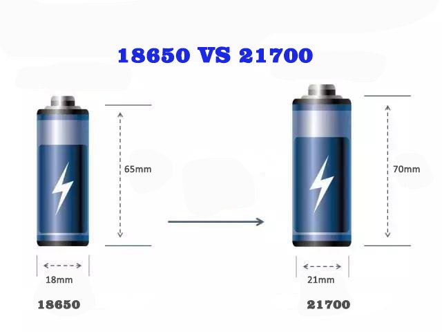
Seeing it I instantly thought, let’s write a nice article on how they differentiate and then thought how many battery standards are around? Asking Google again it came with 18650, 20700, 21700 and 26650 … and I’ve completely lost it, because there is a Wikipedia page on Battery sizes and it goes for pages.
So back to our story, I’ve decided to buy a pack of “21700 Lithium Batteries 4800mah Li-ion Industrial Flat Top x 4” batteries from a local supplier.
A pack of 4 batteries arrived next day so I went eagerly to meet with Richard to test it!
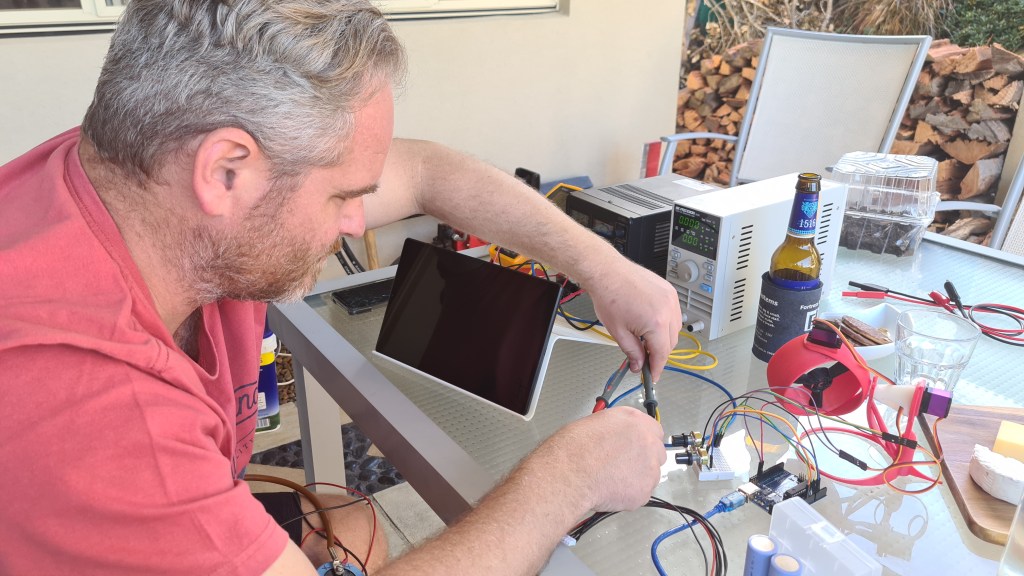
Risa kept torturing (continuous 1C discharge test) the battery for hours and came with quite significant difference to what they state to be! Batteries are sold as 4800mah, but Risa clearly found out that they are only 4000 mah.
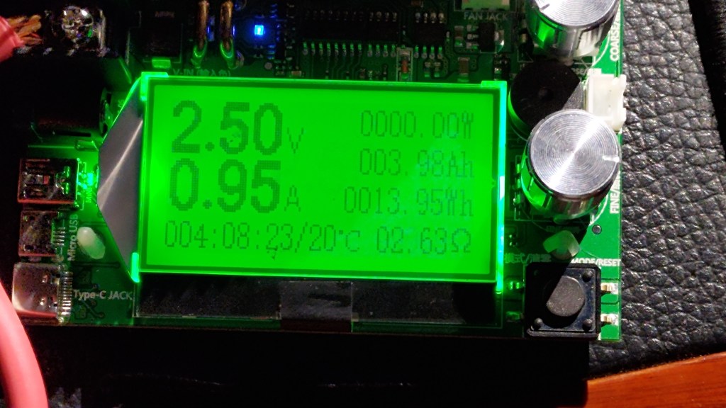
Even more test runs couldn’t come with undeniable fact that they are indeed 4000mah and not 4800mah.
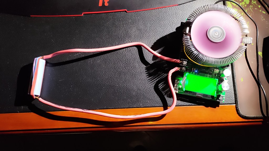
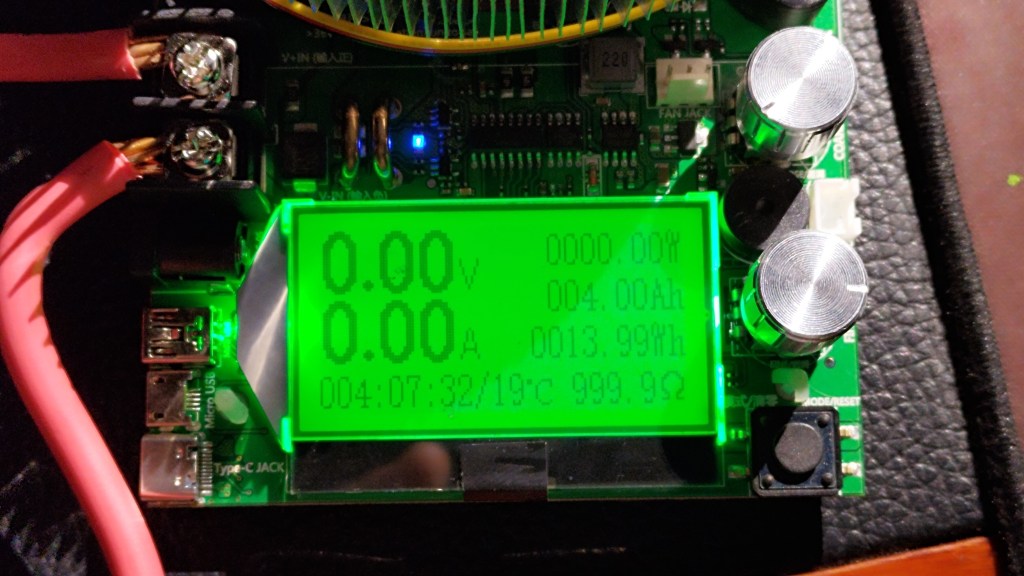


Crazy times – I’ll keep you updated.
So printing it is! Actually it all became a bit messy as I needed to do multiple iterations – practically on everything. That said – the code itself for this gimbal – spans over 560 lines and is becoming quite difficult to read.
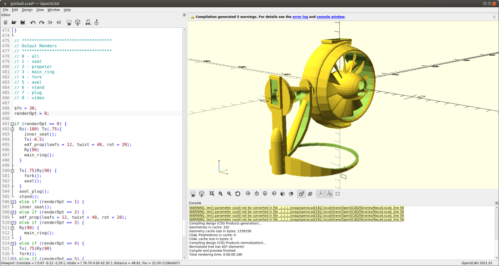
Let’s cover just its basics. Code comes with the rendering options like below, allowing me to work on each part separately and also render each individual part for STL export.
// ************************************
// Output Renders
// ************************************
// 0 - all
// 1 - seat
// 2 - propeler
// 3 - main_ring
// 4 - fork
// 5 - axle
// 6 - stand
// 7 - plug
// 8 - video
I’ve tried to have code self-describing where possible, but ran several times out of ideas on how to name the actual part. I think that module named chicken_leg_stand() says it all. Anyway, let’s go through some of those parts.
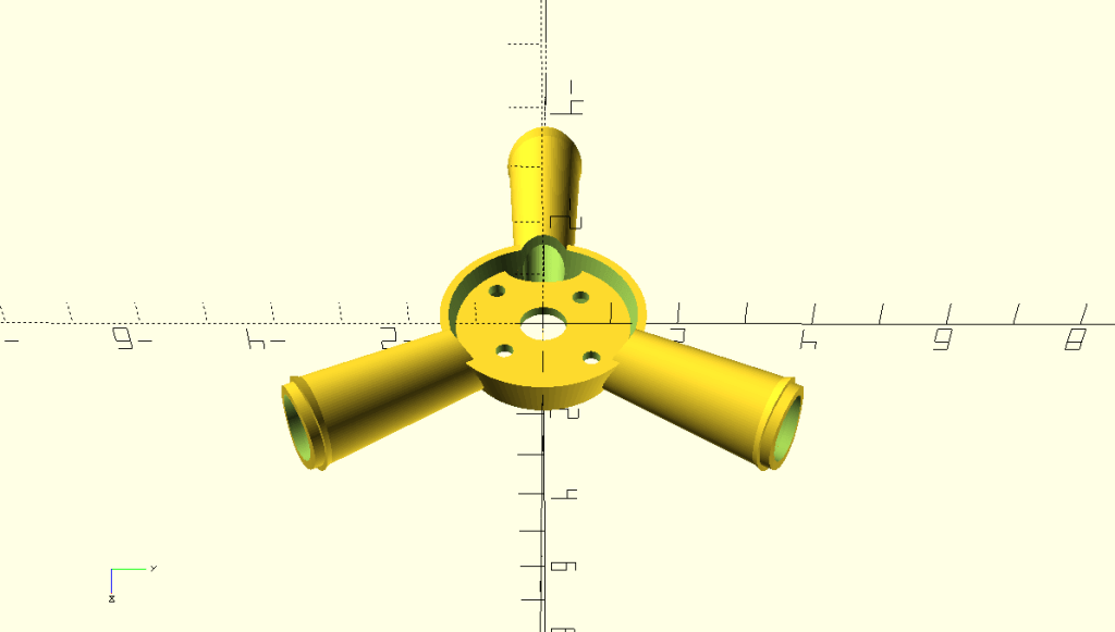

I’ve taken this from previous models and just adjusted to be as flat as possible + moved the “floor” bit up to fit smaller motor. Printing it with bed-level support works out reasonably well, but tubes look strange from below. Still, it does the job.
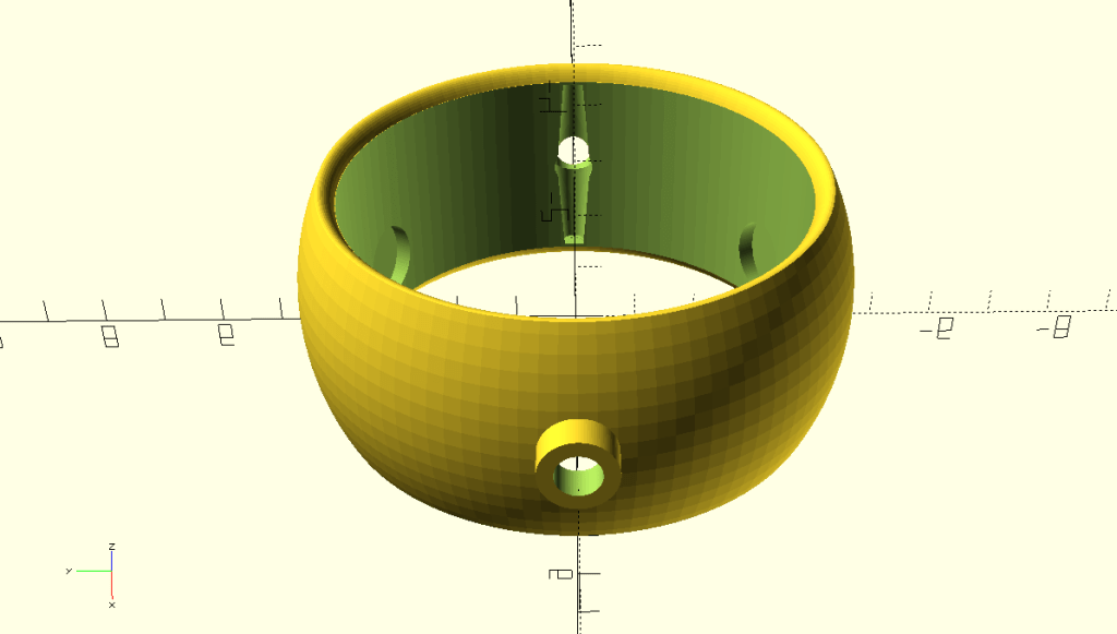

While it looks simple it took me a while to design all the holes to fit in the motor seat and even longer to fit in the servo lever (that black thing with a dot in a middle). Important thing here is that that servo lever has to be “submerged” in the ring material to the point where it is not interfering with the propeller and it holds strong enough to be able to twist whole that ring even when dealing with a spinning propeller.

Multiple challenges here. For needs to be precise size to allow good control of the ring , not smaller, not bigger – and allowing smooth 360 spin. Another problem was how to connect it to the axle – mainly without some super-complex trick. I’ve picked a simple cubic cutout + circle and squashed both a bit into a diamond-shape. Regarding the servo seat – I’ve reused the one we already had for a previous project.


The smaller the part gets – more time it takes to design it. This little monster was originally a part of the “fork”, but I somehow struggled to print it. Discussing this with Andrew he suggested separating it in two pieces – and it worked out. Except there was that new challenge to connect both pieces together.
Anyway – again a level shaft was needed, including an opening to install it. The master piece is in a circular-central maintenance shaft, allowing to use screw-driver to screw that lever in properly. I really like it.

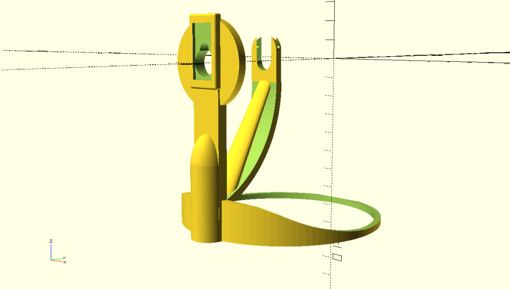

What to say here – I needed something where we can start testing and it will be at least semi-stable. Great inspiration here was Andrew’s display – so all that round bottom part – that’s it. I’ve been also facing a problem to anchor the axle properly and came with some sort of guillotine mechanism to do so. I suppose I could spend more time to make it nicer, but didn’t as it is intended for testing only.
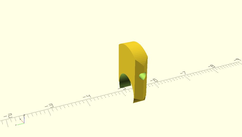
The last & smallest part – to fix the axle in the stand. It still takes 10 minutes to print this 1cm bit – incredible.
Now, if you’ve been brave enough to read it all the way, here is how Sebi hooked it all together with servos and his Arduino MEGA.

The best bit at the end – it really works! Enjoy!
To be able to strafe and also to put in life our fail-safe plan – we need to implement some sort of “drone” system. It will come with four gimbals distributed around the airship. To give you an idea on what I am thinking of check out James Cameron’s Avatar movie for this beast.

So I started putting together some design. Below are few pictures from a first draft.

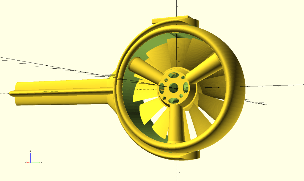
… and after a sort of week ending up with this.

Now when we know what we are looking for. We just need to print it and it.

Unfortunately my original plan ordering a 20Ah RC battery failed. Discussing things all around Richard / Andrew / Serge / Greg / Simon … and more, I actually decided to go with our own 6S battery for our project. Yes, I want it to look like the one on the picture below!

Andrew helped me to do some research. Obviously the first thing first – you need to pick proper battery cells for your project. The 18650batterystore shop/web provided reasonably good overview on this.
Also following set of videos is very insightful on what’s ahead of us.
So I started with shopping and surprisingly found a local (Brisbane) shop called Fubu which offers interesting batteries.
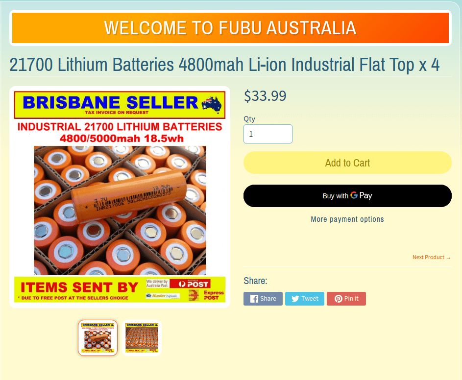
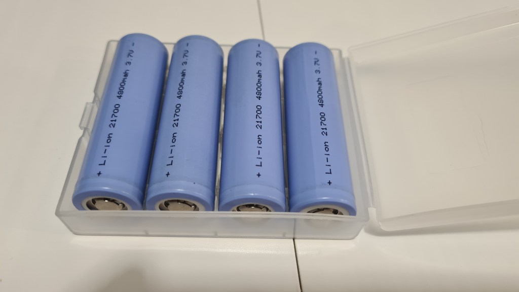
Next one was a pack of balancing cables. To my surprise – the best offer came from another Aussie shop in NSW.
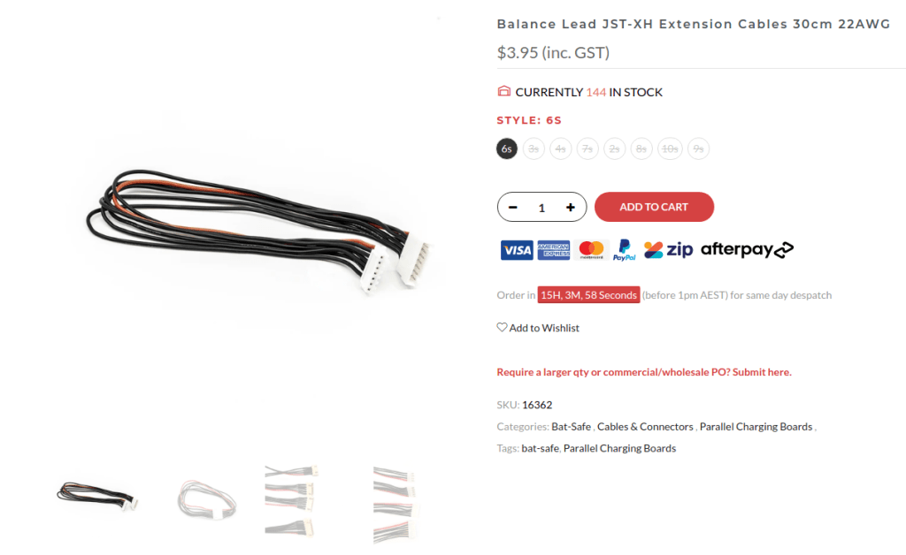
Final missing part is a “0.2mm thickness Pure Nickel Strip Nickel Tap Welding Tape 2P Spot Nickel”. Here it simply was eBay again, which helped me out, but it is very hard to say when it’s going to arrive.

Next on is to catch up with Richard and check what sort of batteries we’ve actually bought. 😀 But that’s for another day.
I’ve been thinking about all what can go wrong with this and came up with multiple areas of concern:
So we setup a tiny test with Sebi, when our jet is fully mounted and as you can see, it actually behaves beautifully and all seems stable.
As always, let us know what you think, all your ideas & comments are highly appreciated. 🙂
When randomly chatting with Andrew, he came with an interesting article called Acorn – the open source precision farming rover .

All that concept is pretty interesting, but the main question here is how they achieved such a navigation precision in the field?
This is being achieved through the differential GPS (DGPS) known as the base station, which is set up on a precisely known location.
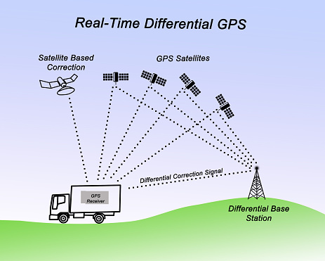
The base station receiver then calculates its position based on satellite signals and compares this location to the known location. The difference is applied to the GPS data recorded by the roving GPS receiver. Awesome concept, isn’t it?
I’ve ended up last time having those vector thruster prints in hand – missing the demonstration of how it works itself. Obviously I couldn’t wait to see it all working and next day had Sebi to activate that servo motor with his Arduino and he did! It was all awesome and we couldn’t get enough till I’ve got that idea to take a video so we have some evidence.
![Anti-Gravitatory Catoast [Comic]](https://i0.wp.com/www.geeksaresexy.net/wp-content/uploads/2014/04/cat.jpg?resize=600%2C448)
Pretty much following my favourite Finagle’s corollary to Murphy’s law “Anything that can go wrong, will—at the worst possible moment.” – when we tried to take that shot the servo axle started slipping as it shaved off the gear in the inner part of that vectoring thrust.
Seeing how unreliable it all is I came in with multiple enhancements which implemented the lever from that servo set to drive that steering. Result is on a picture below.

And instantly printed a new model and took a picture for comparison.
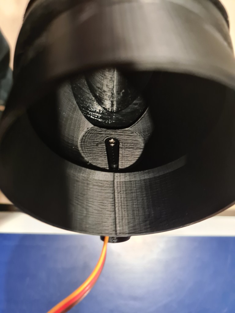
All clicked together instantly and whole system started feeling much more robust. So we did few “dry” runs and finally took that video together with Oli and Sebi.
It looks super-cool, don’t you think so?
I’ve been discussing our latest thrust vectoring ideas with Andrew & Josef and we’ve sort picked the “ball” shape exhaust and got some basic design.

Then I’ve kept working on it even more hours and this is how it looks now.

Main changes are that the funnel part is now outside the intake and also you can see a new platform for a servo which will be directly steering the funnel.
I took one more image while enabling transparency for that funnel so all that setup is more obvious.
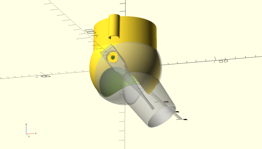
To get this, the code is not that crazy.
use <ShortCuts.scad>
use <edf_shared.scad>

//Sphere-based vector thrust exhaust
module axel_flexes_cutout() {
  T(6.3,40,5) Rx(90)
  minkowski() {
    cube([.1,11,5], center = true);
    cylinder(3,.3,.3);
  }
  T(-6.3,40,5) Rx(90)
  minkowski() {
    cube([.1,11,5], center = true);
    cylinder(3,.3,.3);
  }
  R(-90)Tz(40)
  difference(){
    cylinder(5, 6.7, 6.7, center = true);
    cylinder(5.1, 6, 6, center = true);
    T(0,-7,0)cube(15, center = true);
  }
}

module inner_part() {

  //cable holder
  difference() {
    Rx(-2)
    T(0, -39, 21)
    TubeSimple(25, 6, 6, 1);
    T(0, -30, 17)
    cube([12,10,61], center = true);
    T(0, -40, 48)
    cube([13,13,2], center = true);
  }

  //Tube
  Tz(17) {
    TubeSimple(3, 36.2, 34.5, 1.8);
    TubeSimple(30, 36.2, 36.2, 1.8);
  }
  difference() {
    union() {
      difference() {
        sphere(40);
        sphere(40 - 1.5);
        cylinder(40, 34.4, 34.4, center = false);
      }
    }

    //outlet cutout
    difference() {
      Tz(-42)
      scale([0.45,3,0.555])
      sphere(60);
    }

    //top axel cutout
    R(90)
    Tz(40)
    cylinder(5, 2.6, 2.6, center = true);

    axel_flexes_cutout();
  }

  //axels
  axel( 40, 6.1, 6, true); //upper axel
  axel(-40, 6.1, 6, false); //bottom axel
}

module outer_solid(dm, diff) {
  //main bowl
  sphere(dm);
  //exhoust
  Rx(180)Tz(5)
  scale([0.9,1.4,1])
  cylinder(65+diff/2, 27-diff/2, 20-diff/2, center = false);
}

module axel(tz, flexIn, flexOut, hole) {
  difference() {
    Rx(90)Tz(tz)
    cylinder(2, flexIn, flexOut, center = true);

    r = tz > 0 ? 8 : -8;
    tz2 = tz > 0 ? tz+7.8 : tz-7.8;

    if (hole) {
      //servo gear hole
      Rx(90)
      Tz(tz-1) {
        difference() {
          cylinder(9, 2.5, 2.5, center = true);
          n=12;
          for(w=[0:360/n:359])
          Rz(w)
          Tx(2.5)
          cylinder(9.2, 0.4, 0.4, center = true);
        }
      }
    }
  }
}

module servo_clamp() {
  //servo clamp
  difference() {
    intersection() {
      difference() {
        T(0, -36, -28)
        R(90,90,0)
        minkowski() {
          cube([75,13,21], center = true);
          cylinder(1, center=true);
        }

        //Main axel hole
        Rx(90)Tz(40)
        cylinder(20, 6.1, 6.1, center = true);

        //Side axel hole
        Rx(90)T(0, -6, 40)
        cylinder(20, 2.8, 2.8, center = true);

        T(0, -47, -5)
        cube([12,3,24], center = true);
      }

      //rudder
      R(-15.5,0,180)
      T(0,22,-12)
      scale([.13, .3, .7])
      sphere(100);
    }
    R(15.5,8,180)
    T(20,22,-30)
    scale([.13, .3, .7])
    sphere(100);

    R(15.5,-8,180)
    T(-20,22,-30)
    scale([.13, .3, .7])
    sphere(100);
  }
}

module outer_part() {
  //outer cylinder
  Rz(180)
  difference() {
    union() {
      outer_solid(41.5, 0);
      servo_clamp();
    }

    outer_solid(41.5 - 1.5, 2);
    T(0, 0, -120)
    cube(60, center = true);

    //inlet cutout
    Tz(45)
    scale([1.6,0.8,1])
    sphere(60);

    //Upper Axel cutout
    Rx(90)Tz(-39.5)
    cylinder(4.5, 2.8, 2.8, center = true);

    //axel holes
    Rx(90)Tz(40)
    cylinder(3, 6.2, 6.1, center = true);
    Rx(90)Tz(-40)
    cylinder(3, 6.1, 6.2, center = true);
  }
}

// ************************************
// Output Renders
// ************************************
// 1 - full
// 2 - inlet
// 3 - outlet
// 4 - video

$fn = 100;

renderOpt = 4;

if (renderOpt == 1) {
  outer_part();
  inner_part();
}

if (renderOpt == 2) {
  inner_part();
}
if (renderOpt == 3) {
  outer_part();
}

//Video settings
if (renderOpt == 4) {
  maxTwist = -36;
  rot = $t >= 0.5 ? $t*2 - 1 : 1 -$t*2;

  inner_part();
  R(0, 72*rot + maxTwist, 180)
  %outer_part();

  $vpt = [-4, -4, -13];
  $vpd = 450;
}
The next stage was to print it! It took roughly 4hrs to print each part. It was a quite a mesmerising experience to watch our 3D printer to keep tirelessly printing, so I took a video so you can enjoy a bit of it as well.
Our prints are now much better then before. Mainly I’ve slowed down printing speed to 75% and also increased the nozzle temperature to 250C. That seemed made layers to join together much better, making final print very stable.
And couple days later … voila!
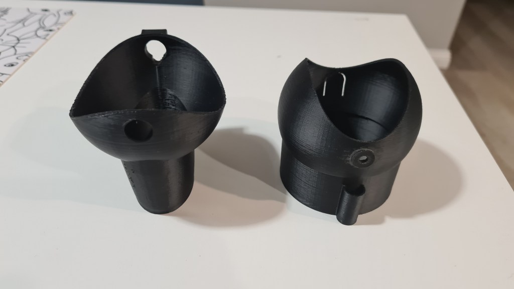
I’ve spent about an hour sanding few leftovers and making sure that servo fits in. Also I’ve used acetone to polish the main gimball and it ended up amazingly awesome!
I took many pictures, so just a selection of those in gallery below.

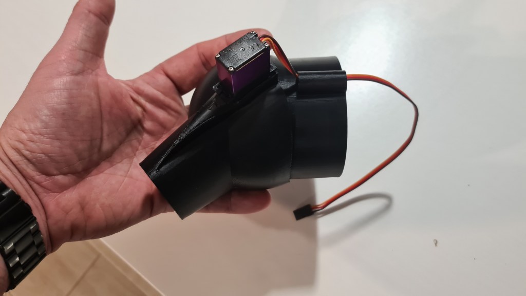
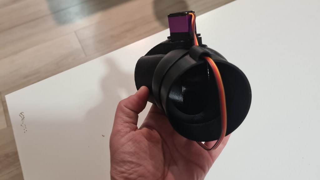

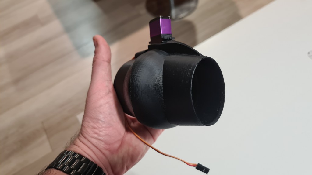

I also couldn’t wait and had to instantly mount it on our cart.
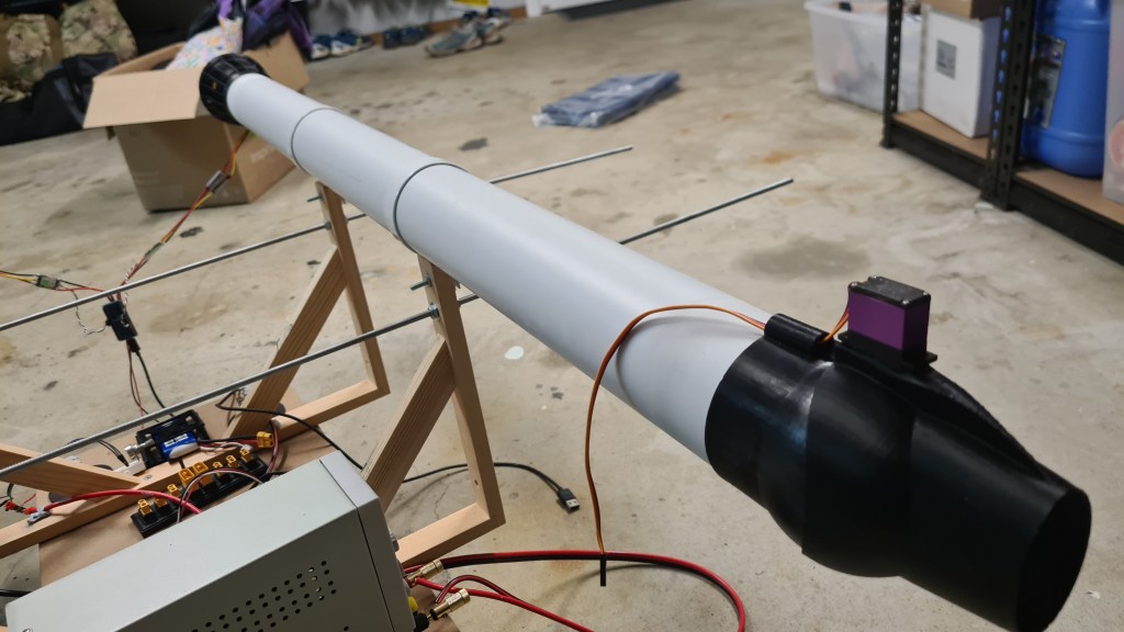
Last three pictures depict how I am seeing this working.
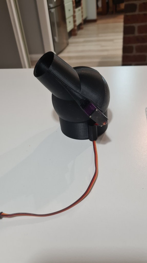


Last step remains – connect it to our BeagleBoneBlue to see it working. Well, I expect that would have to wait for another day. 🙂
Sebi came with another project on his own – using PS2’s (Microsoft PlayStation) Dual Shock 2 remote controller for initial cart steering. It took couple days for this idea to grow in a pretty long story – as always.
Let’s start from beginning – what is Dual Shock 2 remote controller?

Install Simple DirectMedia Layer library
$ sudo apt-get install libsdl2-dev
Save following text into test.cpp file:
#include <SDL2/SDL.h>

int main( int argc, char *argv[] ) {

SDL_ShowSimpleMessageBox( SDL_MESSAGEBOX_INFORMATION,
              "Hello World",
              "You have successfully compiled and linked an SDL2"
              " program, congratulations.", NULL );
  return 0;
}
Compile:
$ g++ test.cpp -o test -lSDL2
Run:
$ ./test

Set DS2 in a pairing mode with PS + SHARE buttons pressed at the same time.
Check available BlueTooth devices from BBB:
$ hcitool scan
Scanning ...
	38:68:A4:1D:00:7D	n/a
	A4:AE:11:3F:1D:F4	n/a <- this is our DS2
Try to read more details from our DS2:
$ sdptool records A4:AE:11:3F:1D:F4
Service Name: Wireless Controller
Service Description: Game Controller
Service Provider: Sony Interactive Entertainment
Service RecHandle: 0x10001
Service Class ID List:
  "Human Interface Device" (0x1124)
Protocol Descriptor List:
  "L2CAP" (0x0100)
    PSM: 17
  "HIDP" (0x0011)
Language Base Attr List:
  code_ISO639: 0x656e
  encoding:    0x6a
  base_offset: 0x100
Profile Descriptor List:
  "Human Interface Device" (0x1124)
    Version: 0x0100

Service RecHandle: 0x10002
Service Class ID List:
  "PnP Information" (0x1200)
Protocol Descriptor List:
  "L2CAP" (0x0100)
    PSM: 1
  "SDP" (0x0001)
Profile Descriptor List:
  "PnP Information" (0x1200)
    Version: 0x0103
Connect & trust & pair!
$ bluetoothctl
[bluetooth]# scan on
Discovery started
[CHG] Controller 50:8C:B1:5E:C7:66 Discovering: yes
[NEW] Device 88:C6:26:7A:6D:73 88-C6-26-7A-6D-73
[CHG] Device 88:C6:26:7A:6D:73 ManufacturerData Key: 0x0003
[CHG] Device 88:C6:26:7A:6D:73 ManufacturerData Value:
  00 60 3b 00 00 0b 18 54 cf e5 09 5a 88 c6 26 7a  .`;....T...Z..&z
  6d 73 12                                         ms.
[NEW] Device A4:AE:11:3F:1D:F4 Wireless Controller
[CHG] Device A4:AE:11:3F:1D:F4 Modalias: usb:v054Cp09CCd0100
[CHG] Device A4:AE:11:3F:1D:F4 UUIDs: 00001124-0000-1000-8000-00805f9b34fb
[CHG] Device A4:AE:11:3F:1D:F4 UUIDs: 00001200-0000-1000-8000-00805f9b34fb
[NEW] Device 38:68:A4:1D:00:7D [TV] Samsung Q70 Series (75)
[CHG] Device 88:C6:26:7A:6D:73 ManufacturerData Key: 0x0003
[CHG] Device 88:C6:26:7A:6D:73 ManufacturerData Value:
  00 60 3b 00 00 0b 18 54 cf e5 09 5a 88 c6 26 7a  .`;....T...Z..&z
  6d 73 12                                         ms.
[bluetooth]# trust A4:AE:11:3F:1D:F4
[CHG] Device A4:AE:11:3F:1D:F4 Trusted: yes
Changing A4:AE:11:3F:1D:F4 trust succeeded
[bluetooth]# pair A4:AE:11:3F:1D:F4
Attempting to pair with A4:AE:11:3F:1D:F4
[CHG] Device A4:AE:11:3F:1D:F4 Connected: yes
[CHG] Device A4:AE:11:3F:1D:F4 UUIDs: 00001124-0000-1000-8000-00805f9b34fb
[CHG] Device A4:AE:11:3F:1D:F4 UUIDs: 00001200-0000-1000-8000-00805f9b34fb
[CHG] Device A4:AE:11:3F:1D:F4 ServicesResolved: yes
[CHG] Device A4:AE:11:3F:1D:F4 Paired: yes
Pairing successful
[CHG] Device 88:C6:26:7A:6D:73 ManufacturerData Key: 0x0003
[CHG] Device 88:C6:26:7A:6D:73 ManufacturerData Value:
  00 60 3b 00 00 0b 18 54 cf e5 09 5a 12           .`;....T...Z.
Checking again & disconnect:
[Wireless Controller]# paired-devices
Device A4:AE:11:3F:1D:F4 Wireless Controller
[Wireless Controller]# disconnect A4:AE:11:3F:1D:F4
Attempting to disconnect from A4:AE:11:3F:1D:F4
[CHG] Device A4:AE:11:3F:1D:F4 ServicesResolved: no
Successful disconnected
[CHG] Device A4:AE:11:3F:1D:F4 Connected: no
And here we’ve hit a problem when SDL 1.2 sees that joystick and SDL 2.0 not. It all works on Ubuntu, but not on our BBB. It took me few days to figure out that it is a permission problem. Few sources here:
https://forums.libsdl.org/viewtopic.php?t=9772
https://github.com/libsdl-org/SDL/blob/e9af6dcd93e92013198ec7cc8445555632b86c37/README-linux.txt
http://wntrknit.freeshell.org/sdl2-joysticks/99-joystick.rules
I’ve ended up with following command which fixes the problem till another restart. Hopefully Andrew will be able to fix it permanently.
sudo chmod 0666 /dev/input/event*All working now! What you are seeing on a picture below are events collected from a DS2 controller connected over the Bluetooth to our BeagleBoneBlue!
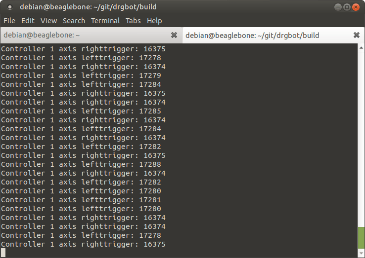
There’s been much more happening lately and we made some great progress. Sebi couldn’t wait to see things working so he hooked up both motors to a single Arduino, connected his PS2 remote controller and gave it couple test runs.

We had couple failed tests where it became obvious that:
I’ve been hoping that this will be our first try – but actually after employing Oli to carry the power supply (to make cart lighter), we’ve been able to deliver! Enjoy that proper sound of PS2-operated jet-cart! 🙂
Thinking about how we’ll feed all that monster I came with a plan. We have 2 main motors + 4 side ones and all of them are 4S (14.8V) – matching our battery pack. To get the best out of it we’ll setup everything in a parallel connection, getting 40000mAh on 14.8V ~> 592Wh.

Based on our previous tests, we’ll be draining 8.31A with each main motor, when running on max thrust with those. Bit of high-school maths gives us power consumption in Watts – 2*8.31A*14.8W -> 245W. So finally we get some first flight guess – 592 / 245 -> 2.29 ~> 2 hours and 15 minutes. Rounding down we are ending on safe-ish 2hrs operation time.
Not too good (my original plan was 4hrs), but not too bad as well. Next stage is to distribute that power to all engines. I’ve designed a simple bridge, putting those XT90s in a middle (battery power connector), surrounded by XT60 (motors). Main motors will go next to those XT90s and those copter-ones will go further away. Probably not the best design, but will have to do for now.
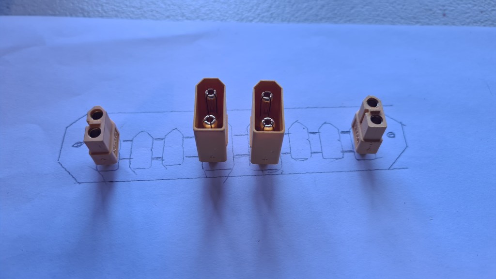
Now couple hours drawing in OpenSCAD came with following model. This is already a second version as the first one was precise too much and got destroyed when testing if it fits properly.
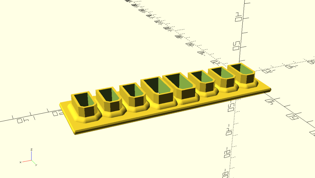
I still took several pictures as it actually looked super-cool.
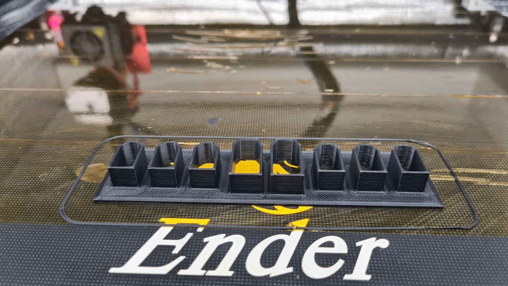


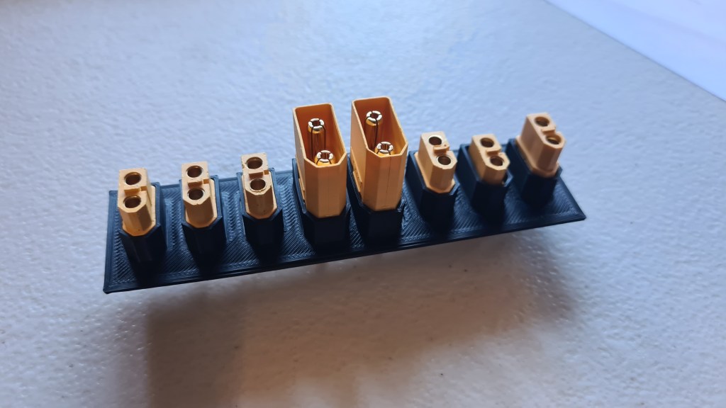
While waiting for a cover design and new print, Sebi soldered all connectors to a wire so those can be soldered further to the main plate. Well done Sebi!
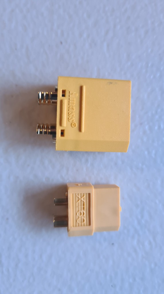
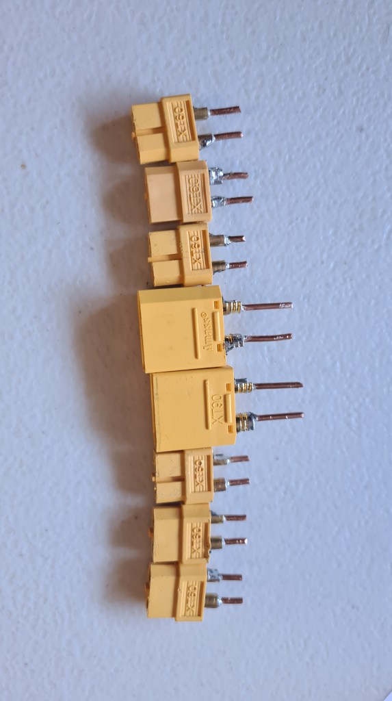
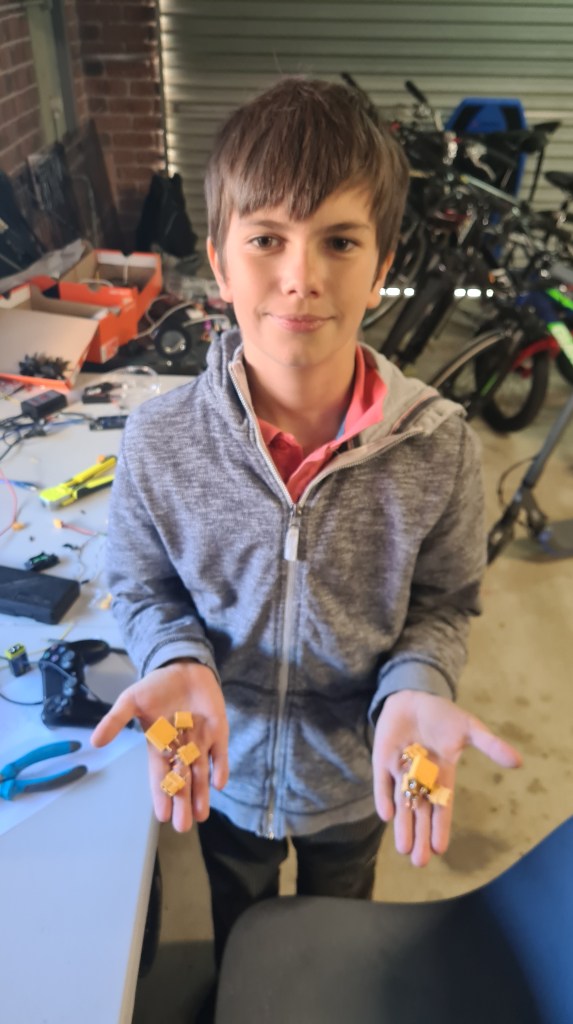

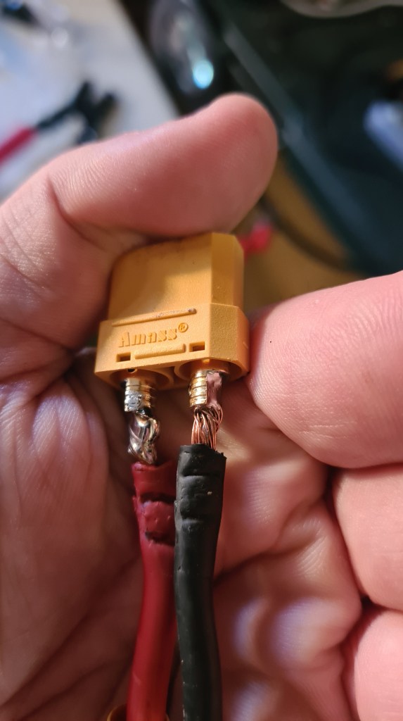

Finally put that all together and I think it looks super good! What do you think?


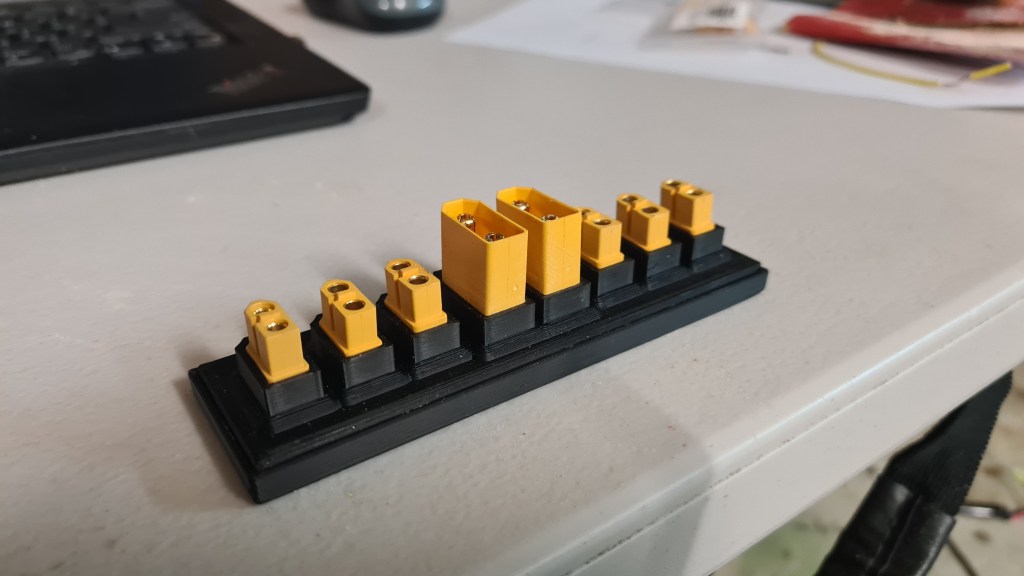
In regards of our Power-management preparations, I’ve asked our biggest sponsor (Veronika) if it would be possible to get a budget on some batteries – and I’ve got a green light! So, not to miss this opportunity, I did some quick calculations and came with “Turnigy High Capacity 20000mAh 4S 12C Lipo Pack w/XT90“.

Minimum Capacity: 20000mAh
Cell Count: 4 / 14.8V
Constant Discharge: 12C
Peak Discharge (10sec): 24C
Pack Weight: 1775g
Pack Size: 202 x 93 x 47mm
Charge Plug: JST-XH
Discharge Plug: XT90
… and we’ve got TWO on their way!
Thank you Veronika!!

Propellers are planned as an essential tool for powering our blimp propulsion. A good understanding of the science behind those will make a difference between making the project’s numbers black or red. Blimp’s cruising speed needs to be as efficient as possible, while they also need to be powerful enough to provide necessary lift off power for emergency situations.
So let’s ask the Wikipedia first. Wikipedia, what actually is a propeller?
A propeller is a device with a rotating hub and radiating blades that are set at a pitch to form a helical spiral, that, when rotated, performs an action which is similar to Archimedes’ screw. It transforms rotational power into linear thrust by acting upon a working fluid, such as water or air.
Wikipedia
Even Wright brother’s first air-plane had one!

Now, reading through all that Wiki, you’ll reach the part describing the propeller geometry characteristics:
… all that reads very educated and is for me quite difficult to see which value will have an impact on our performance and how much it actually matter as there is a too many variables I can’t predict. So I took it a bit step sideways and prepared a tiny science project. Let’s use our code from OpenScad and generate some random-ish propellers and test how they operate in our intended EDF scenario!
I took our already-existing propeller code:
module edf_prop(leafs, twist, rot){
  //Nose
  Tx(-2)
  Ry(90)
  difference() {
    Tx(0){
     scale([1,1,1.3])
     sphere(1.55);
     cylinder(h = 2, r1 = 1.55, r2 = 1.55, center = false);
    }

    Tz(0.5)
    cylinder(h = 2, r1 = 1.45, r2 = 1.45, center = false);

    Tz(-1.2)
    edf_lead_in_hole();

    scale([1,1,0.4])
    Tz(1.3)
    sphere(1.45);
    vent_holes();

    Tz(-0.2)
    cylinder(h = 0.3, r1 = 0.45, r2 = 0.45, center = false);
  }

  //Inner tube Wraps
  nw = 12;
  for(w=[0:360/nw:359])
  Rx(w) {
    T(-2,1.45,0)
    Ry(90)
    cylinder(h = 2, r1 = 0.07, r2 = 0.07, center = false);
  }

  *Tx(-0.1)
  Ry(90)
  TubeSimple(0.1, 1.5, 1.5, .1);

  //Propeller
  Tx(-1) {
  difference () {
    for(w=[0:360/leafs:359])
      Rx(w)
      proprep(tip_scale=1.48, L = 1.5, r = 4, twist = twist, rot = rot, naca = 1408);
      //delimiter
      Tx(-1)
      Ry(90) {
        TubeSimple(3, 4.4, 4.4, 0.6);
        cylinder(h = 2, r1 = 1.5, r2 = 1.45, center = false);
      }
    }
  }
}
And generated 14 scenarios:
T(0,-4,-4)
prop_to_print("1", "8/-30/-20", leafs = 8, twist = -30, rot = -20);
T(0,-4,-12)
prop_to_print("2", "12/-30/-20", leafs = 12, twist = -30, rot = -20);
T(0,-4,-20)
prop_to_print("3", "16/-30/-20", leafs = 16, twist = -30, rot = -20);
T(0,6,-4)
prop_to_print("4", "8/-40/-20", leafs = 8, twist = -40, rot = -20);
T(0,6,-12)
prop_to_print("5", "12/-40/-20", leafs = 12, twist = -40, rot = -20);
T(0,6,-20)
prop_to_print("6", "16/-40/-20", leafs = 16, twist = -40, rot = -20);
T(0,16,-4)
prop_to_print("7", "8/-50/-20", leafs = 8, twist = -50, rot = -20);
T(0,16,-12)
prop_to_print("8", "12/-50/-20", leafs = 12, twist = -50, rot = -20);
T(0,16,-20)
prop_to_print("9", "16/-50/-20", leafs = 16, twist = -50, rot = -20);
T(0,26,-4)
prop_to_print("10", "8/-60/-20", leafs = 8, twist = -60, rot = -20);
T(0,26,-12)
prop_to_print("11", "12/-60/-20", leafs = 12, twist = -60, rot = -20);
T(0,26,-20)
prop_to_print("12", "8/-50/-10", leafs = 8, twist = -50, rot = -10);
T(0,36,-4)
prop_to_print("13", "12/-50/-10", leafs = 12, twist = -50, rot = -10);
T(0,36,-12)
prop_to_print("14", "16/-50/-10", leafs = 16, twist = -50, rot = -10);
Code above generates 3D models like this:

Separated per picture, you can list through the gallery below. Each model has its ID, number of blades, blade angle and twist angle value.


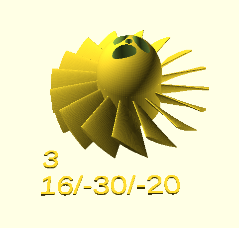


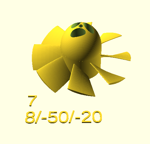
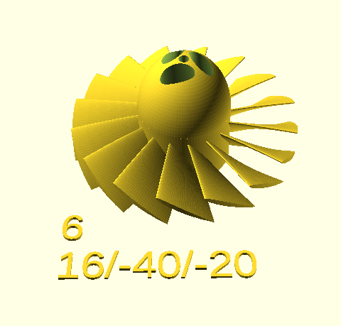


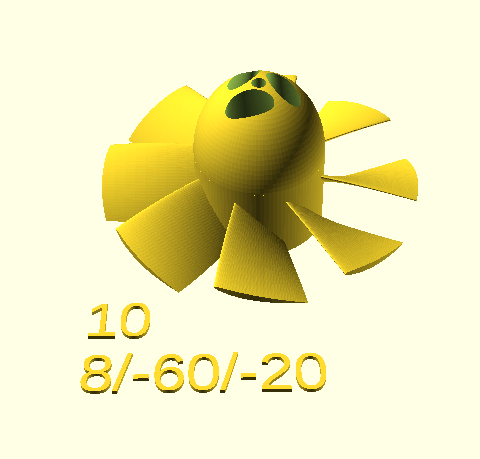


Rendering and transforming it into STL model and consequently into a 3D printer code (GCODE) took a while, while actual printing took … days, but result was worth it!

Next stage is to collect some data on how each propeller behaves. We’ve designed a see-saw test-bed.

I prepared following table for kids to have some fun.
| # | 10V/5A | 15V/5A | 17V/5A | 10V/10A | 15V/10A | 17V/10A | 17V/Max A |
| 1 | N/A | N/A | N/A | N/A | N/A | N/A | N/A |
| 2 | 1200 | 1650 | 1800 | N/A (4.40A max) | 2480 (8.8A max) | 3100 | 3070 |
| 3 | 1380 | 1600 | 1780 | N/A (6.33A max) | 2900 | 3100 | 3300 |
| 4 | 1360 (4.79A max) | 1720 | 1690 | 1360 (4.79A max) | 2300 (8.89A max) | 3300 | 3450 |
| 5 | 1300 (4.61A max) | 1700 | 1900 | 1300 (4.61A max) | 2700 (8.31A max) | 3300 | 3400 |
| 6 | 1150 (4.23A max) | 1550 | 1670 | 1150 (4.23A max) | 2250 (8.25 max) | 2710 (4.5A max) | 2710 (4.5A max) |
| 7 | 1200 (3.96A max) | 1900 | 2000 | 1200 (3.96A max) | 2480 (3.96A max) | 3050 (8.36A max) | 3050 |
| 8 | N/A | N/A | N/A | N/A | N/A | N/A | N/A |
| 9 | N/A | N/A | N/A | N/A | N/A | N/A | N/A |
| 10 | N/A | N/A | N/A | N/A | N/A | N/A | N/A |
| 11 | N/A | N/A | N/A | N/A | N/A | N/A | N/A |
| 12 | 1410 | 1730 | 1820 | 1420 (5.3A max) | 2920 (9.6A max) | 3240 | 3100 |
| 13 | 1400 | 1780 | 1890 | 1580 (5.8A max) | 3000 | 3380 | 3300 |
| 14 | 1370 | 1670 | 1800 | 1400 (5.1A max) | 2600 (9.22A max) | 2900 | 3000 |
| X1 | N/A | N/A | N/A | N/A | N/A | N/A | 2200 |
.. it sort of took weeks to get this done, but we’ve finished it! 🙂 As you can see there, prints 1,8,9,10,11 didn’t print properly, so they were not test. Still I think it all gave us some indication on what we are dealing with.
Having a fun, we’ve also added the X1 model – which is just a simple 2-blade propeller.

Putting it all in a graph – turbines 3,4,5 and 13 are clearly standing out.
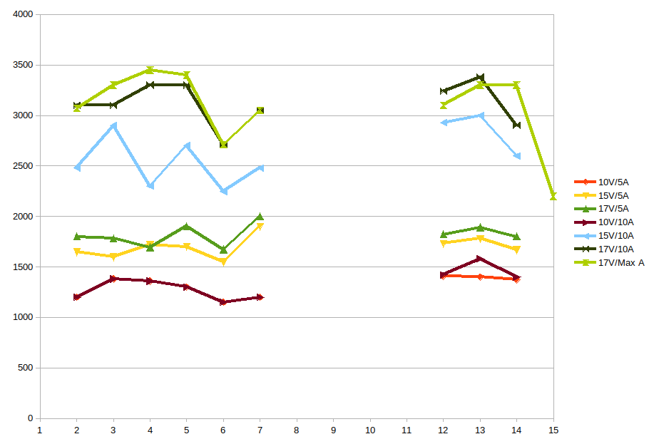
Long story short – our winner is number 4! 8 blades, 40′ blade twist and 20′ blade rotation.

Oh, and I almost forgot – we had a bit of fun while doing that as well. Sebi asked what would it be like to throw in a paper napkin … 😉
Seeing how our EDF duct design performs – I was all happy. The only thing here was that all that duct seemed to be structurally weak. Just holding that duct in a hand made it to change its shape enough to have the propeller start screeching.
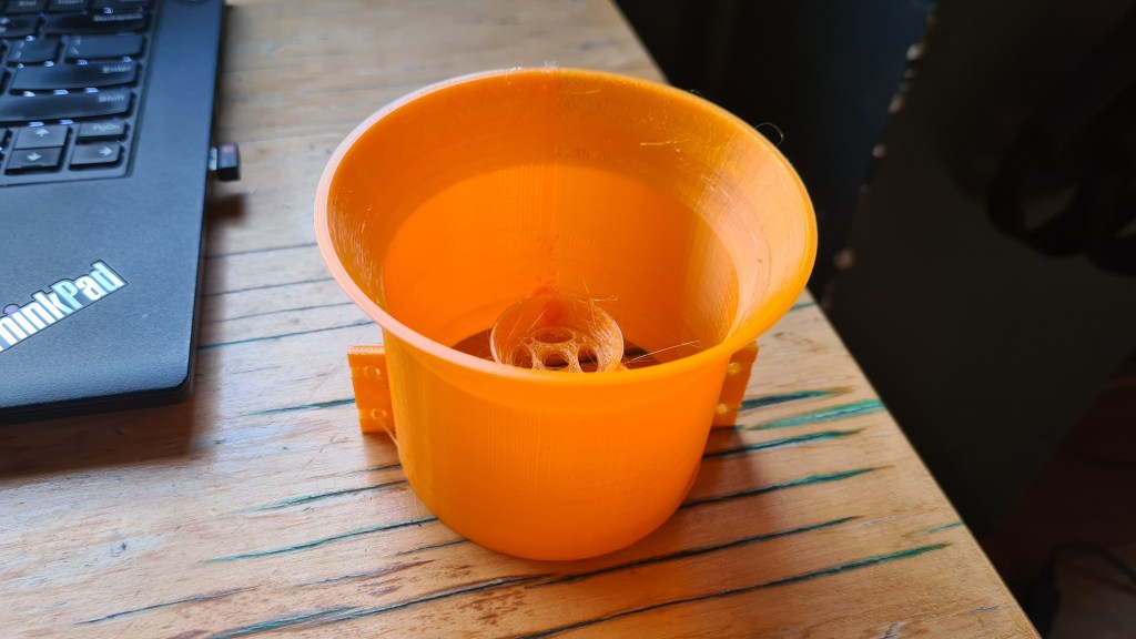
So i went to our original design….
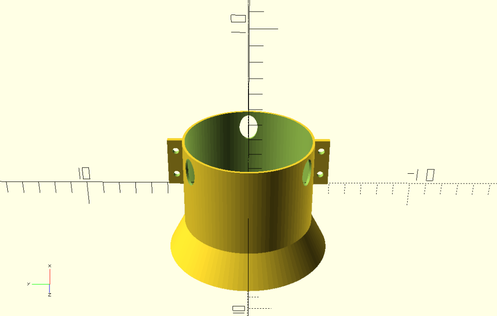
… and added the reinforcement mesh!

I think it looks awesome, but one more thing is missing – our EDF duct diameter is 80mm, but our tube’s outer diameter is just 70mm. So I added an adaptor..
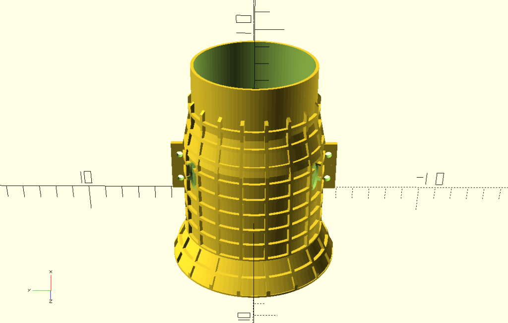
So we are moving to the second phase of this – handed our model over to the slicer – Cura Utimaker.

… and then to the printer itself. I took several pictures while it kept printing, as it took 12 hrs in a total.


It doesn’t look good on a picture, but with a closer look you’ll see that those are just additional supports not sticking properly to the model and keep messing around.
And then, when cleared of all spittle, here is a final model!
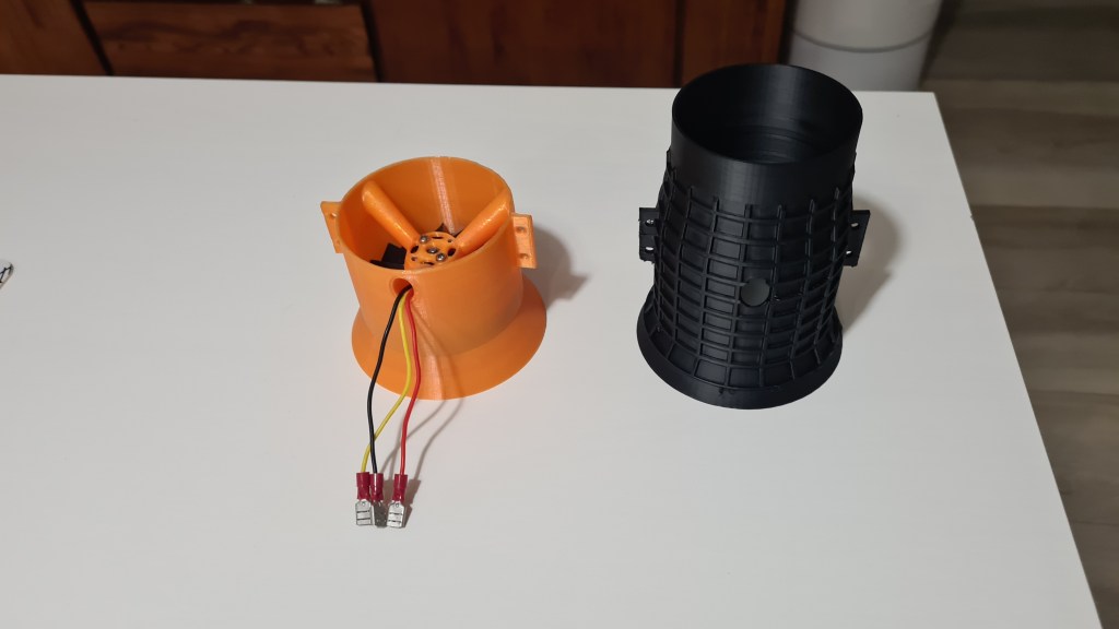
It actually looks awesome and feels even better! That tube reinforcement is making all that job it was designed for. I really like it. 🙂
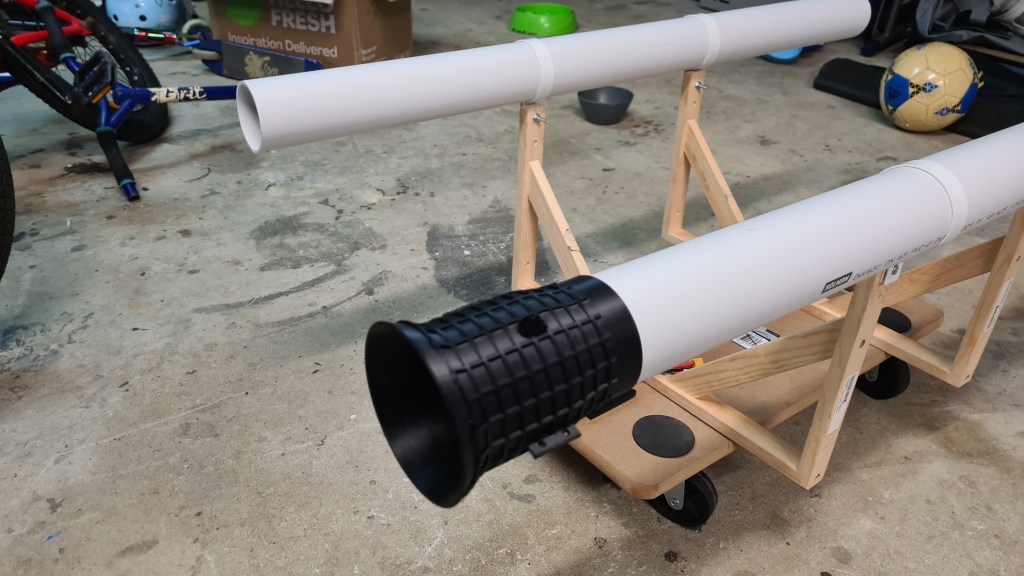
It needed few adjustments and we also need two of those. But that is a story for another day.
I did some shopping in preparation of our get cart project. First stop was local Bunnings store, which I visited with Serge – he helped me a lot to get plenty clever things.
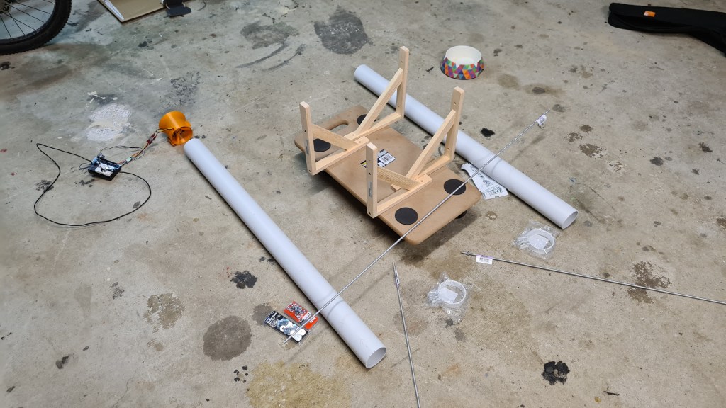
Anyway it took us few months to progress on this thing. I’ve collected few picture Sebi putting it together, but then seeing that there is nothing much to write about I am just providing a tiny gallery to see how all that worked out.


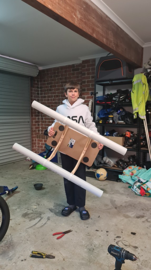
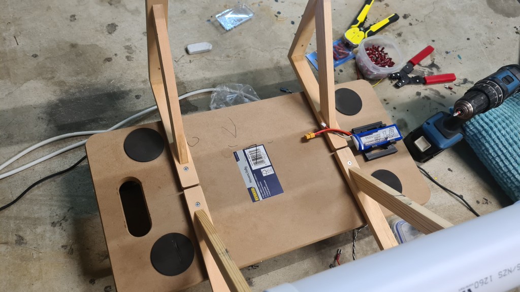
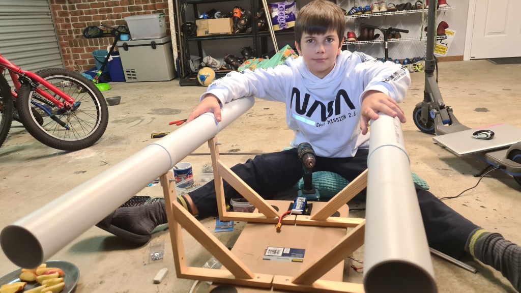

Sebi assembled all that on his own – I did nothing except giving some hints on having both tubes aligned. Well done Sebi!

Thinking how our BBB will operate remotely – I bought a “Turnigy 1800mAh 2S 20C Lipo Pack“.
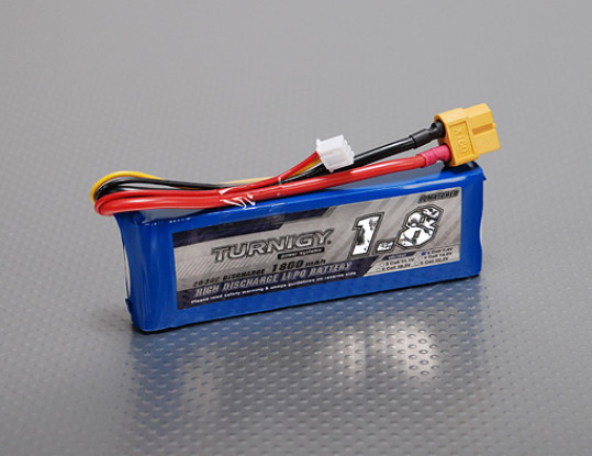
It arrived in a week time.

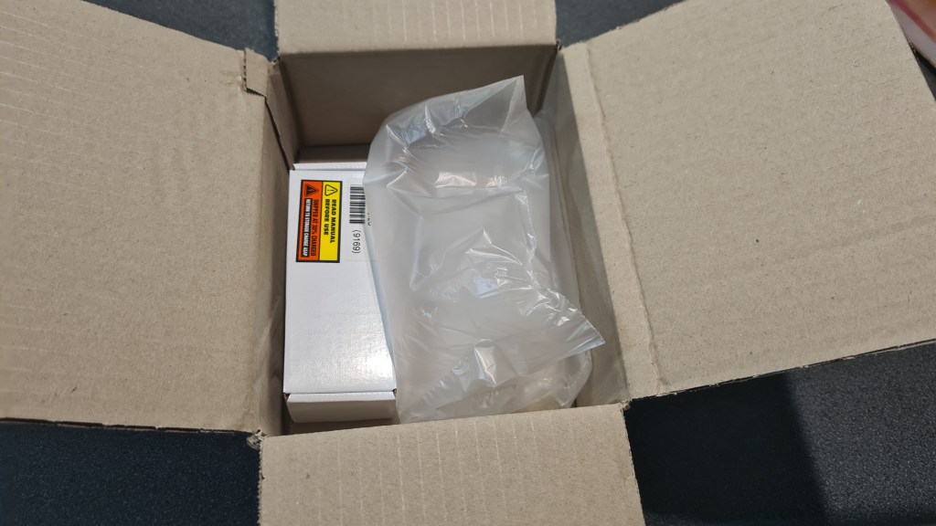

As per instructions – battery came 30% charged and … needed a proper charging! How lucky that Simon gave me few years back a LiPo battery charger – “iMAX B6AC 80W RC Battery Balance Charger”. Thank you Simon!

Attempting to solve the problem with traditional trial and error approach – to my surprise I unfortunately couldn’t find any of these charger connectors matching the battery one! Quick pop up to Jaycar solved it and I ended up with a pair of XT60 connectors.

Sebi soldered the female-one on nicely (red end).
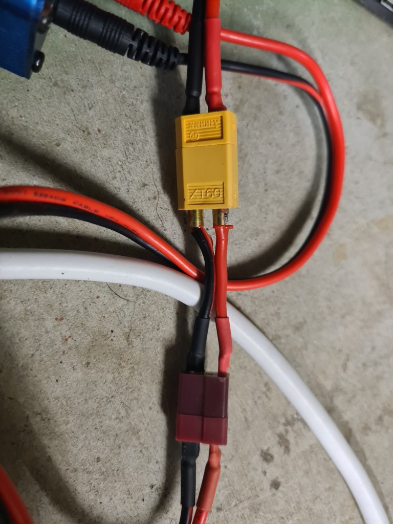
Next stage was connecting that all together – and wait!
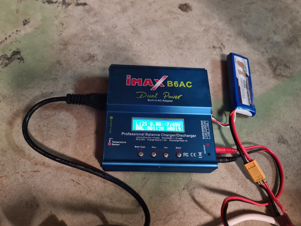
Initial voltage was 7.4V, while bit of googling revealed that we should see 8.4V when fully charged.

Waiting for a battery to get charged I did some reading and found an awesome blog about batteries – AmpOW. Particularly their page “Lipo Voltage Chart: Show the Relationship of Voltage and Capacity” – contains following table which I find super-handy for our project.

Also Sebi prepared another cable extension to actually connect to the BBB.

.. and our battery charging meanwhile finished. It took 92 minutes to feed it with 1189mAh.

Putting it together was than easy and the first test revealed that all is good! (See the blue LED shining.)
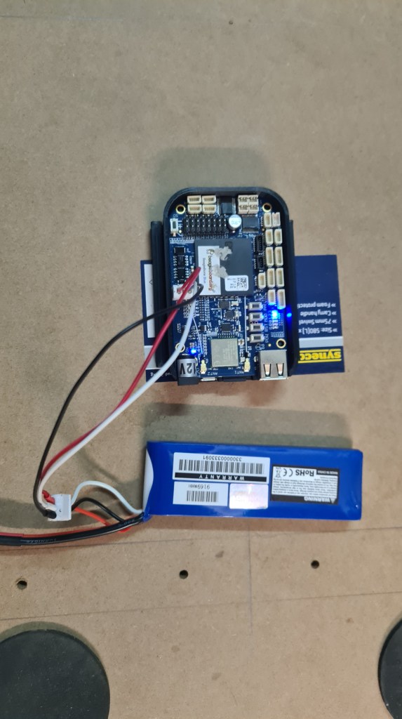
Eagerly we moved to the next stage and Sebi connected ESC + motor.

It took another 10 minutes of tinkering with BBB + checking the cable orientation to figure out proper testing command:
debian@beaglebone:~/git/librobotcontrol/examples/bin$ sudo ./rc_test_escs -c 8 -s 1
waking ESC up from idle for 3 seconds
done with wakeup period
<motor started here>
And it is a complete success for today!
There’s too much work in my (real) work so all things are unfortunately slowing down. Anyway, I’ve got finally couple minutes now where I’ve got to write an update. As there is too much to share, I’ve started with a bit title – Wiring jig story, however thinking about all what’s going on I think it will be more “Wiring jig report”.
This article is also a follow up on the “Heater for Carbon fibre tube manufacturing” article, so if you have no idea what’s going below – some relevant info might be there (e.g. If you are asking WHY???).
Long story short – after the latest disaster with tube diameter Vilda pretty promptly provided 60mm tube.

Huge thanks Vildo!
Now – from previous pictures, you surely noticed that wire spacing is ideal – causing the heat not being evenly distributed.

So I came with an idea of a simple “re-spacing jig” which I would screw through all that to get wire properly distributed along the tube. I’ve started with a simple “nut” design with a deep thread and it took me several prints to realise that that’s going to become serious rabbit-hole.
As the wire heated up, it partly glued with the Capton tape and my design + ABS Material strength wasn’t able to overcome that, always ending with that jig’s thread being ripped off or jig layers separation (collaps) … or both.
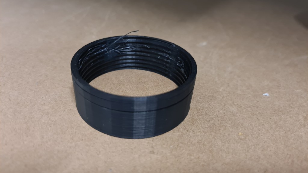
Based on my favourite Murphy’s law – If it jams, force it. If it breaks, it probably needed to be replaced anyway. – I started thinking about something else – a new plan!

Actually it worked out pretty simple, let’s unwind that wire first and rewire it properly. As getting that wire back on a spool manually would clearly take at least 30 minutes (it is 80m long), I decided to make a new jig which would allow to rotate that tube so I can use a drill. We’ll apparently need one jig to hold the tube somewhere-ish in a middle (1) and another point at the end (2). Oh, we can’t forget a completely new jig which will then allow re-wiring itself (3)!
Let’s fast forward several weeks to review where we are now.
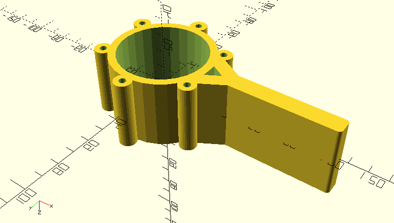
.. and printed + tested.

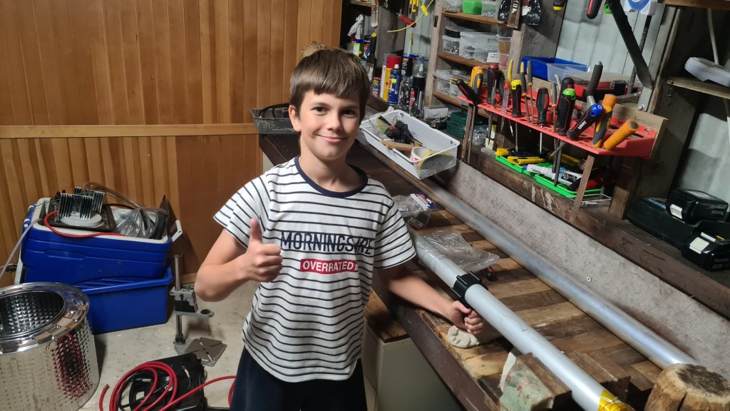


+ picture with reinforcing bolts mounted (the idea here is to prevent the layer separation)


Printing worked out nicely
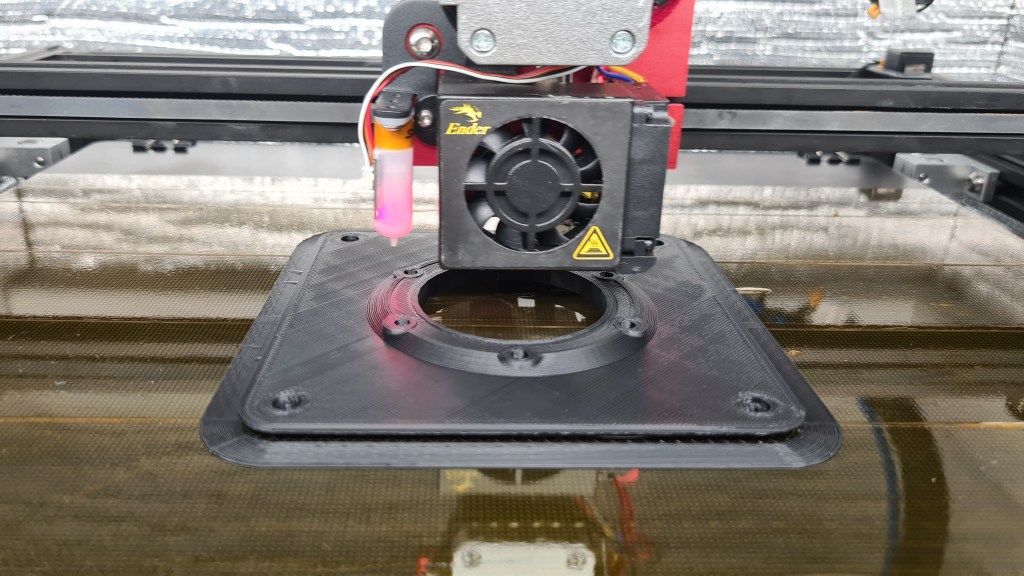
And the final product got printed …
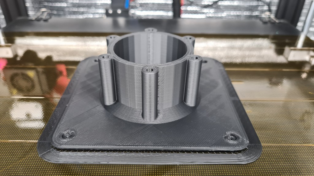


… wall-mounted and actually tested!
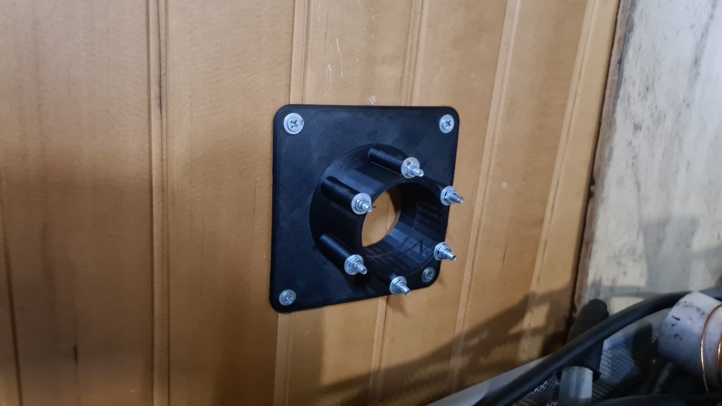


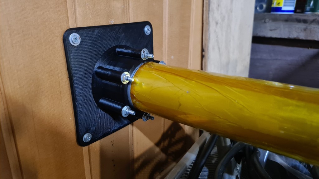
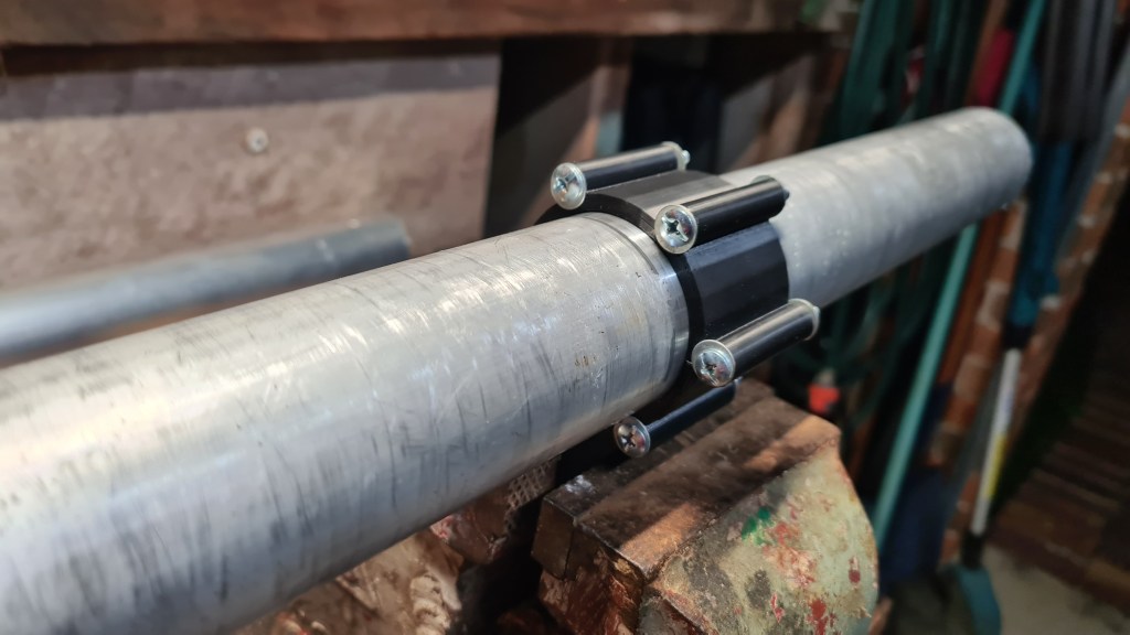
Final product – spool of a copper wire. Sort of where we’ve been 3 months back 😀

There is a spool holder and wire lead-in which enters the inner thread.
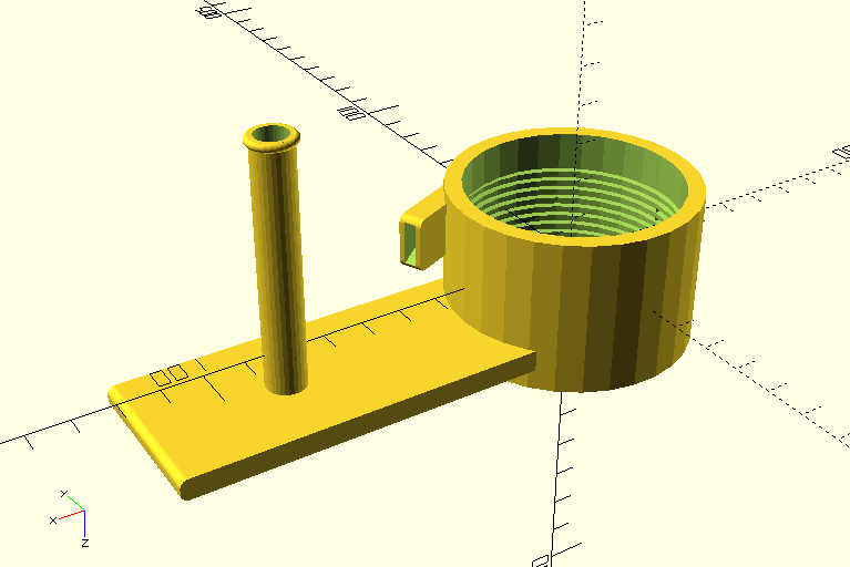
When having fun with the OpenSCAD I also did a picture showing all those weeks’ work at once.

Printed & tested.

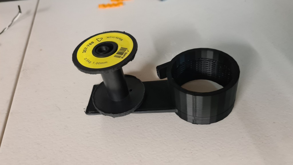
Where it quite stopped as the thread is not deep enough + the spool holder broke. So some re-designing is still needed here.
I think that this article is already super-long so I’ll end it up with a video of Sebi rewiring that tube.
That’s how the story ends for today – as always please leave us some feedback, it is greatly appreciated!
Sebi, on his own, came with a new 3D printer upgrade project – remote control. It all came like a surprise when he came and it was all set up and already working. Right now I am actually writing this to re-trace how he did it.
As the first, Sebi took one of his old Raspberry Pis – a tiny and affordable computer that you can use to learn programming through fun, practical projects.
Surprisingly there seems to be a picture showing how it works in practice:

Then he connected it straight to the printer like this:

Overall it looks pretty cool.

Right now it is possible to login (when on our home local network) to http://octopi.local/?#control and after login in with proper credentials you are presented with some awesome interface allowing full-control of our 3D printer!
Screenshot below shows a printer temperature settings and relevant graphs.

Now it is very easy to launch the print from a comfort of our sofa and check how it progressed without actual need to go to the garage at all!

I see myself becoming a seriously big-fat-blob soon. Luckily at least Oli has some new super-cool moves on his scooter which I can start learning meanwhile. 🙂
Well done Oli && excellent job Sebi! You are my stars!
To configurate the settings on theBLHeli_s you need a flashing tool, the one I used is the Arduino Mega 2560 and it seems to be the only one that works. You also need a computer and a cable to connect the flashing tool to your computer and two male to male wires.
Here are the steps you need to take to flash your esc:

Getting a hint from Serge – there has been “Hindenburg – The New Evidence” factual/documentary airing on SBS last night. Document came with a new footage of Hindenburg landing in Manchester Township, New Jersey, United States on May 6, 1937. Sort of 52 minutes of a nice recapitulation of all known evidence on this event plus few short shots on Hindenburg in flames.

Overall it came with quite a confident resolution that all disaster got caused by a static electricity discharge between Zeppelin’s envelope and its skeleton due to the envelop getting wet + skeleton getting grounded with wet ropes + a substantial hydrogen leak. Well, that sounds like a plausible explanation, while also not bringing anything too new.
What was, at least for me, much more interesting were some of general characteristics they went through. So with a little help from my favourite Wikipedia here they come:
Crew: 40 to 61
Capacity: 50–70[58] passengers
Length: 245 m (803 ft 10 in)
Diameter: 41.2 m (135 ft 1 in)
Volume: 200,000 m3 (7,062,000 cu ft)
Powerplant: 4 × Daimler-Benz DB 602 (LOF-6) V-16 diesel engines, 890 kW (1,200 hp) each
Maximum speed: 135 km/h (85 mph, 74 kn)
The really interesting part came where they were describing the comfort passengers had when being on-board. I did bit of Googling on this and found an excellent compilation of all that on the airships.net website. I hope they won’t mind that I’ll borrow some of their most interesting pictures & texts.
The passenger accommodation aboard Hindenburg was contained within the hull of the airship (unlike Graf Zeppelin, whose passenger space was located in the ship’s gondola).


Hindenburg’s “A Deck” contained the ship’s Dining Room, Lounge, Writing Room, Port and Starboard Promenades, and 25 double-berth inside cabins.
Airships.net

Picture below shows the dining room. Notice all being spacious and with an excellent view, plus all passenger areas on Hindenburg were apparently heated, using forced-air warmed by water from the cooling systems of the forward engines.

It all was beautiful and clearly wasn’t perceived as a cheap travelling option. A one-way ticket on the Zeppelin airship between Germany and the United States in 1937 cost $450 – the equivalent of $8,000 USD today. But that clearly had to be unforgettable experience. 🙂

I’ve told about our little project my Hungarian friend Zoli and provided him with the Blimp concept from Julia. Zoli then asked Ernő (apparently one of the best illustrators in Hungary) to give him a hand and they came with an awesome Blimp concept!

Loving it instantly, I replaced the Airlander image on our main page with this one. To make my post little bit interactive (and also as I never did it before and I am eager to try it), I am also adding a simple poll.
Have fun!
Finally, huge thanks Zoli & Ernő !!!

I have recently asked myself what sort of problems I am against when thinking of operating an airship in Queensland and kicked a bit of research on that topic.

After a few minutes of googling I’ve landed on website belonging to a CASA. The Civil Aviation Safety Authority (CASA) is a government body that regulates Australian aviation safety. CASA licenses pilots, registers aircrafts and oversees safety – this must be it!
Bit of browsing and following form materialised. I took a screenshot before pushing the send button to take some evidence.

It honestly took them a while to respond, but it was worth it!
On 2021-03-19 08:37:35+10:00 RPAS Mailbox wrote:
Hello Jan,Thank you for your email.
You will need to find an RePL training provider that is qualified to do the airship endorsement.
Please note that airships are divided by size of the envelope, not weight.
Find a training provider | Civil Aviation Safety Authority (casa.gov.au)
If not, you may have to get CASA to do your flight test.
Kind regards,
TimRPAS Administration
RPAS Branch
CASA \ Aviation Group
http://www.casa.gov.au
So I instantly discussed this with Mick and based on his advice I’ve prepared another email.
On 2021-03-19 09:40:16+10:00 Jan Bilek wrote:
Hi Tim,Thank you for your kind response.
I’ve been through some more documentation on CASA website namely:
https://www.casa.gov.au/drones/remote-pilot-licence
https://www.casa.gov.au/drones/rules/drone-safety-rulesI also discussed my findings with a professional helicopter pilot and it looks like that I potentially don’t need any license – if its usage intention is for sports and recreation only.
Would you be able to clarify on that please? FYI Intended envelope size is currently under 100m2.
Thanks again && Kind Regards,
Jan
Tim’s response was practically instant this time:
On 2021-03-19 13:28:47+10:00 RPAS Mailbox wrote:
Hello Jan,
I can confirm you do not have to have any licence to fly for sport or recreational purposes.
Kind regards,
TimRPAS Administration
RPAS Branch
CASA \ Aviation Group
http://www.casa.gov.au
Well, I suppose it is clear now! 🙂

Martin just sent me a link on this interesting video, which kind of resonates with me. 😉
I had a chat with Serge, consulting with him our progress in this space and he came with some interesting ideas. But let’s recap a bit first.
This is our cylindrical vector thrust exhaust Mk I.

Also after hearing Risa calling Hairdryer I spent few hours in OpenSCAD and replaced that central cylinder with a sphere.

I am adding that code here just for reference.
use <ShortCuts.scad>
use <Naca4.scad>

//Sphere-based vector thrust exhaust

module outer_solid(dm, size, diff) {
  cylinder(size+diff+10, dm-7, dm-7, center = false);
  sphere(dm);
}

module outer_part() {
  difference() {
    union() {
      difference() {
        outer_solid(40, 55, 0);
        outer_solid(38.5, 55, 2);
      }
    }

    //outlet cutout
    difference() {
      Tz(-39)
      scale([1,3,0.555])
      sphere(60);
      //axel clamp meat
      Rx(90)Tz(39.2)
      cylinder(4, 8, 8, center = true);
      //axel clamp meat
      Rx(90)Tz(-39.2)
      cylinder(4, 8, 8, center = true);
    }

    //axel holes
    Rx(90)Tz(39)
    cylinder(2, 6.2, 6.1, center = true);
    Rx(90)Tz(-39)
    cylinder(2, 6.1, 6.2, center = true);
  }
}

module inner_solid(dm, diff) {
  //main bowl
  sphere(dm);
  //exhoust
  Rx(180)Tz(5)
  scale([0.9,1.4,1])
  cylinder(65+diff/2, 27-diff/2, 20-diff/2, center = false);
}

module axel(tz, flexIn, flexOut, noSlide) {
  difference() {
    Rx(90)Tz(tz)
    cylinder(2, flexIn, flexOut, center = true);

    r = tz > 0 ? -8 : 8;
    tz2 = tz > 0 ? tz+7.8 : tz-7.8;

    if (noSlide) {
      //servo gear hole
      Rx(90)
      Tz(tz-1) {
        difference() {
          cylinder(9, 2.6, 2.6, center = true);
          n=12;
          for(w=[0:360/n:359])
          Rz(w)
          Tx(2.7)
          cylinder(9.2, 0.4, 0.4, center = true);
        }
      }
    } else {
      //slide
      T(0, -tz2, 0)
      Rx(r)
      cube(15, center = true);
    }
  }
}

module inner_part() {
  //inner cylinder
  Rz(180)
  difference() {
    inner_solid(38.2, 0);
    inner_solid(36.7, 2);
    T(0, 0, -120)
    cube(60, center = true);
    //inlet cutout
    Tz(31)
    scale([0.62,0.6,1])
    sphere(60);

    //Upper Axel cutout
    Rx(90)Tz(-39.5)
    cylinder(4.5, 2.8, 2.8, center = true);
  }

  //axels
  axel( 38.3, 6.1, 6, true); //upper axel
  axel(-38.3, 6.1, 6, false); //bottom axel
}
I did a print in 1:2 not to loose too much of material and it worked out pretty well again.
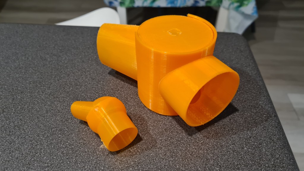
However, Serge came with an idea that having a cone exhaust like this – forming a jet – might cost us too much on overall efficiency. So I’ve designed something else!
use <ShortCuts.scad>
use <Naca4.scad>

//Rudder-based vector thrust exhaust
module servo_gear_hole(dm) {
  T(dm-1,0,dm)Ry(90) {
    T(0,0,-4)
    cylinder(6, 1, 5, center = true);
    difference() {
      cylinder(4, 10, 10, center = true);
      //servo gear hole
      Tz(-1) {
        difference() {
          cylinder(9, 2.5, 2.5, center = true);
          n=12;
          for(w=[0:360/n:359])
          Rz(w)
          Tx(2.5)
          cylinder(9.2, 0.4, 0.4, center = true);
        }
      }
    }
  }
}

module bottom_axel_hole(dm) {
  T(-dm+1,0,dm)Ry(270) {
    T(0,0,-4)
    cylinder(6, 1, 5, center = true);
    cylinder(2, 10, 10, center = true);
  }
}

module cone(dm, height, diff) {
  //left tube
  T(0,60,-height)Rx(31)
  cylinder(height+18+diff, dm-diff, dm-diff, center = false);

  //right tube
  T(0,-60,-height)Rx(-31)
  cylinder(height+18+diff, dm-diff, dm-diff, center = false);

  //central part
  Tz(-60)
  scale([dm*2-diff*7,1.5,1.5])
  R(0,270,0)
  circle(dm+diff/2,$fn=3);
}

module body(dm, wall) {
  height = 100;
  Tz(height/2)
  intersection() {
    difference() {
      union() {
        Tz(height/2-25)
        cylinder(height/2+20, dm, dm, center = true);
        cone(dm, height, 0);
      }
      cylinder(height+wall+20, dm-wall, dm-wall, center = true);
      cone(dm, height, wall);
    }
    //nice conic trim
    scale([2,2,2])
    sphere(dm);
  }
}

module rudder(dm, wall) {
  $fn=50;
  //main plange
  Tz(dm)
  R(0,90,90)
  minkowski() {
    cube([30,1,1]);
    cylinder(r=dm-wall*1.5, h=2, center=true);
  }

  //reinforcement 1
  Ry(90)T(-dm,0,dm/3)
  scale([5,1,1])
  cylinder(2, 7, 7, center = true);

  //reinforcement 2
  Ry(90)T(-dm,0,-dm/3)
  scale([5,1,1])
  cylinder(2, 7, 7, center = true);
}

$fn = 100;

dm = 42;
wall = 1.5;
body(dm, wall);
servo_gear_hole(dm);
bottom_axel_hole(dm);
rudder(dm, wall);
What OpenSCAD translates into this beauty:
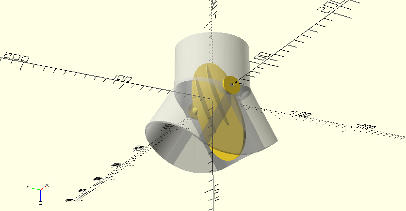
And then I set it to move 😉
… and now we are ready to do some new printing! 🙂
Printing those propellers was a great success, but looking at those I could see space for improvement – those printing layers seem to be too obvious. Without any understanding if there is a real impact on a performance whatsoever I did some reading on this topic and except the obvious – sanding, there was a picture of using Acetone on ABS filament with very good result. So I bought Acetone!

Took a close picture of one of our propellers “before”:

Then I took one of kids brushes and applied it:
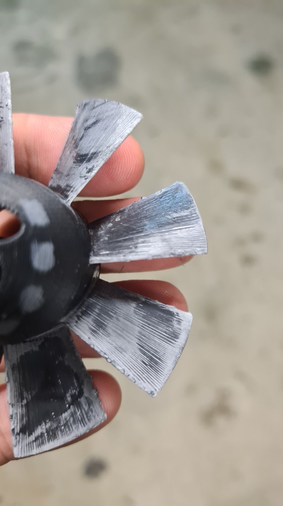
Well, that white colour – that came from that brush, so it doesn’t look well. On other hand there was quite a significant improvement in the surface smoothness!
I took one more picture, which is still not perfect, but already shows a bit of that “glassy” effect there.

Except that white part – I am happy and plan to apply this procedure on all propellers (which a clean brush).
Risa and Martin came to help me to put it all together, but very first thanks belong to Vilem to source another 5cm pipe! Another 5cm pipe? What for? Well I’ve messed it up. I thought I am ordering the 6cm one, but it came up as the 5cm.

That 6cm pipe is intended to be the upper layer, so it is not a big deal for this time, we can still continue. Risa also prepared a thermal control circuit. Even we haven’t used it today it is ready to go.
Now let’s kick off. First problem was to provide some sort of automated way to do that wire winding. Risa and I have been discussing possible options, while Martin took Oli’s Nunchaks and quickly fitted one of its sides into to tube with almost artistic usage of some carpet-tape.
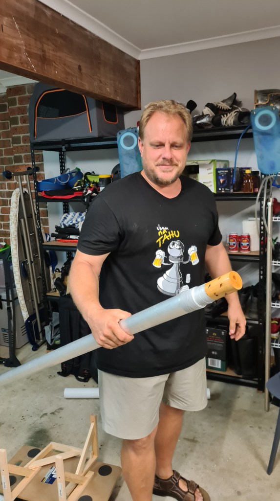
In the similar manner Martin put together a tube holder so it can rotate freely and used my cart to allow stable movement alongside the tube when winding the wire.
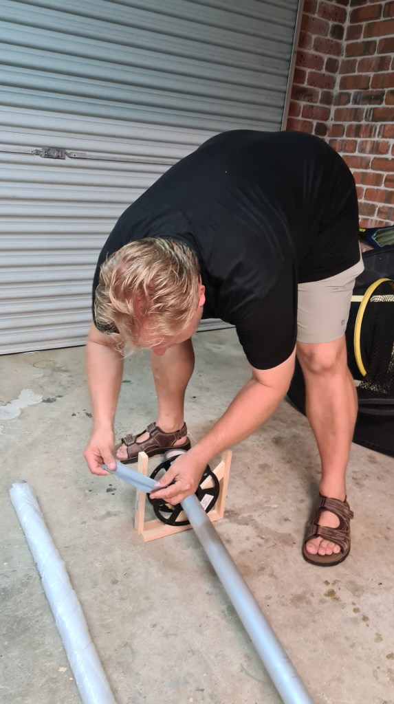


I took number of videos of Risa operating rotations and Martin actually doing the job. It was almost fascinating to watch all that happening.
In the next stage we’ve applied the Kapton tape to ensure that the wire winding won’t short-circuit through the tube. Risa came with a clever idea to use it long-way, instead of winding it, which instantly shown being very efficient.

Kapton-tape insulation looked awesome.

At this stage team was working on 101% and all team members practically having a gold-fever symptoms seeing it getting delivered.

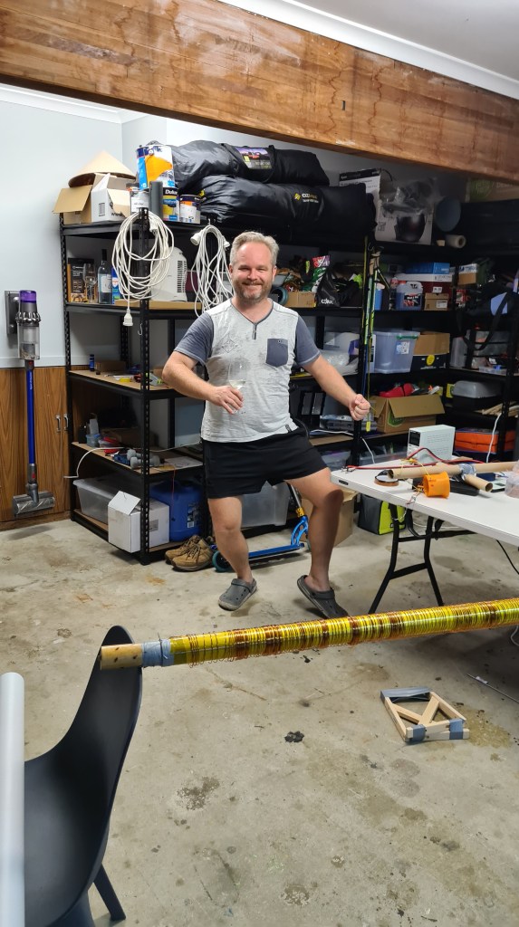
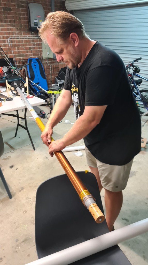
Yes – that’s Risa dancing traditional Kosik’s Maori war-dance on the picture above – this completely crazy atmosphere it was!
Anyway, winding done, we’ve moved to the shed to connect it with a welder and check if Risa’s calculations were right.
On the picture above you can see the welder being connected and running 48V on 28A through our heater. Risa brought a thermal camera so a gallery with pictures showing how it was all heating up follows.

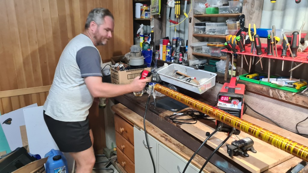
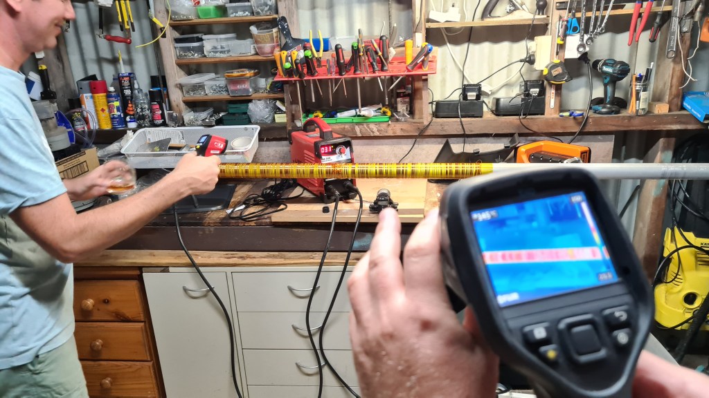


Problem with that thermal camera was that it was sensitive up to some 150C, while our hand-held IF thermometer started measuring temperatures over 240C. In the final stage I’ve asked Barca to stand as a model to demonstrate how it all works – live.
And that was it! We’ve achieved a lot this time. Heater is heating, all looks pretty stable. I’ve prepared a tiny TODO list for a next stage:
.. but mainly ask Vilda to get me one 60mm aluminium tube!!

Thanks again to Risa, Martin and also Vilda for a huge support, it was fun and I really enjoyed this session with you!

This is a bit of spin-off on Risa’s thermal controller. Below you can see the “battle plan”. The idea is that this device will be connected to a thermal probe and Arduino UNO and based on the code it will regulate current going to the heater.

And this is a final product – all made by Risa (c).
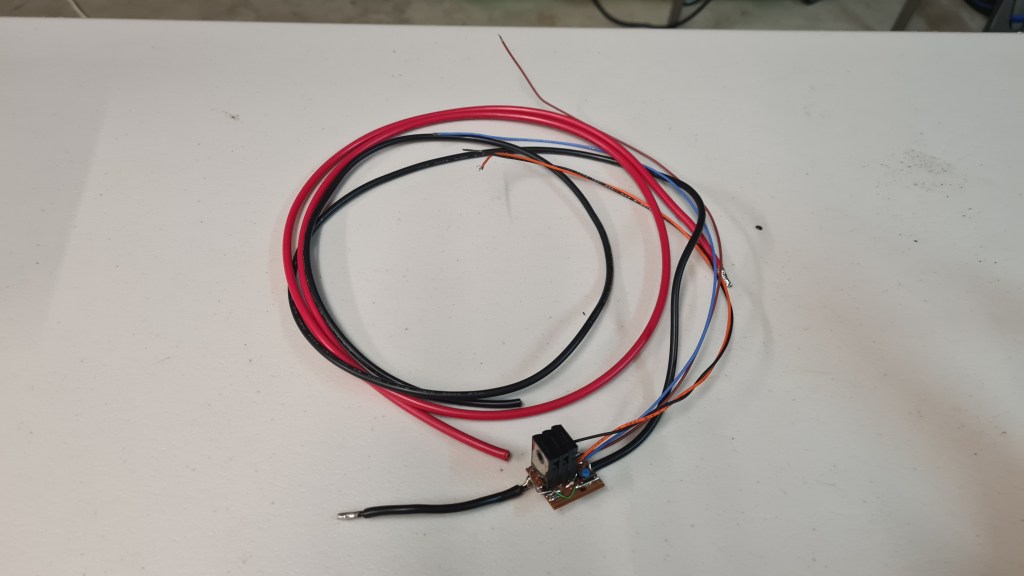
And bit closer you can see Risa’s Mosfets in a series:
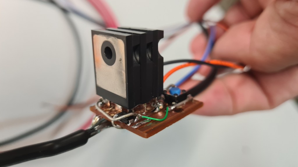
Can’t wait to see it in action 🙂
This must be the longest title so far! 🙂 Anyway, while I can’t figure out how to shorten it, the idea is to acquire and test a manufacturing technology to source carbon fiber tubes for our project internally.

I’ve discussed it with Richard(s) and Serge a lot and plan is like this, we’ll build a heater tube which we can wrap up with a carbon fiber tape + resin, heat it up and wait for it to cure. When done we’ll move the sleeve and repeat the procedure for another part.
Device needs to heat up our Carbon fiber wrap up to 170C and keep it there for almost 2hrs! Carbon fiber curing diagram follows – sourced from here.
So we need to build that heater first! Richard sent me couple videos links inspiration:
And also this one:
Richard also did all calculations and evaluations needed. As the idea works with our welder inverter sourcing the power, main parameters needed to be checked.

Then Richard did Excel to find out our wire length and diameter:


Out of those you can see that we are aiming to use 1mm 80m long wire on a Kapton Tape-wrapped tube to provide the cable insulation and also assist the heat spreading.
Shopping:
1/ Insulated copper wire 18awg 80m
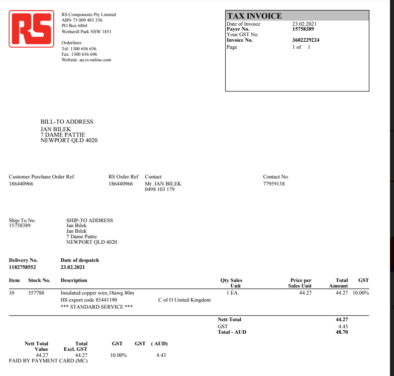
Checking on the wire specifications it sort of mentioned that its parameters are guaranteed up to +155C (insulation layer), what made me little worried as we plan to operate around 170C and possibly even more.
The wire itself shouldn’t be a problem, but that is where the Kapton tape comes in!

2/ Kapton tape (https://www.ebay.com/vod/FetchOrderDetails?itemid=222520763363&transid=2524283657012&qu=1&ul_noapp=true)

Kapton will well insulate wire from the aluminium tube and it can sustain temperatures up to 350. That should be well enough to have us covered.

3/ 2m long aluminium tube (huge thanks to Vilem for finding it and donating it to our project) 5 cm in diameter
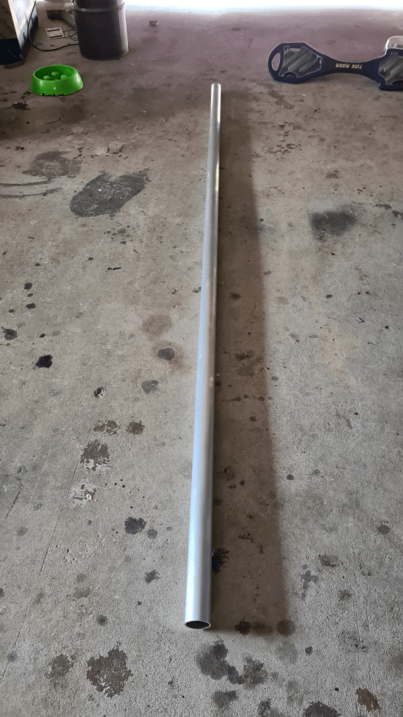
Actually whole list with the tubes offering comes here:

The wire arrived practically the next day, it looks actually much smaller than what you would imagine under “80m long copper wire”.

Kapton tape arrived shortly after, but I realised that it is 2cm wide too late. So instantly ordered two more 5cm wide. Those arrived week later.

All seems to be ready! Let’s call in whole team … in a next post.
Hi team, I had a chat with Sebi on our needs and we are getting into a situation where we would like to get some support in going forward. We are in an acute need for 3D printing filament. The idea is to offer some of our printing services to raising a few dollars allowing us to stock up on filament.
To be 100% transparent all donors will be listed here with their donations, where their names will be anonymized if required. 100% of the fundraiser will go into buying the 3D filament which will be used mainly for the Blimp project. I am reserving the right to change the money purpose in case the donors will go crazy, as filling our garage with 3D filament wouldn’t help our cause. Still, all spendings will be listed here.
The current goal is to raise $155.4 AUD which will go straight to the following filaments from Inkstation.

Here’s how I imagine that going to work. There are donation levels, that we’ve prepared with Sebi, which will gradually reward each donor with a more valuable prize.
| Donation goal | Reward |
| $5.00 | 3D blimp model |
| $10.00 | 3D blimp model + donors name on the blimp |
| $15.00 | All above + you get a choose a colour (from available filaments) |
| $50.00 | Original Blimp T-Shirt (Julia design) |


Thank you for your gift in advance!
| Date | Donor | Donation | Message |
| Sum | $0 |
I’ve been playing with this idea for couple months – let’s design my own thrust vectoring nozzle! As always, Wikipedia provided some initial thoughts.

module outer_solid(dm, size, diff) {
  cylinder(size+diff+10, dm-7, dm-7, center = false);
  Ty(dm+2)
  Rx(90)
  cylinder(dm*2+diff+4, dm, dm, center = false);
}

module rim(r = 1) {
  rotate_extrude(convexity = 10)
  translate([38.5, 0, 0])
  circle(r);
}

module outer_part() {
  difference() {
    union() {
      difference() {
        outer_solid(40, 55, 0);
        outer_solid(38.5, 55, 2);
      }
      Ty(-41)Rx(90)
      rim();
    }
    T(-55, -43, -45)
    Ry(45)
    cube(81.5, center = false);

    //outlet cutout
    Tz(-39)
    scale([1,0.66,0.555])
    sphere(60);
  }
}

module inner_solid(dm, diff) {
  //cylinder
  Ty(dm+2)
  Rx(90)
  cylinder(dm*2+diff+3.5, dm, dm, center = false);
  //exhoust
  Rx(180)
  Tz(26)
  scale([0.9,1.4,1])
  cylinder(65+diff/2, 27-diff/2, 20-diff/2, center = false);
}

module lever() {
  Ty(-44)Rx(90){
    difference() {
      union() {
        //core
        cylinder(10, 7, 7, center = true);
        //lever
        Tz(6)
        scale([5,1,1])
        cylinder(2, 7, 7, center = true);
      }
      //bolt holes
      T(30,0,5.5)
      cylinder(4, 2, 2, center = true);
      T(-30,0,5.5)
      cylinder(4, 2, 2, center = true);
    }
  }
}

module inner_part() {
  //inner cylinder
  Rz(180)
  difference() {
    inner_solid(38.2, 0);
    inner_solid(36.7, 2);
    T(0, 0, -120)
    cube(60, center = true);
    //inlet cutout
    Tz(31)
    scale([0.62,0.6,1])
    sphere(60);
  }
  //exhoust rim
  scale([0.462,0.712,1])
  Tz(-89.8)
  rim();
  //main cylinder reinforce rim
  Ty(38.5)Rx(90)
  scale([0.96,0.96,1])
  rim();
  //lever
  color("grey")
  lever();
}

$fn = 100;

outer_part();
inner_part();
If you run that code above in the OpenSCAD, you’ll get this:

I actually had a bit of fun and made it into a screencast.
Bit of playing in CURA, came with a sliced a 3D model for a printer (GCODE).

Then it took 18 hrs to print!

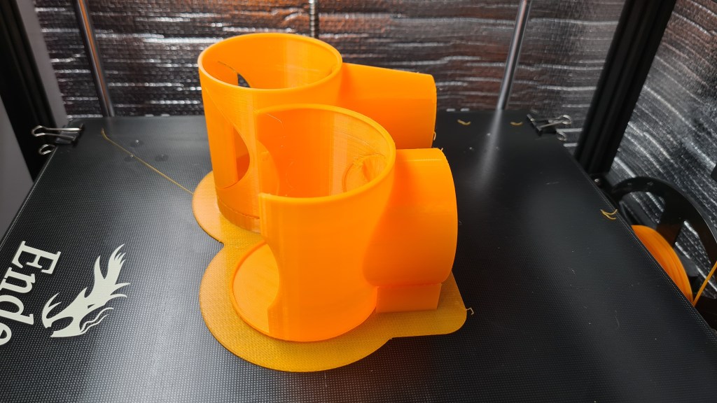
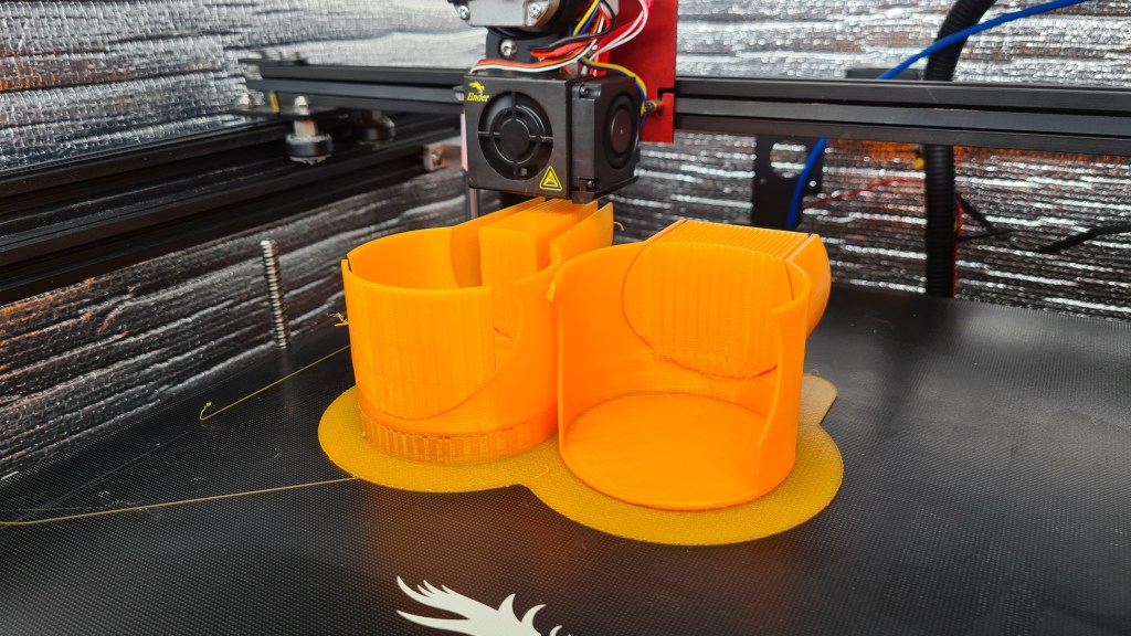
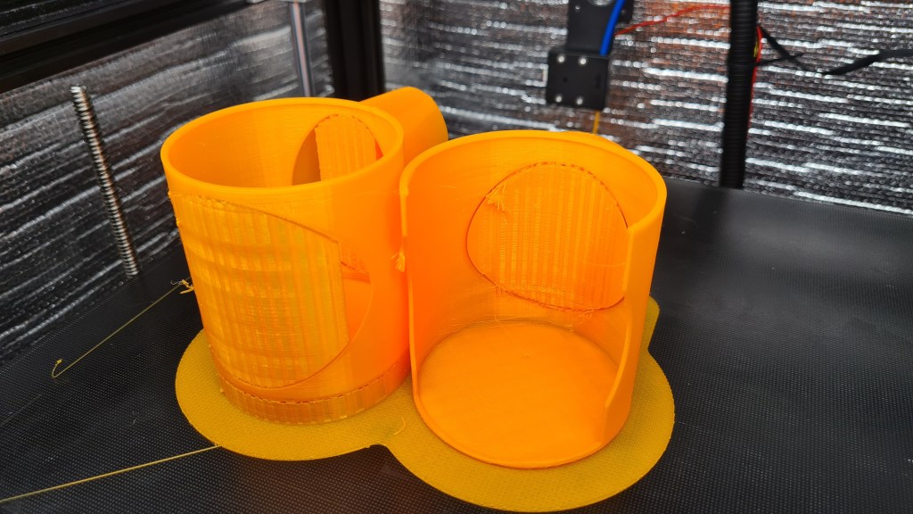
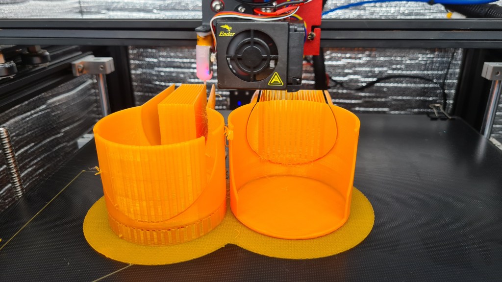

Well, I think it was worth waiting. 🙂
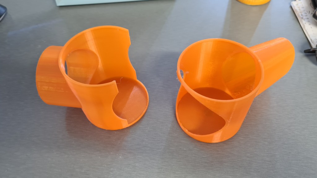
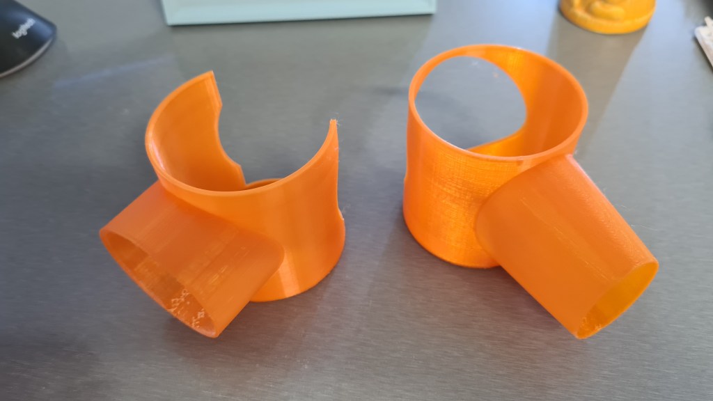


All clicked together and moving smoothly. I was surprised how nicely it actually worked out. Still, there are few things to improve:
Still it looks beautiful for a first try 🙂
I’ve been reading most of the evening about the Shipping (or Intermodal) containers. There are several very well written wiki pages on this topic, full of very interesting information starting with the Containerization history and going through the ISO Container itself all the way to the Emma Maersk. So FYI I’ll be quoting number of those in this article, just because I wouldn’t be able to write it better – all credits to the Wikipedia.org for this amazing source of knowledge.
Well, why containers? As per Wikipedia:
Before containerization, goods were usually handled manually as break bulk cargo. Typically, goods would be loaded onto a vehicle from the factory and taken to a port warehouse where they would be offloaded and stored awaiting the next vessel. When the vessel arrived, they would be moved to the side of the ship along with other cargo to be lowered or carried into the hold and packed by dock workers. The ship might call at several other ports before off-loading a given consignment of cargo. Each port visit would delay the delivery of other cargo. Delivered cargo might then have been offloaded into another warehouse before being picked up and delivered to its destination. Multiple handling and delays made transport costly, time consuming and unreliable.
Wikipedia

There were multiple container systems developed through the history, but its golden age haven’t came until after World War II, when it dramatically reduced the costs of transport, supported the post-war boom in international trade, and was a major element in globalization.
Today (2020), 90% of non-bulk global cargo is moved by containers stacked on transport ships, where 26% of all container transshipment is carried out in China.

There were plenty sizes and many of them had some pretty funny reasoning like the “New 35 ft (10.67 m) x 8 ft (2.44 m) x 8 ft 6 in (2.59 m) Sea-Land container”, which had its length determined by the maximum length of trailers then allowed on Pennsylvanian highways. Today there are five common standard lengths:
20 ft (6.10 m)
40 ft (12.19 m)
45 ft (13.72 m)
48 ft (14.63 m)
53 ft (16.15 m)
20 and 40 ft are the most common, while the larger ones are mostly dedicated to the US market.
Values apparently vary slightly from manufacturer to manufacturer, but must stay within the tolerances dictated by the standards (ISO 668:2013). Empty weight (tare weight) is not determined by the standards, but by the container’s construction, and is therefore indicative, but necessary to calculate a net load figure, by subtracting it from the maximum permitted gross weight.
Wikipedia
So the 20 ft container comes with following values:
The 40 ft container comes with following values, which are practically a double of that 20 ft, except the Maximum gross weight, which quite surprisingly remains the same:

Now you might be bit confused why I made you to read all that above, but I actually don’t think you are. Still, let’s let it hanging in the air and watch some super-amazing video on how Shipping container Gantry Cranes work at Dublin.
In preparation to our EDF testing I thought to get a proper power supply and after several consultations with Risa we’ve picked one for $86.88 from eBay which should provide 30V with up to 10A.
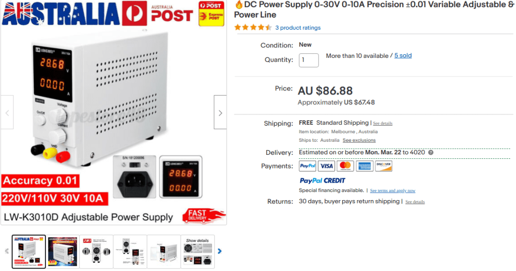
Features:
– This is a regulated DC power supply which you can adjust current and voltage continuously.
– Dual LED display of voltage and current, high precision.
– Energy-saving and efficiency: over 80% power, 40% higher than other liner power supplies.
– Intelligent temperature control: adjustable fan revolving speed based on load power, noise reduced and life – prolonged.
– Safe and reliable: overload protection, overheating protection, overvoltage protection, short-circuit protection, etc.
– Input voltage is switchable(AC110V/AC220V) through the switch on the back of the instrument.
– Can be used in the electronic circuit such as the operational amplifier, digital logic circuit and so on.
– Suitable for electron fans, research people and the professional people.
– It can be widely used in production line test, electrical maintenance, aging products, battery charging, laboratories, scientific research and teaching and many other areas.
Specification:
Output: DC0-30V, 0-10A
Input Voltage: AC110V/220V ±10%
Frequency Range: 50/60Hz
Load Regulation:<=0.3%+5mV
Ripple: <=10mVrms
Operating Temperature: 0°C-40°C
Display accuracy: ±0.01
| Condition: | New | Brand: | LONGWEI |
| Output Current Range:: | 0~10A | MPN: | BmI2793452 |
| Voltage Display Accuracy:: | ±0.5% | Maximum Current Output: | 10 A |
| Current Display Accuracy:: | ±0.5% | Maximum Voltage Output: | 30 V |
| Efficiency:: | >85% | Adjustable Power Supply Type: | Switch-Mode Power Supply (SMPS) |
| Operating Ambient:: | -10℃ ~ 60℃ / 30%RH~ 90% RH | Model: | LW-K3010D |
| EAN: | 6926646376399 | Input Voltage:: | AC 110-240 V / 50~60Hz |
| upc: | 6216809853851 | Output Voltage Range:: | 0~30V |
| Manufacturer Part Number: | BmI2793452 | UPC: | 6443193440507 |
| ISBN: | Does not apply |
Package arrived in a week time – just for our weekend experiments.


There was a mains cable, but these cables for that front banana plug are missing. So another trip to JayCar tomorrow awaits.

Have you ever thought how would an airship land on aircraft carrier? This very interesting situation actually happened! On 27 January 1928 the 200-meter-long airship USS Los Angeles landed on aircraft carrier USS Saratoga.
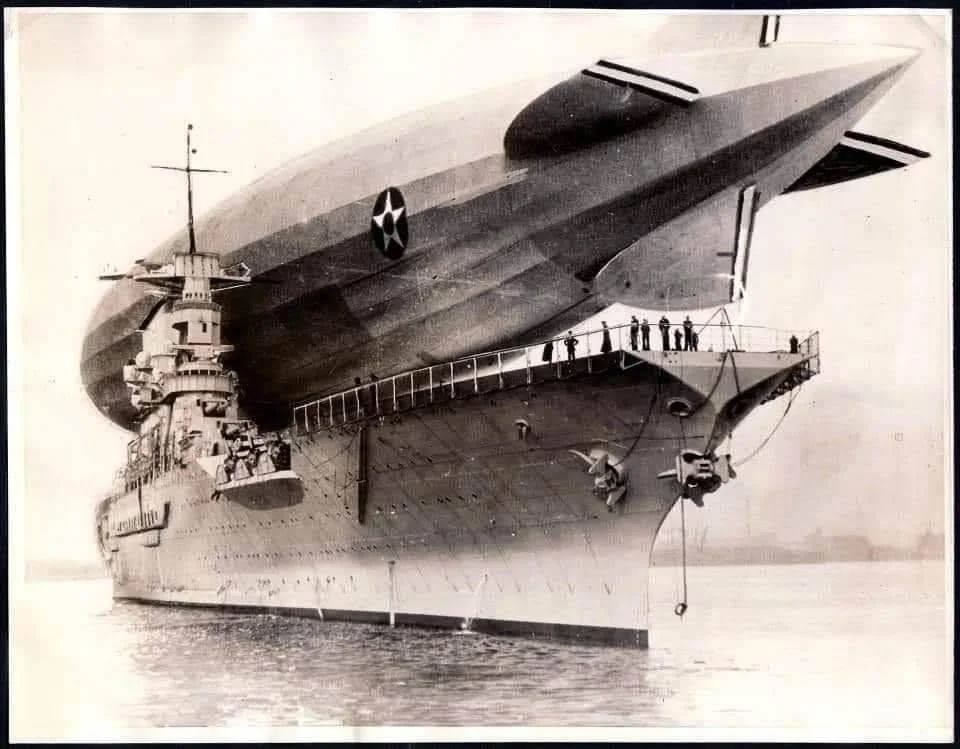
I’ll quote here couple paragraphs from the “DEPARTMENT OF THE NAVY — NAVAL HISTORICAL CENTER” which also briefly mentions this event.
USS Los Angeles, a 2,472,000 cubic foot rigid airship was built at Friedrichshafen, Germany. Her construction was partially funded by German World War I reparations and was conditional on her being employed for “civil” purposes. Completed in August 1924 under the builder’s number LZ-126, she departed Germany in mid-October 1924 for delivery to the U.S. Navy. After a three day trans-Atlantic flight, the airship arrived at Naval Air Station Lakehurst, New Jersey, where her hydrogen lifting gas was replaced with non-flammable helium. This greatly increased her safety, but also significantly reduced her payload and range. In late November 1924 she was placed in commission as USS Los Angeles and began several years of flight activity to explore the potential of her type for commercial and Naval use. Between February and May 1925, she voyaged twice to Bermuda and one time to Puerto Rico, and made test moorings to the Navy’s floating airship base, the oiler Patoka.
In June 1925, Los Angeles began an overhaul at Lakehurst, while her expensive helium gas was transferred to the older dirigible Shenandoah (ZR-1). The latter’s tragic loss, on 3 September 1925, produced a temporary shortage of helium, delaying Los Angeles’ return to flight service until March 1926. However, she was actively employed for six years after that, five of them as the Navy’s only rigid airship. During this time, in addition to her normal training and experimental duties, she was used to calibrate East Coast radio compasses, made several cross-country flights around the eastern and southern United States, landed briefly on the aircraft carrier Saratoga and continued her work with Patoka. A unique incident on 25 August 1927, in which she briefly rose tail-high to a near-vertical position while attached to Lakehurst’s tall mooring mast, demonstrated the dangers inherent with this type of facility and led to the adoption of the “stub” mast used for more than three more decades of dirigible and blimp operations.
Being there, I couldn’t resist and downloaded some of the USS Los Angeles pictures – many of them are well known and practically iconic.


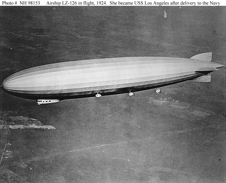


Then I suddenly remembered one of my previous posts and did some colouring. Enjoy! 🙂

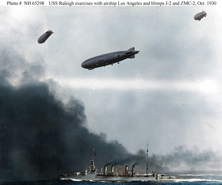
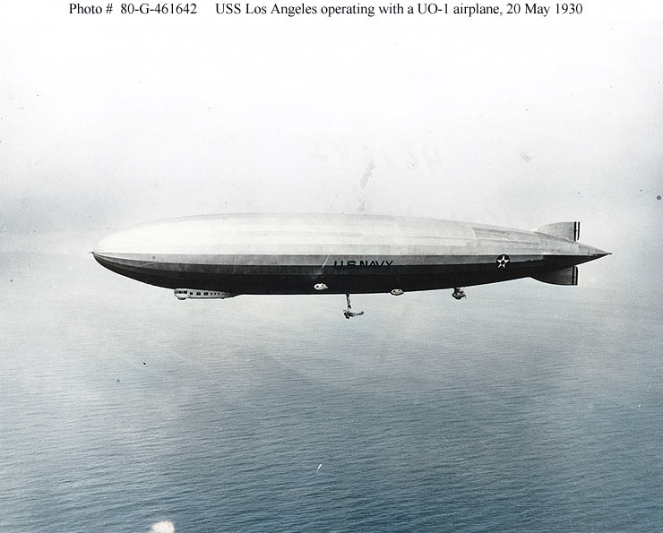
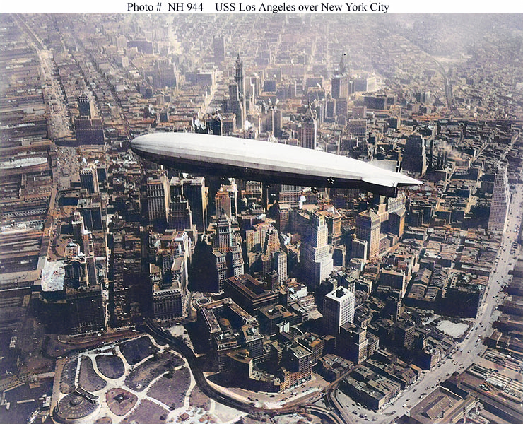

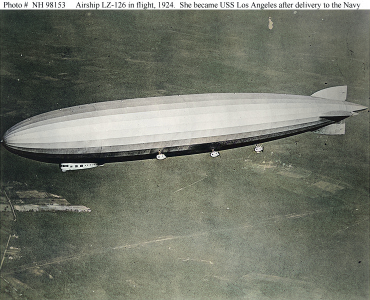


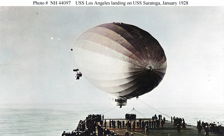
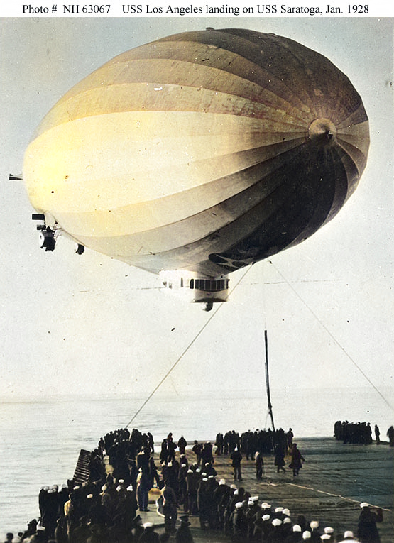
Sebi progressed very quickly and put together a remote-controlled Dynamic Speed Controller. I made him, Oli and Eddie to do a tiny Demo for us:
Sebi’s been working on a little project on his own – Dynamic Speed Controller – for our EDF (Electric Ducted Fan), actually making it to respond to manual controls.
Materials:
– Slide Potentiometer
– Seeeduino XIAO
– 10 wires
– 2 red LEDs
– 5v USB battery pack
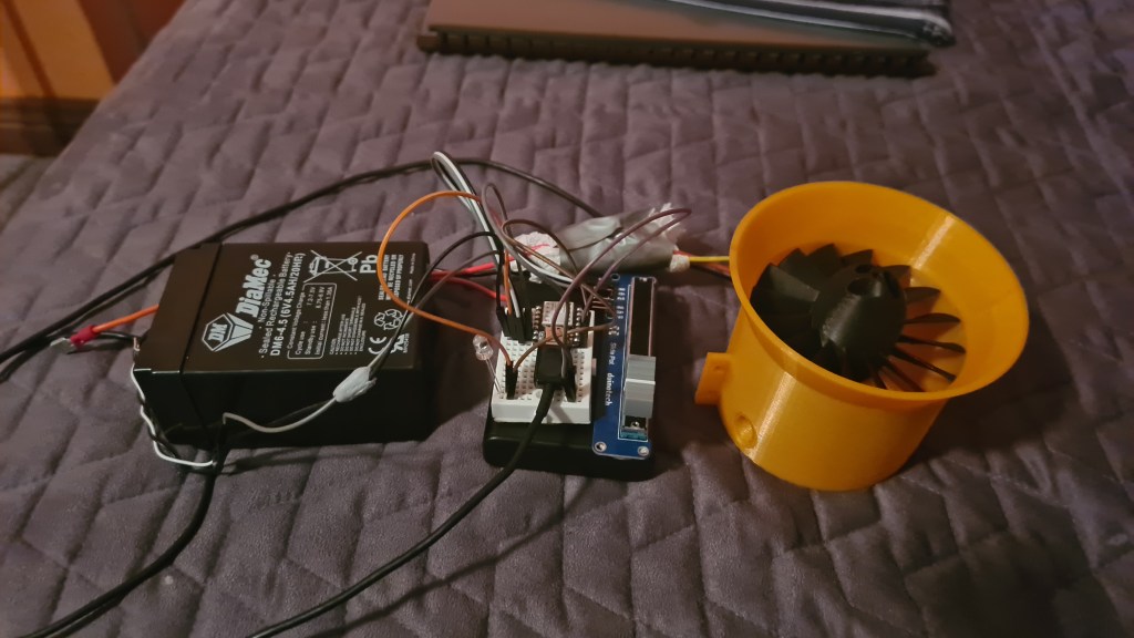
Sebi loaded the Arduino with following code:
#include <Servo.h>

const int analogInPin = 10;
const int digitalOutPin = 1;
const int analogOutPin = 0;

Servo ESC;

int sensorValue = 0;
int outputValue = 0;
int servoValue = 0;

void setup() {
  Serial.begin(9600);
  pinMode(digitalOutPin,OUTPUT);
  ESC.attach(9,1000,2000);
  ESC.write(0);
  delay(1000);
  ESC.write(50);
  delay(1000);
  ESC.write(100);
  delay(1000);
  ESC.write(180);
  delay(1000);
}

void loop() {
  sensorValue = analogRead(analogInPin);
  servoValue = map(sensorValue, 0, 1023, 0, 180);

  Serial.println(sensorValue);
  Serial.println(servoValue);

  analogWrite(analogOutPin, sensorValue);
  ESC.write(servoValue);

  if (sensorValue == 1023) {
    digitalWrite(digitalOutPin, HIGH);
  } else {
    digitalWrite(digitalOutPin, LOW);
  }

  delay(15); //waits for servo to get there?
}
We had Roman & Lili for a dinner so Roman bravely gave it a go.
He had a hard time not to fly away!
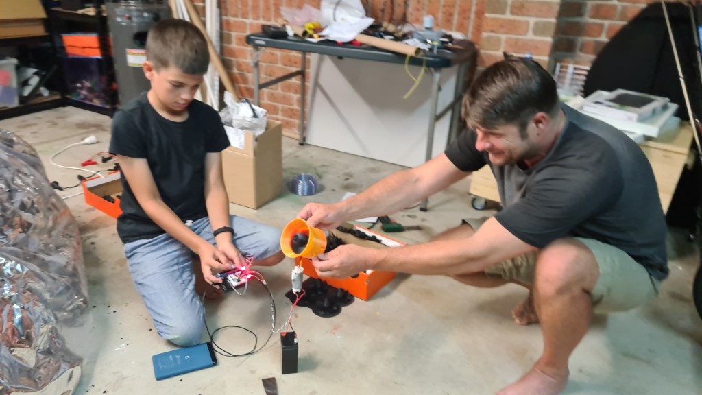
Stay tuned, Sebi already announced a new stage – the Remote Controlled Dynamic Speed Controller!

Serge came precisely at 4pm as agreed and before we’ve agreed on the plan … Richie appeared as well! So we went straight to the action and Serge mounted the pressure regulator together with the hose.
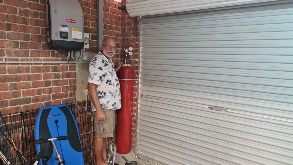
It actually took several iterations with Richie it leaking.
Soon after Sebi tested if that gas in the bottle is the Hydrogen, or any other interesting gas.

Balloon filling started ~ 5:45pm in front of our garage and many came to observe whether our little high-school project.


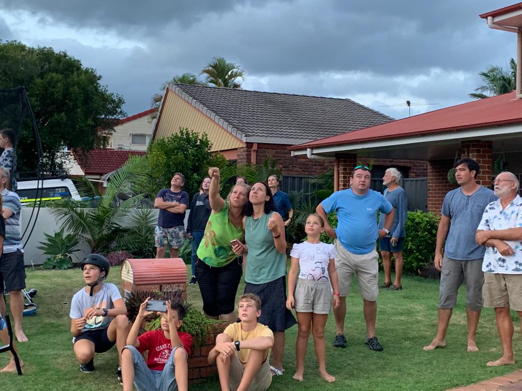


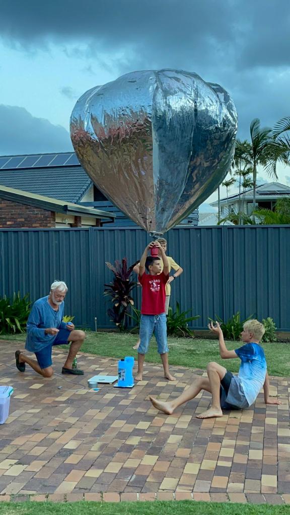
We had kids to have a guess on how much lifting power we’ll generate with our balloon – the prize goes to Cara and Timo!

Everything ready to go!

And we have a lift off!
Thank you all for coming and your great support! It was amazing atmosphere you prepared, thank you!

This release wraps up our Phase II and we are onto the Phase III now.
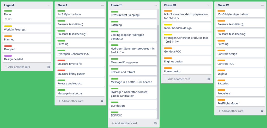

Rough plan follows:
5:00 pm – start filling our balloon from the Hydrogen gas canister in front of the house
5:50 pm – attach the beacon and carry on last tests (it flashes + holds well)
6:00 pm – balloon release
6:13 pm – sunset
Weather forecast – sunny and comfortable 26.9C.

Wind forecast – gentle and easterly (Agreement with Serge is that we’ll always release over the land not to waste the sea).

All the team Blimp welcome to join for a historic moment observation! 🙂
In the post “Dr. Hydrogen or: How I Learned to Stop Worrying and Love the Bomb” I’ve got a Hydrogen canister and bolted it to the wall in the garage as missing an option to release the gas safely. Luckily there is no expiry date on the Hydrogen usage, so there is no rush, except that renting that canister from BOC comes to ~$1 a day.
Meanwhile I kicked-off an investigation on “How to obtain a hydrogen pressure regulator in Queensland” and through various options I’ve ended up ordering the one straight from BOC for bargain $472.70.
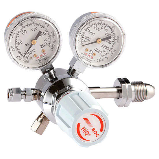

This is a place where I send a huge thanks to all who sponsored me in buying this regulator – starting with Jirus, my Mum, Vlada and Veronika! Huge thanks!

The Regulator arrived shortly in a nifty cardboard box and I enjoyed unpacking it with Eddie. It feels really solid and in a mechanical sense … beautiful. 😉
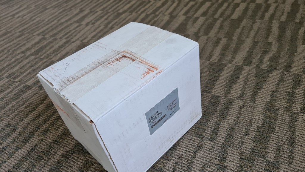
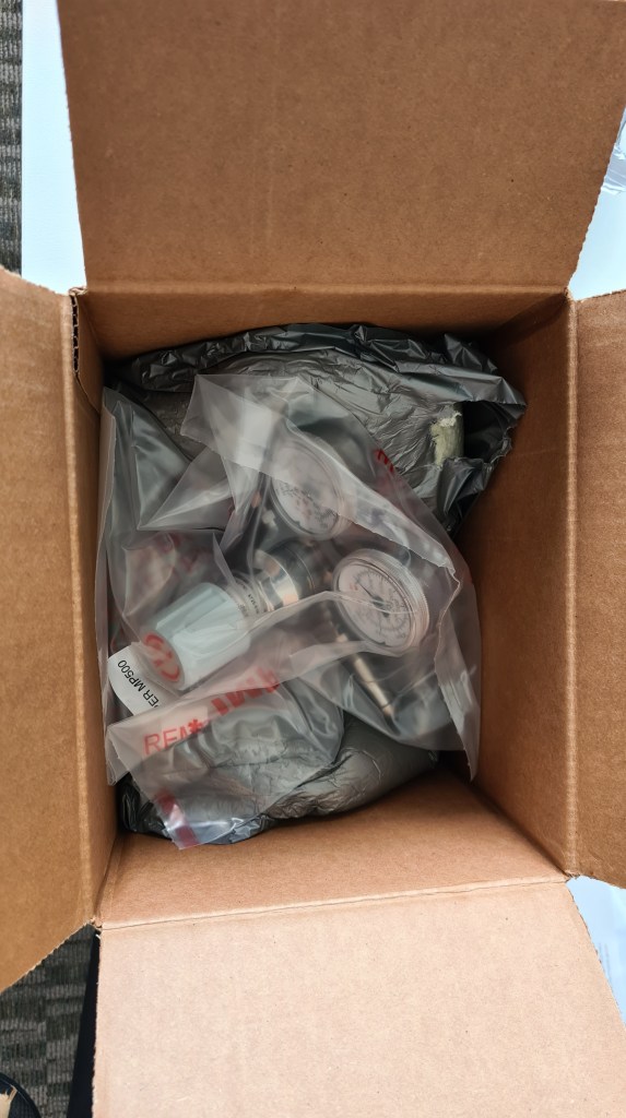
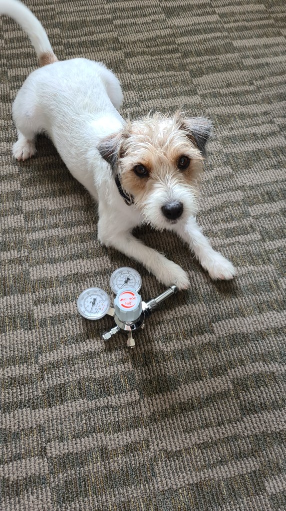
I also too few more pics for Serge to get his advice on how to actually use it.
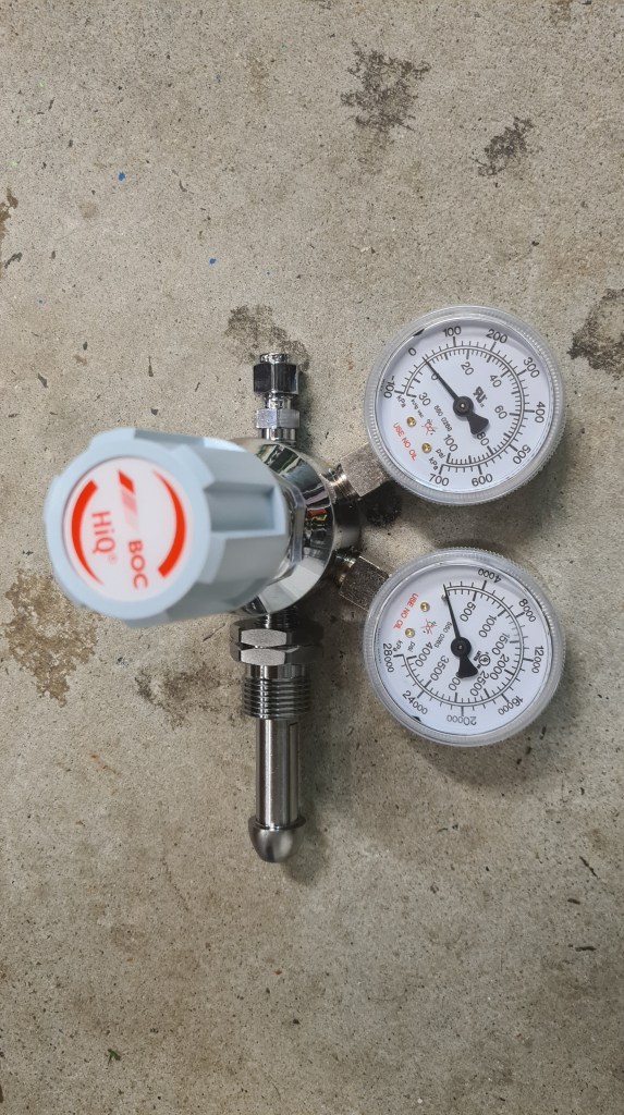


As you see the hole size, based on the super calipers, we need 6 mm copper tube to be able to connect it.

And couple days later Serge (and Robin) got it all working. Now we are finally ready for some serious blimp-action!
As discussed before we need multiple EDFs (Electric Ducted Fan) to push our blimp through the air. So I started thinking how to build it internally. The plan is to build something like on a picture below (see original article here), while wrapping the EDF unit around the motor there.

I did some shopping first:
1/ 4x Racerstar RS30A Lite 30A Blheli_S 16.5 BB1 2-4S Brushless ESC Support Dshot150 Dshot300 for RC Drone

2/ 1x Racerstar BR2830 1300KV 2-4S Brushless Motor For RC Airplane

Followed with some nice EDF design:
And after months it all together looks like this:
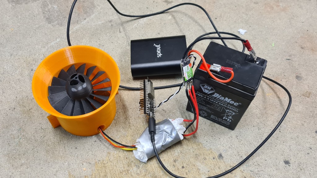
Not knowing much about ESCs (Electric Speed Control) I’ve put together a tiny program to explore how to operate it “brute force”. Following code starts sending speed signal to the motor starting with value 50 and scaling up to 110 and back. Then it stops.
#include <ESP32Servo.h>
#include <Streaming.h>

Servo myservo;  // create servo object to control a servo

// Possible PWM GPIO pins on the ESP32: 0(used by on-board button),2,4,5(used by on-board LED),12-19,21-23,25-27,32-33
int servoPin = 18;      // GPIO pin used to connect the servo control (digital out)
// Possible ADC pins on the ESP32: 0,2,4,12-15,32-39; 34-39 are recommended for analog input
int potPin = 34;        // GPIO pin used to connect the potentiometer (analog in)
int ADC_Max = 4096;     // This is the default ADC max value on the ESP32 (12 bit ADC width);
                        // this width can be set (in low-level oode) from 9-12 bits, for a
                        // a range of max values of 512-4096

int val;    // variable to read the value from the analog pin

void setup()
{
	// Allow allocation of all timers
	ESP32PWM::allocateTimer(0);
	ESP32PWM::allocateTimer(1);
	ESP32PWM::allocateTimer(2);
	ESP32PWM::allocateTimer(3);
  myservo.setPeriodHertz(50);// Standard 50hz servo
  myservo.attach(servoPin, 500, 2400);   // attaches the servo on pin 18 to the servo object
                                         // using SG90 servo min/max of 500us and 2400us
                                         // for MG995 large servo, use 1000us and 2000us,
                                         // which are the defaults, so this line could be
                                         // "myservo.attach(servoPin);"
}

static inline unsigned get_ccount(void)
{
        unsigned r;
        asm volatile ("rsr %0, ccount" : "=r"(r));
        return r;
}

void loop() {
  //while (!Serial);
  Serial.begin(9600);
  while (!Serial);
  //Serial.print ("hello world");

  bool up = true;
  float speed = 50;

  //Arm
  Serial << "arming" << endl;
  myservo.write(70);
  delay(5000);
  Serial << "arming done" << endl;
  while (true) {
    time_t _time;
    time(&_time);

    /*val = analogRead(potPin);            // read the value of the potentiometer (value between 0 and 1023)
    val = map(val, 0, ADC_Max, 0, 180);     // scale it to use it with the servo (value between 0 and 180)
    myservo.write(val);                  // set the servo position according to the scaled value
    */
    if (_time > 50)
      break;

    if (up)
      speed += 0.1;
    else
      speed -= 0.1;

    Serial << "[" << _time << "] speed: " << speed << endl;

    myservo.write(speed);
    delay(50);

    if (speed < 50)
      up = true;
    else if (speed > 110)
      up = false;
  }

  myservo.write(0);

}
Having all together we started doing some testing with the assistance of Richard, Adam, Vilem and Martin. We started with 4.6V battery, but that didn’t seem to give a proper umpf so we quickly moved to the 12V car battery (3 cells). The very first test got documented on video. 🙂
Next stage included propeller replacement (PLA -> ABS) and another boost – getting the 16.8V lithium-Ion-4-cell battery. Note the multi-meter – it is reaching almost 10 Amps – that makes it some serious 168W output!
We had few more runs, while the final one came with the idea to check if we have enough thrust to actually start moving things … and it felt great!
Couple months back I’ve prepared a GitHub repository to store all the models.

It can be that you don’t know what GitHub is – so with a help from Wikipedia:
GitHub, Inc. is a provider of Internet hosting for software development and version control using Git. It offers the distributed version control and source code management (SCM) functionality of Git, plus its own features. It provides access control and several collaboration features such as bug tracking, feature requests, task management, continuous integration and wikis for every project.
GitHub offers its basic services free of charge. Its more advanced professional and enterprise services are commercial.
Wikipedia
Well, this is almost silly, but after reading above you probably wonder what Git is – so with another help from Wikipedia:
Git (/ɡɪt/) is a software for tracking changes in any set of files, usually used for coordinating work among programmers collaboratively developing source code during software development. Its goals include speed, data integrity, and support for distributed, non-linear workflows (thousands of parallel branches running on different systems).
Developed created by Linus Torvalds.
Wikipedia
So what to do about it? Practically the easiest way is to visit the bbblimp project page on GitHub. There you can access all software resources for our blimp project, including OpenScad source code, Cura (3D printing) projects and some actual STL models.
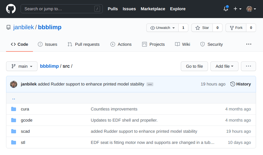
Clicking on a file you can see its history and particular changes between each commits.
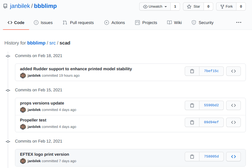
Now, why all that hustle? Actually this is super-handy. I really like our project and this public storage makes an excellent backup for all its resources. And not just this, all those are stored with their own history and accessible from anywhere. Finally, it also allows efficient collaboration and development on those.
If you’ve got all the way here, you are probably getting close to the bored-to-death stage, so a little nerdy reward in form of few jokes I found on Google (fun not guaranteed if you read about Git in this article for a first time in your life).

At some stage, when trying to solder two cables together and needed to hold them together including soldering iron and the soldering paste, I’ve realised that I simply need couple more hands. Discussing this with Andrew he suggested a “Third hand tool“. Bit of a research revealed “NEWACALOX LED 3X Magnifier Bench Vise Table Clamp Soldering Helping Hand Soldering Station USB 5pc Flexible Arms Third Hand Tool“.
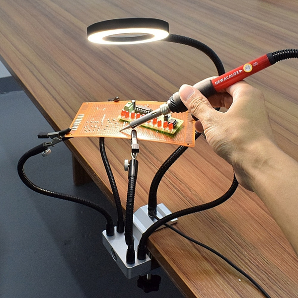
I wrote to Santa and he came back with it and it is awesome. Mainly Sebi enjoys it a lot. 😉


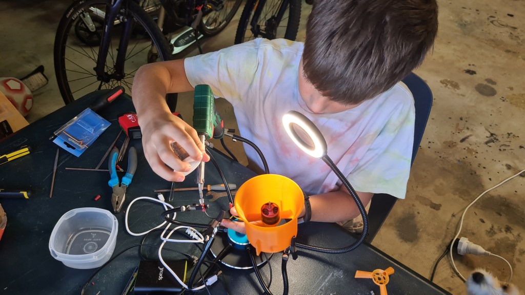
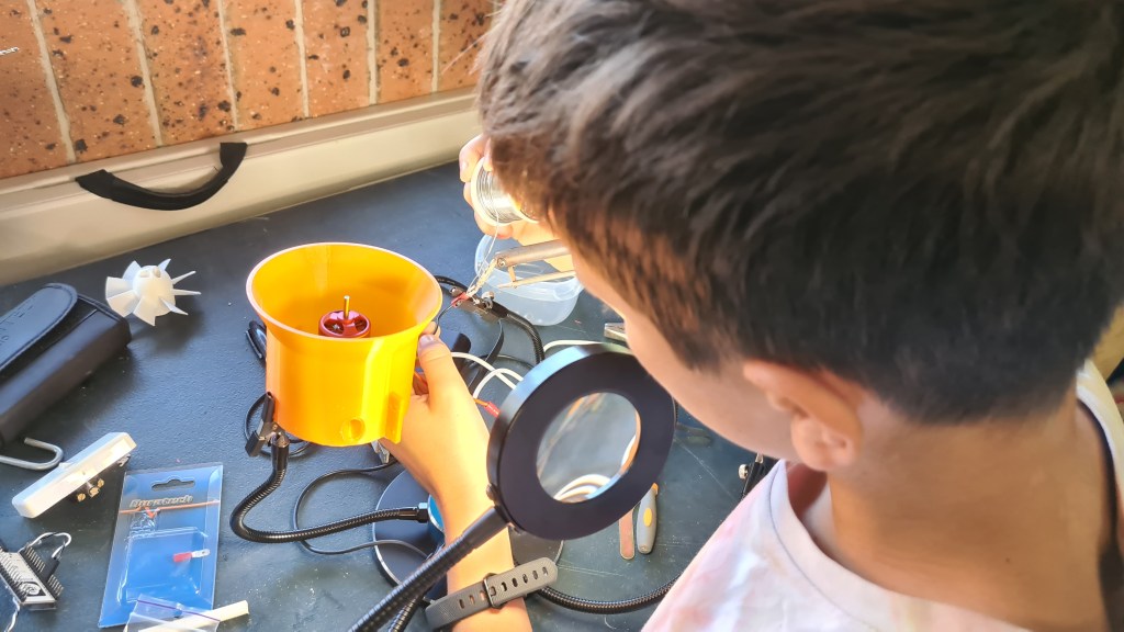
Just yesterday we’ve been browsing through some of our archive pictures with Veronika and noted following ones in the folder called “2011 – 02 – 23 Londyn science museum & hyde park”.

I made a quick transcript.
Dinosaurs of the Air
Early airships used gas pressure to keep their shape, but this only suited small craft. From 1900 Count Ferdinand von Zeppelin experimented with much larger rigid airships. In these an outer skin covered a framework of aluminum girders. Inside, separate gas bags held hydrogen.
There were many crashes. The huge size made the ships hard to control and they were always at risk from bad weather. But contemporary aeroplanes had a short range so airships were attractive for passengers or for war. During the First World War, German Zeppelins were used for naval patrols and for bombing but proved vulnerable.
After the war many countries tried Zeppelin-type airships, but accidents were common. Even the use of non-flammable helium gas in America did not make them safe. Three great helium-filled airships, Swanborough, Acron and Macon, all crashed with loss of life. After the last disaster the USA gave up airships as did Britain after the loss of the R101 in 1930.
Only the Zeppelin company, with its core of skilled technicians and crew operated airships reliable and the passengers-carrying “Graf Zeppelin” performed notable flights for several years. However, when its successor, the “Hindenburg”, caught fire on landing at Lakehurst in New Jersey in 1937 it market the end of the rigid airships.
In a curious epilogue to the airship age the “Graf Zeppelin II” flew some final mission on the eve of the Second World War. Equipped with radio technicians and electronics it cruised off the coast in May 1939 to find out if Britain had a radar warning system. It was in fact, followed on the Chain Home screens, but aboard the airship the crew failed to detect the transmissions.
Plus there was one more. I’ll try to identify those another day.
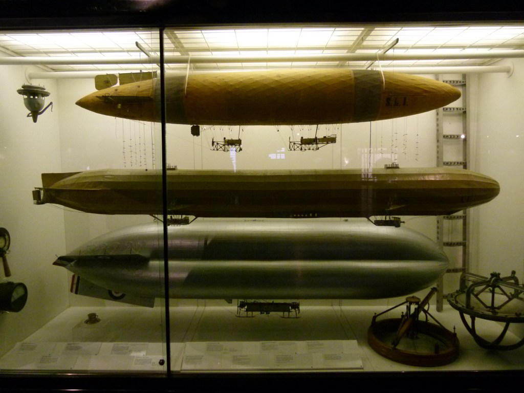
You may wonder where post named “Hydrogen generator Mk. VII” went, when there my last update on the this topic is “Hydrogen generator Mk. VI“. Well, there was that update on Aluminium corrosion – which practically is another update in that direction so it didn’t fell well not to count it. Even more when there were too many things happening meanwhile.
So just a tiny recap on where we’ve been couple months ago. After the debacle with Aluminium lid, Serge designed a new one, made out of Formica (Bakelite). I did a quick run and all went well so prepared everything for a major run (24hrs). Commencing an over-night run a nasty surprise came following morning, not even Formica can withstand harsh environment of KOH and ~80C for too long.
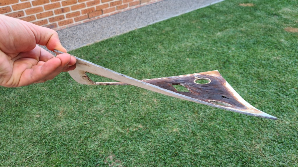
Not just that beautiful bend, but also all bottom of that was lid was covered by “juicy blisters”.

And because it would be too easy to fix the lid on its own, I’ve noticed that electrolyte started somehow leaking into the cooling basin. After scratching my head for a while and failing to explain how that would be happening without an actual hole in the tray, I removed all remaining electrolyte just to find this:
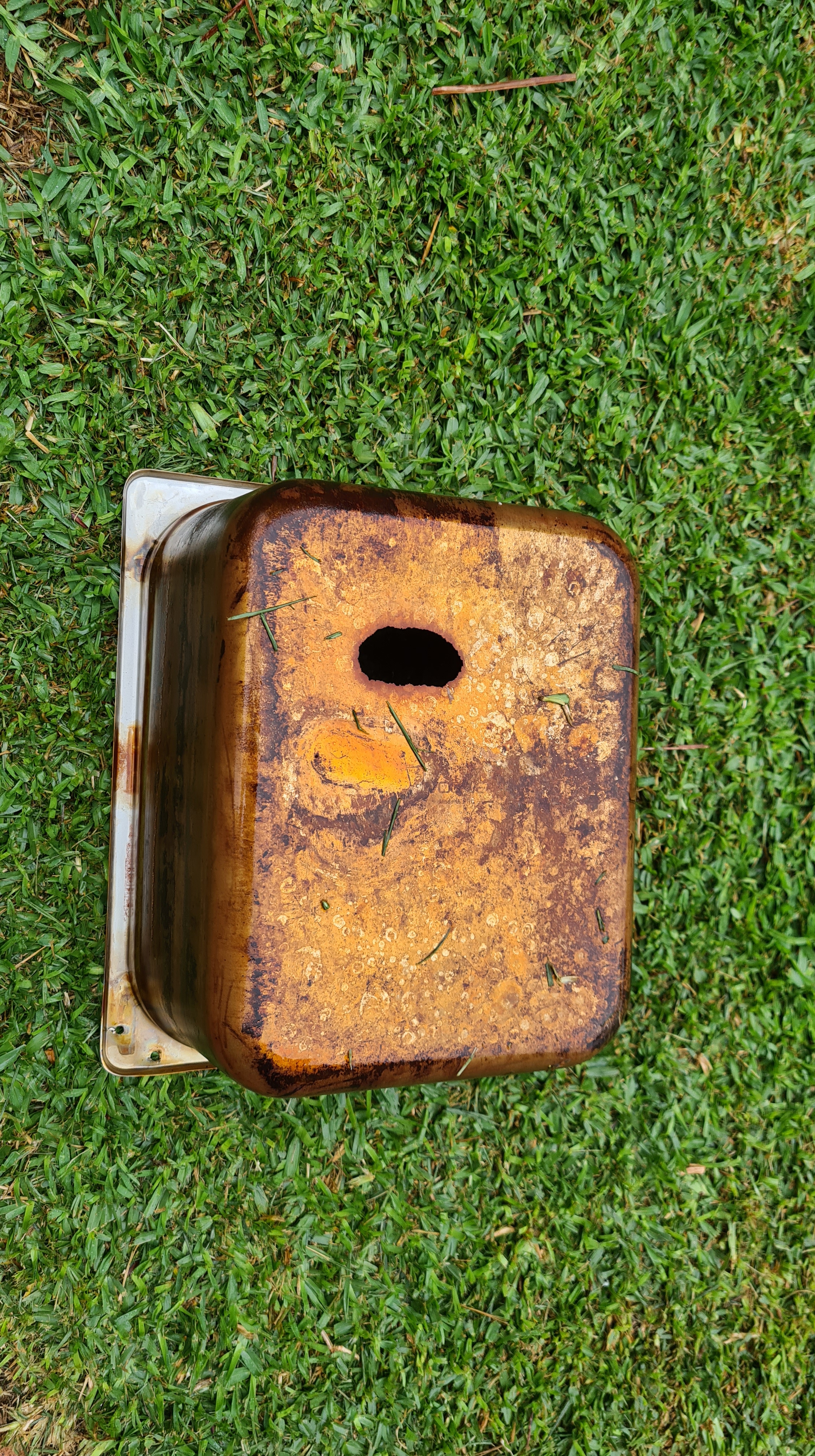
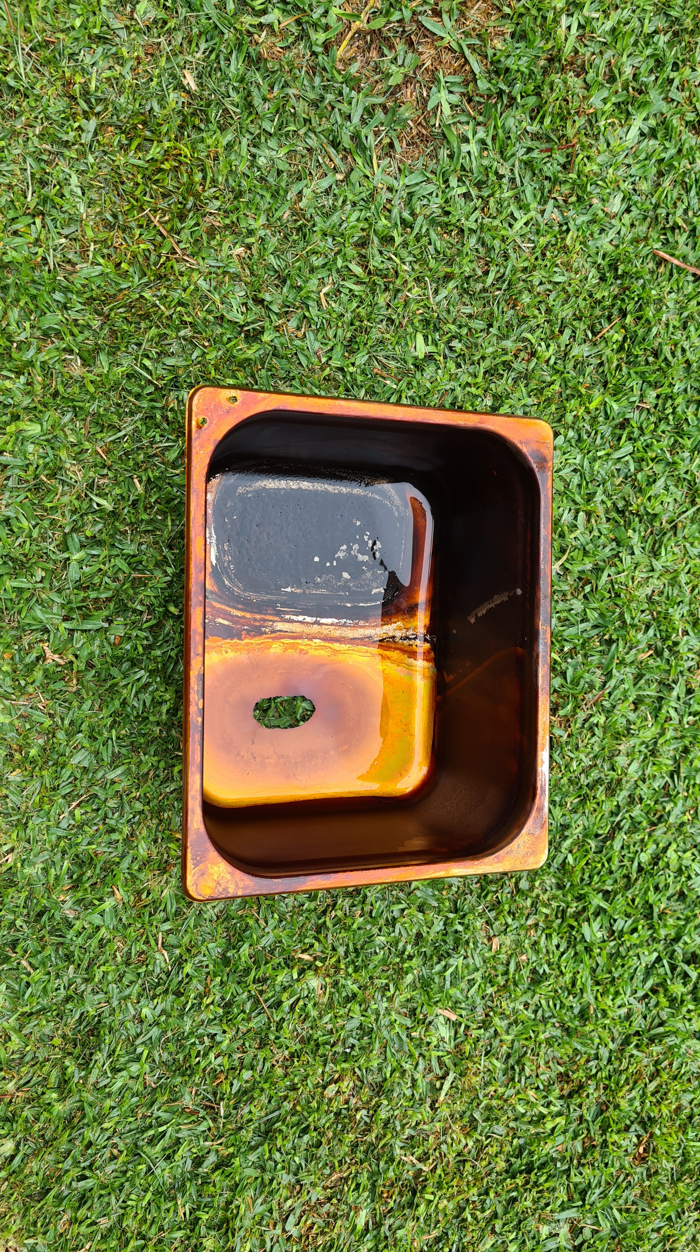
In my naivety I haven’t accounted for a material corrosion on that stainless steel tray – caused by that try being actually grounded! So it is very likely that all the time I was generating hydrogen in this stainless steel tray – it was generating it also around all its surface – and not on the cathode as intended!
Being unable to accept such a straightforward failure I made a quick trip to Nisbets and got whole the same set, but in poly-carbonate. Serge came instantly and ran whole cutting procedure again.


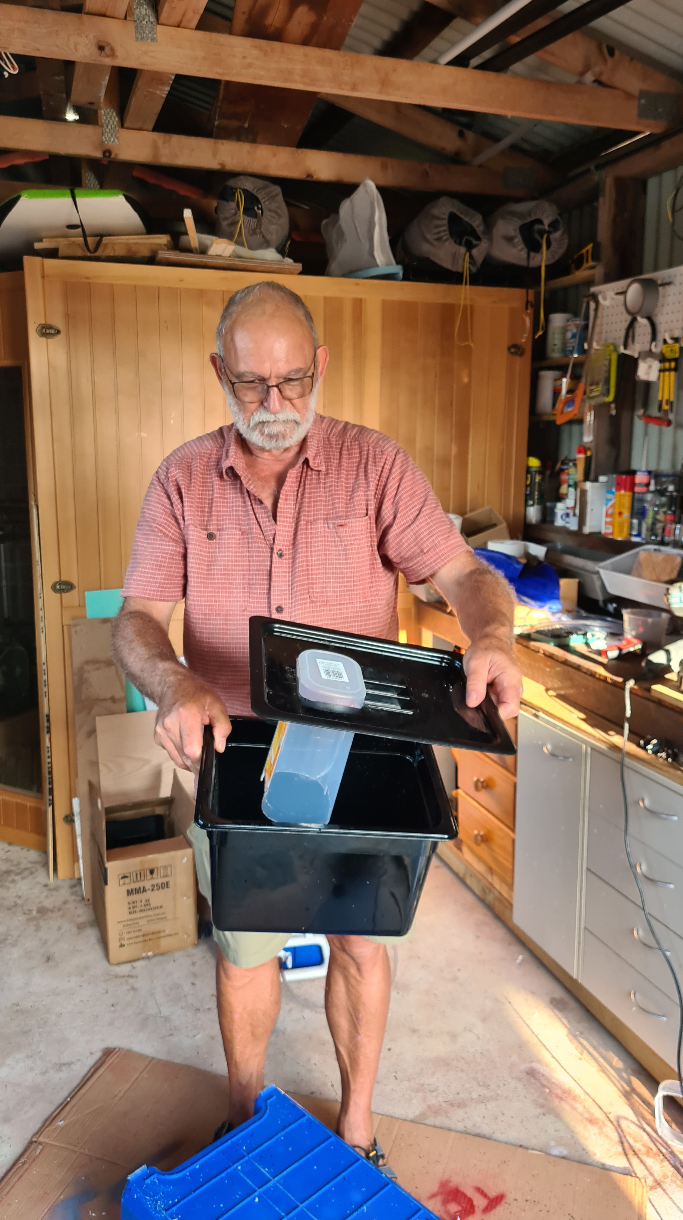

Based on pictures above – I hope you agree – Serge is getting damn good at it! It all starts looking seriously serious. 😀
Anyway, using that new narrow container, as shown on picture 4, caused instantly another problem – overheating. All that poly-carbonate tray together with a limited space for circulation made electrolyte boil in few minutes. Instant solution came to me to replace that hydrogen-capturing container with a bigger one and as we are now getting “seriously serious” I’ve picked “Holman 125mm x 1m PVC DWV Pipe + lid” and converted it to the shape needed.


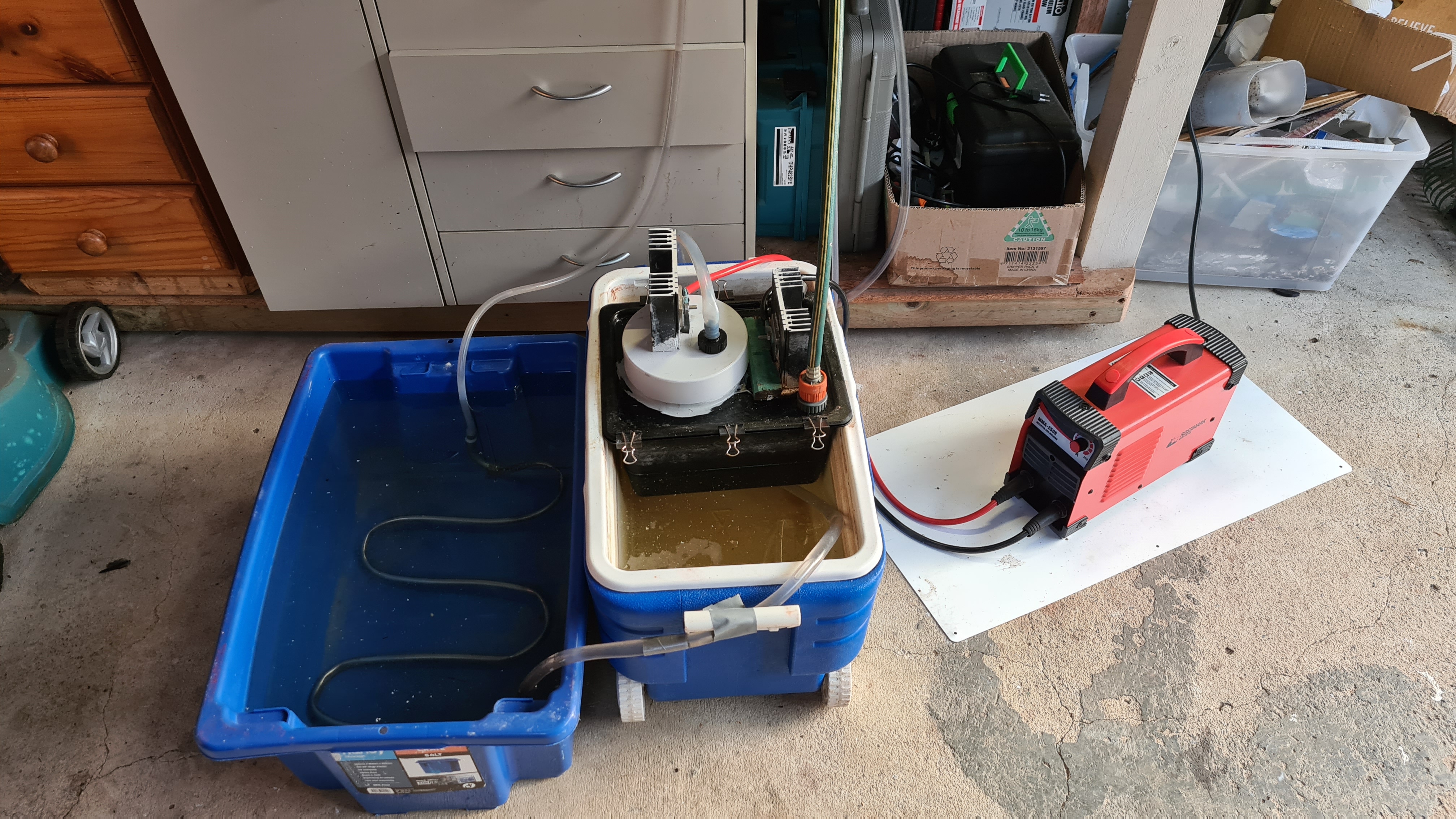
Another run. Couple minutes later into another run, I’ve noticed a new electrolyte leak in to the cooling basin. Counting to ten, I’ve extracted remaining electrolyte into a container and checked that poly-carbonate trey. It broke!
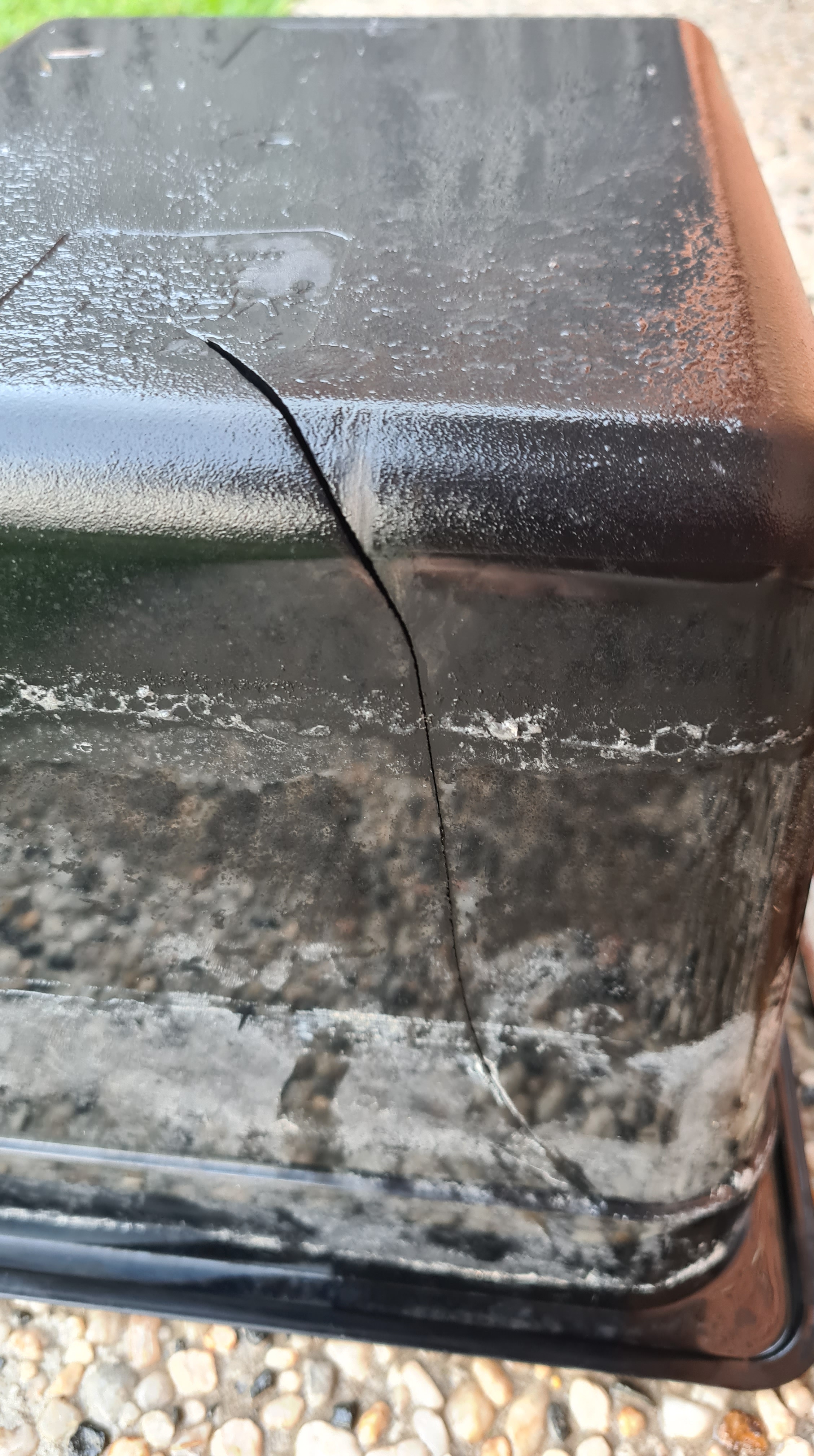
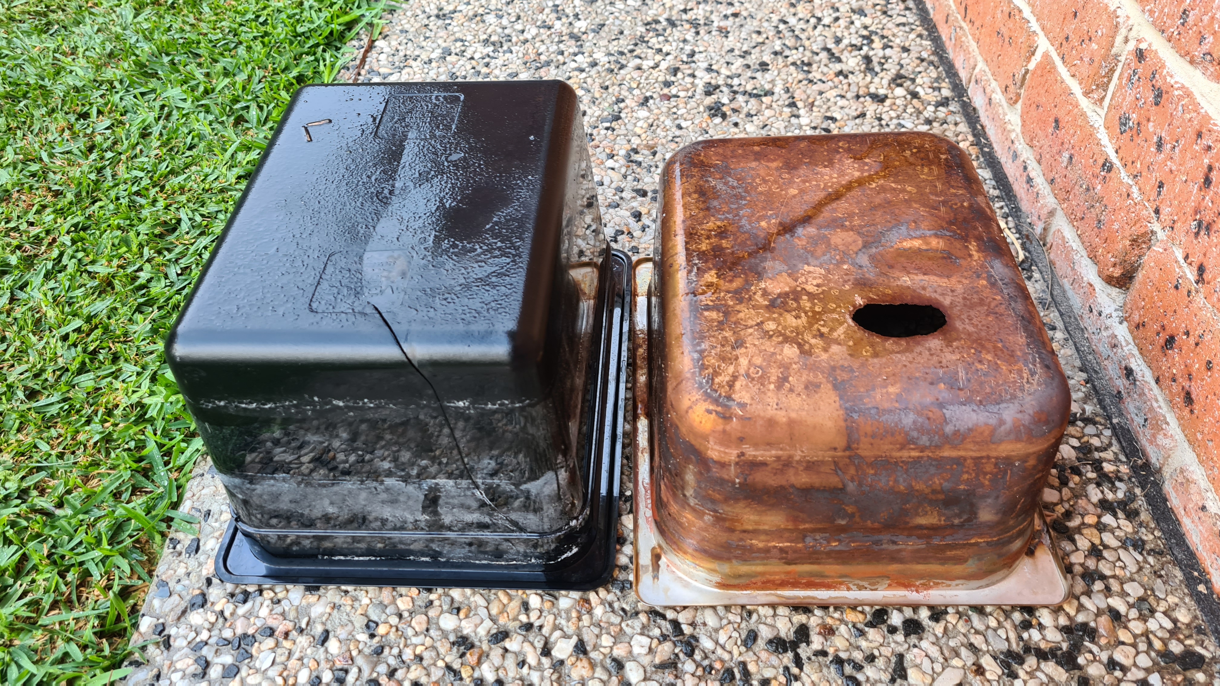
This is actually becoming a museum of Jan’s failures! It really took me couple weeks to digest it and think it through. I’ve been discussing options with many smart brains including Serge, Richard and Greg. Out of the options available I started to incline to get another stainless-steel tray and paint it from inside with Bitumen.
Using bitumen will provide insulation between the electrolyte and a surface of that tray and that’s what’s needed. Problem here is that bitumen seems to be sensitive to a heat and melts in higher temperatures. Also I really need to have a good heat exchange between the electrolyte and the cooling basin to remove all that excessive heat (~30% of energy input). While having couple beers with my friend Vilda, I run him through all that story and he suddenly came with an idea of Teflon!
So, what it is Teflon? Teflon is that black non-sticking part of practically every pan in the kitchen these days.

Reading about it – it actually comes with an interesting story.
Teflon was accidentally discovered in 1938 by Roy J. Plunkett while he was working in New Jersey for DuPont. As Plunkett attempted to make a new chlorofluorocarbon refrigerant, the tetrafluoroethylene gas in its pressure bottle stopped flowing before the bottle’s weight had dropped to the point signalling “empty.” Since Plunkett was measuring the amount of gas used by weighing the bottle, he became curious as to the source of the weight, and finally resorted to sawing the bottle apart. He found the bottle’s interior coated with a waxy white material that was oddly slippery. Analysis showed that it was polymerized perfluoroethylene, with the iron from the inside of the container having acted as a catalyst at high pressure.[3] Kinetic Chemicals patented the new fluorinated plastic (analogous to the already known polyethylene) in 1941,[4] and registered the Teflon trademark in 1945.
Wikipedia
There is also a great in-depth description of “Polytetrafluoroethylene” coming from https://omnexus.specialchem.com/ – clearly worth reading for an even more in-depth understanding of Teflon.
Anyway, even more interesting from my perspective are its characteristics:
| Property | Value |
|---|---|
| Density | 2200 kg/m3 |
| Glass temperature | 114.85 °C (238.73 °F; 388.00 K)[19] |
| Melting point | 326.85 °C (620.33 °F; 600.00 K) |
| Thermal expansion | 112–125×10−6 K−1[20] |
| Thermal diffusivity | 0.124 mm2/s[21] |
| Young’s modulus | 0.5 GPa |
| Yield strength | 23 MPa |
| Bulk resistivity | 1018 Ω·cm[22] |
| Coefficient of friction | 0.05–0.10 |
| Dielectric constant | ε = 2.1, tan(δ) < 5×10⁻⁴ |
| Dielectric constant (60 Hz) | ε = 2.1, tan(δ) < 2×10⁻⁴ |
| Dielectric strength (1 MHz) | 60 MV/m |
| Magnetic susceptibility (SI, 22 °C) | −10.28×10⁻⁶[23] |
From the table above, you can see that Teflon’s melting point is 326C – that is way above what’s needed in our case. Another important parameter is Dielectric constant – which, in simple words, describes material’s resistance to conduct electric current. For example vacuum has this constant equal to 1 (this constant actually uses vacuum as a part of its definition), pure water 80 and copper > 250.000. So our Teflon is actually doing an excellent job here.
Last interesting parameter here is the Thermal diffusivity, which measures the rate of transfer of heat of a material from the hot end to the cold end. With the value of 0.124 mm2/s, our Teflon is not actually our champion at all (gold having 127, while wood 0.082), but if it can be used for cooking, it has to do for us as well.
In comparison with Bitumen – Teflon is clearly our best choice here. Now getting practical – Bitumen can be bought in a nearest Bunnings as a common gutter paint. Unlike Teflon – that actually needs to be sprayed on a surface as a dust and burned onto it in autoclave! Asking Mr. Google where it can be done in Australia, practically the only single place appeared – DECO Australia located in Minto NSW.
I’ve carefully sent them (safe) description of what needs to be done, asking for a quote and they came promptly with not-that-crazy $140 quote. Packaging was fun – our new stainless steel tray made it nicely in one of our used-to-be-welder boxes.
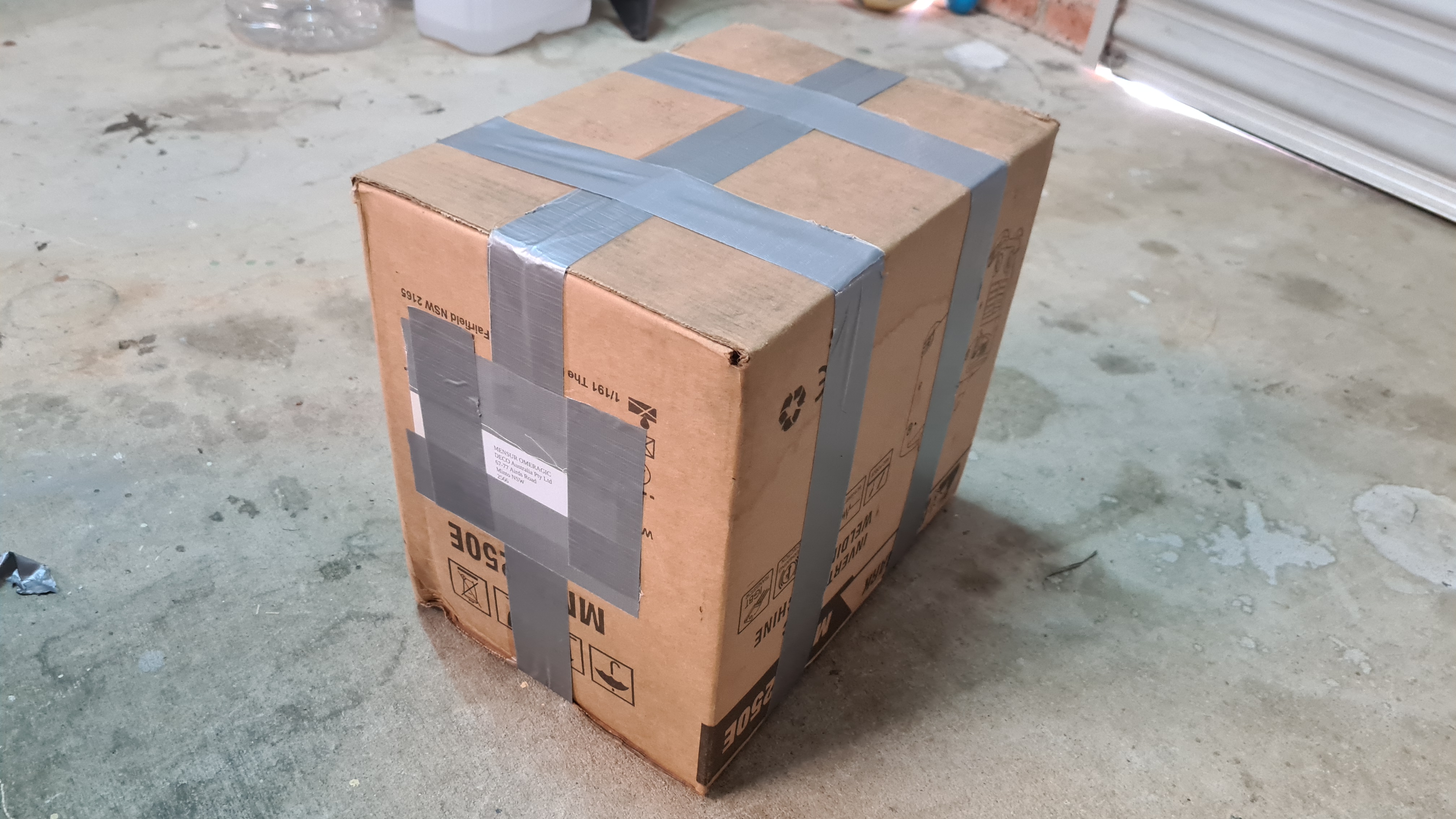


Payment managed by Veronika.

.. and in a couple days our improved tray arrived!

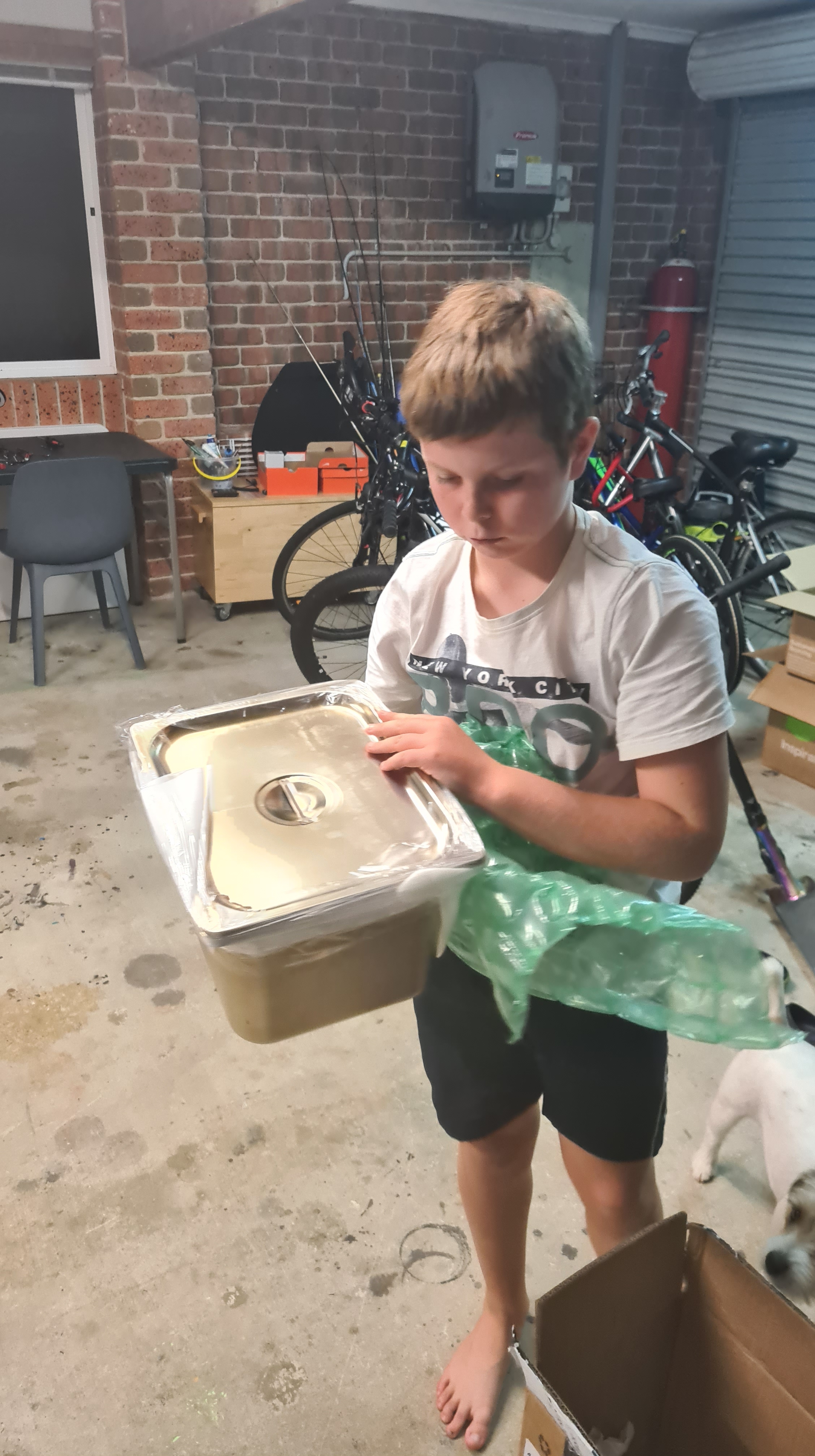


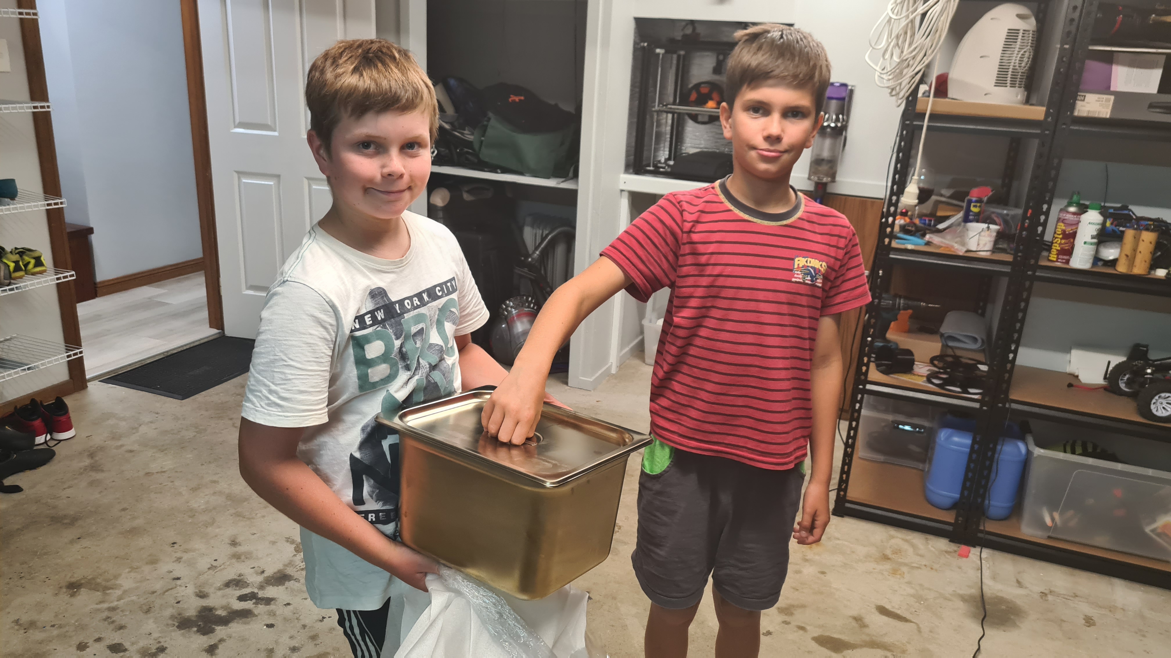
Our next hydrogen run awaits, but that is for another day 😉

Update 2022/12/21:
Received an email from Mr. Paul Martin, coming with a more comprehensive in-depth guide about “Polytetrafluoroethylene” (Teflon), having far more detailed explanation than Wikipedia. I thought it would be a great complement here – relevant section above updated.
Having a great success with previous 3D printer debugging, I decided to move it to a completely different level and come with a final solution involving a wall-mounted fan. I am adding a picture of an initial situation which depicts whole enclosed space being padded with a thermal insulation and a light switch located on right.
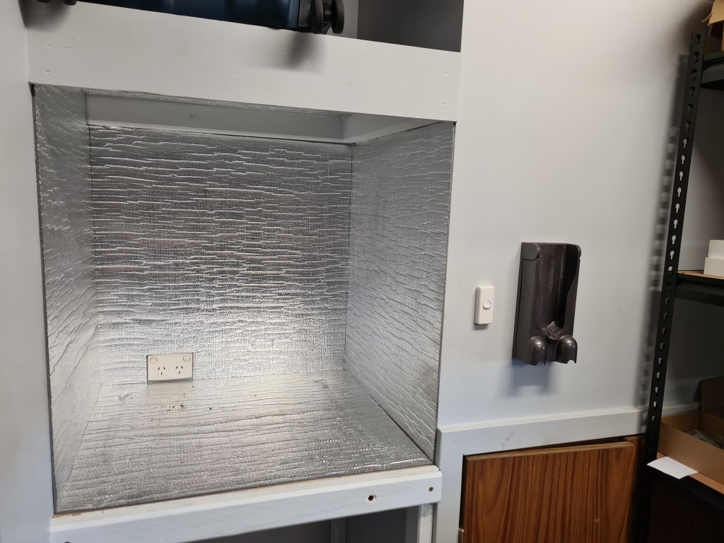
Not to waste time on this, following is a whole procedure documented in a pictures gallery.

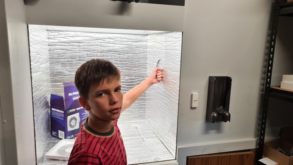


Last picture demonstrates current situation where 305 l/hr (Blauberg BRAVO 150mm White Low Profile Wall / Ceiling Exhaust Fan) fan is mounted together with the light switch being replaced with Fan Speed Controller.
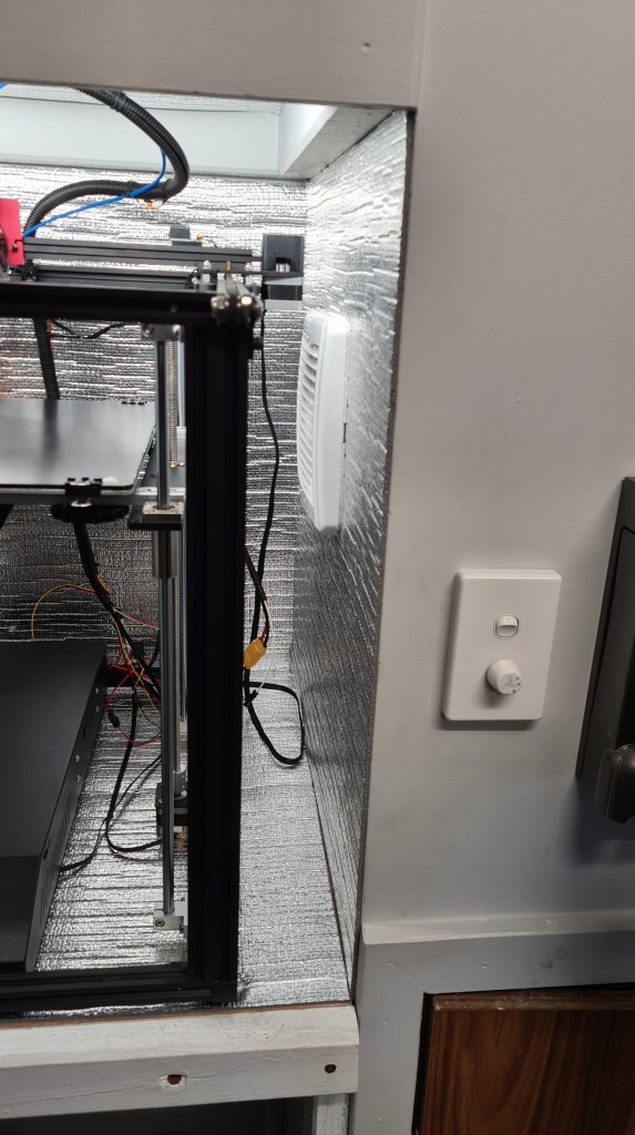
It looks awesome, on the lowest speed that fan is reasonably quiet and first prints show that it does excellent job. Fan’s exhaust goes straight into a cubicle where used to be a central vacuum cleaner with remaining exhaust to the roof. This is not connected, perhaps that would be another stage at the moment when we would start printing with something smelly (ABS).
I have to confess that I’ve been lately not contributing here as I would like to – mainly because I’ve hit several obstacles in our project and I didn’t want to report failure without having a solution in my hands. So – this is a story with a happy ending!
2-3 months back, our 3D printer started suddenly mysteriously malfunctioning. To provide you with some idea on this, see pictures below, but beware those are pretty creepy, so if you are afraid of rabbits missing ears, their heads being chopped off and missing body halves – don’t look! 😉

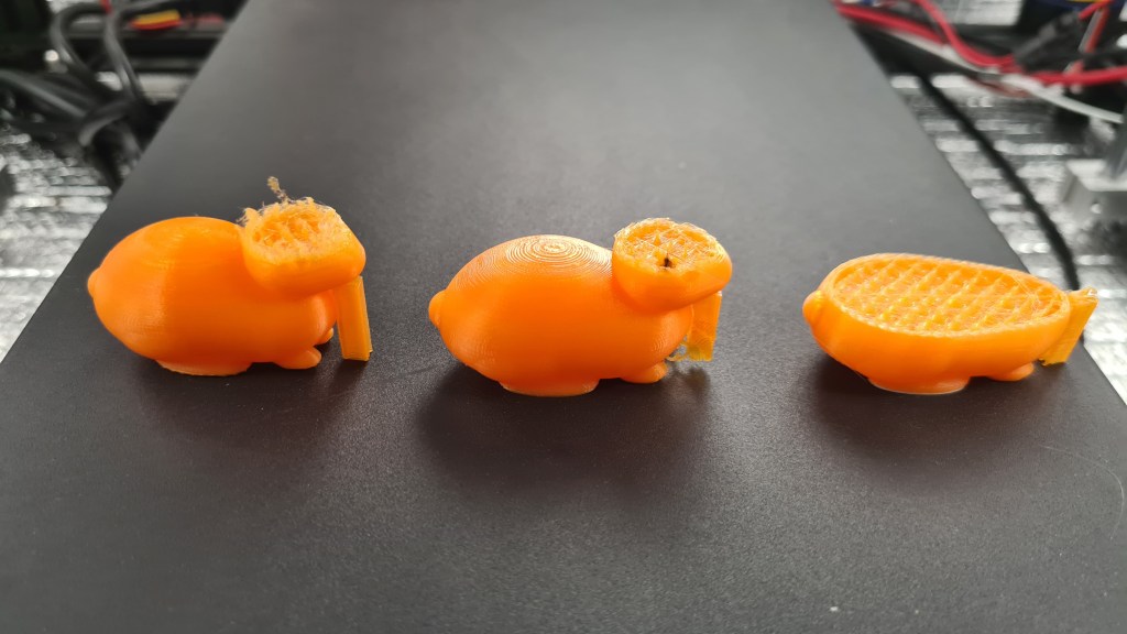

Yep – out of nowhere – all prints failed. Here comes brief list of things I did to find solution.
Following picture (borrowed from here) demonstrates that difference. The idea here is that with that bowden drive flexibility of filament and bowden somehow creates a problem in a nozzle, which leads into a clog.

It wasn’t cheap, but I was convinced to do anything!

Whole thing came in couple weeks and I started eagerly unpacking and mounting.
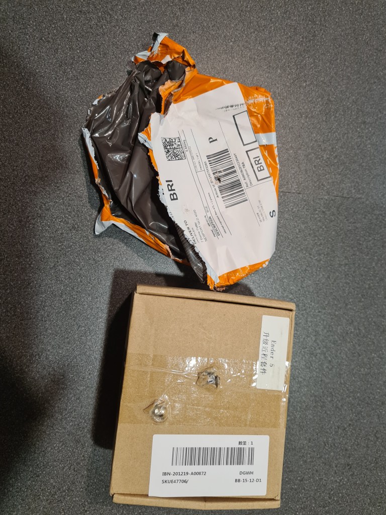
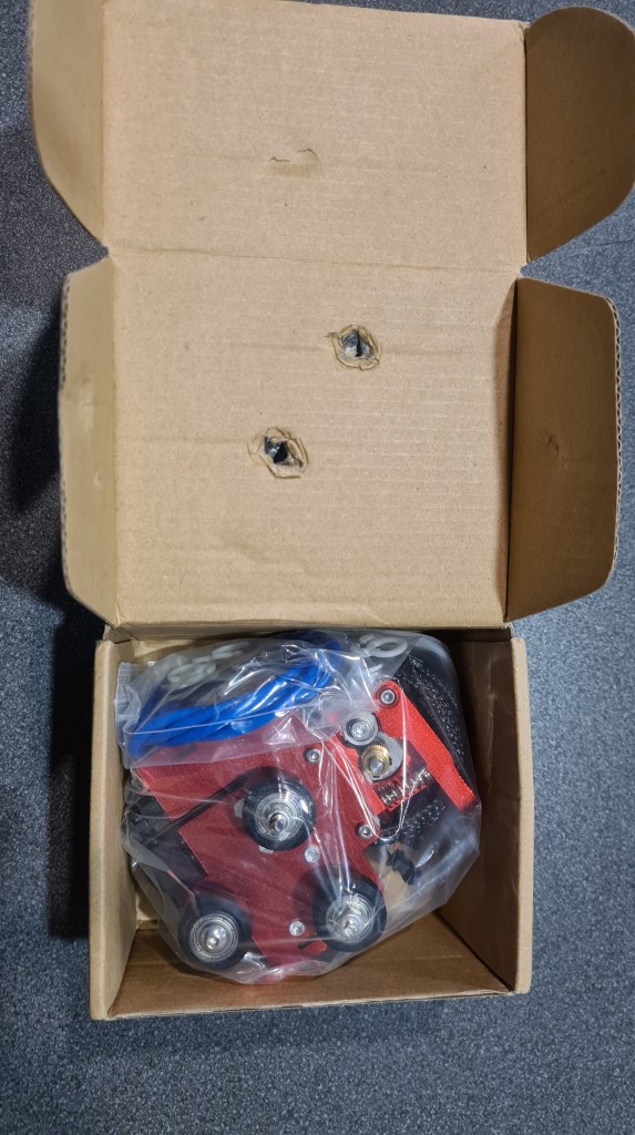
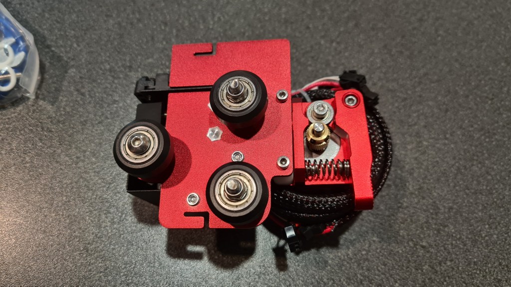
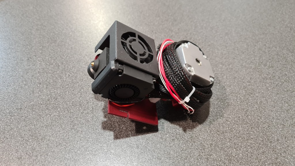

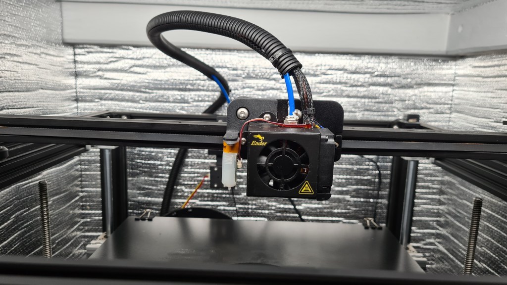

Whole operation took couple hours, but it was a real fun. Minutes later after taking that last picture I’ve been getting in a situation where I needed to Google to actually tell me how I feel – problem persisted – dead rabbits everywhere! Actually having all those crippled rabbit bodies, I made a Halloween scary-story about all that and played my boys a little bed-time story about how important is to eat carrot. Not sure about boys, but that cheered me up a bit.
Banging my head like this for more then a month already – I reverted to the last resort option and reached to the original seller’s support. Support page seemed to be strangely non-responsive, but still there was an email from them in my mailbox next day already!

Couple calls + chain of emails + many pictures later – Al suggested that one of the problems could be mysterious “Heat creep”. I started reading all about it, from all the sources and while playing with some parameters + doing some test prints I noticed that fans cooling the nozzle are not running! Bit of review of all connections and stuff revealed that few months back a bit of melted filament ended up in between blades and fan wasn’t probably running since – quick fix turned into a major one when I accidentally hit already-rotating blades with a screwdriver and broke one of the blades. Couple hours/days later after the fan replacement I was eager to give it another go! … which suddenly worked out! Anyway another consequent print failed again. 😦
So a tiny recap of the situation – not printing for months, printer practically new, several expensive upgrades, multiple support calls and I had a single successful print out of … 20? Still revolving that “Heat creep” mantra in my head I kept failing, while I still had that single successful print. How come it worked out, when even an instantly following print failed?

Dear Holmes, … while cleaning that clogged nozzle after 10000x failed print … I’ve accidentally touched the light bar I mounted roughly 2-3 months back to see how those prints are going well … it was hot, not too much, but it was hotter than I expected. Can it be? I sort of remembered that I turned off light before for that print which worked out, because we’ve been going out.
Another test print with the light turned off revealed that it was not a coincidence and all started working like before. I am still feeling super-charged while writing this post and while it was again typical PEBCAK solution, I am happy we can progress on this field again!
The idea here is to send a balloon, but it would be worthless without any load. Thinking about this all for a while I came with a basket with flashing LED beacon. This device is planned to be hanging below the balloon, broadcasting a message in a Morse code and making it visible for some reasonable time .. hopefully hours.
Whole project has two parts – basket itself and electronics. Basket below is designed in a SCAD. Note sign “Sebik #3” – That is to commemorate Sebi’s 13th birthday and #3 stands for our 3rd balloon release.
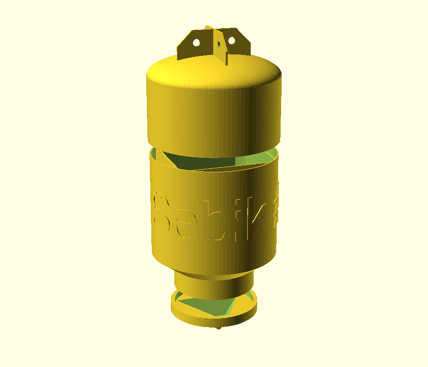
For reference I am adding OpenScad source as well (my WordPress keeps complaining that adding a .scad file is a security risk so it is here like it is – long). There is obviously quite a space for optimisation, but leaving it for next time.
use <ShortCuts.scad>
use <blimp_parts.scad>

$fn=100;

module Ear() {
    T(0,0,-170)
    Rx(-90)
    difference() {
        linear_extrude(height=3,center=true,convexity=0,twist=0,slices=10)
        minkowski() {
            polygon( points=[[0,0],[0,40],[30,40],[50,20],[50,0]]);
            circle(r=2);
        }
    T(25,25,0)
       cylinder(3, 5, 5, center = true);
    }
}

module InnerFrame() {
    difference() {
        Tz(4)
        scale([1,1,1.2])
        difference() {
            cube(140, center=true);
            scale([1,1,1.2])
            cube(136, center=true);
        }
        Tz(-90)
        tube(0, 0, 0, 180,  100, 100, 10);
        Tz(65)
        tube(0, 0, 0,  50, 120,  58, 30);
    }
}

module Bottom(){
    InnerFrame();
    Tz(60)
    difference() {
        tube(0, 0, 0,  30, 100,  58, 10);
        tube(0, 0, 0, 110,  56,  56, 10);
        Tz(-10)
        tube(0, 0, 0, 100, 100, 100, 10);
    }
    Tz(90)
    tube(0, 0, 0,  30,  58, 58,  2);
    Tz(-80)
    tube(0, 0, 0,  140,  90, 90, 2);
}

module TopSupport(){
     T(89,0,-116.8)
     scale([0.15,0.8,4.9])
     cube(15, center=true);
}

//Top
module Top() {
    TopSupport();
    Rz(90)
    TopSupport();
    Rz(180)
    TopSupport();
    Rz(-90)
    TopSupport();
    Tz(-150) {
      tube(0, 0, 0, 90, 92, 92, 2);
      Tz(60)
      tube(0, 0, 0, 10, 90, 90, 2);
      Tz(0)
      tube(0, 0, 0, 10, 88, 92, 2);
      scale([1,1,0.3])
      difference() {
        sphere(92);
        sphere(88);
        Tz(9)
        tube(0, 0, -1.3, 90, 92, 92, 92);
      }
    }
}

//Ears
module Ears() {
    Ear();
    Rz(90)Ear();
    Rz(180)Ear();
    Rz(270)Ear();
}

//Cap
module Cap(){
    tube(0,0, 106, 10, 64, 64, 6.2);
    Tz(115)
    cylinder(5, 64, 64, center = false);
    Tz(145)
    Rx(180)
    cylinder(30,25,60,$fn=3);
}

module CapHollow() {
    difference() {
        Cap();
        Tz(142)
        Rx(180)
        cylinder(30,25,60,$fn=3);
    }
}

module BlimpyText() {
    radius = 15.6;
    slices = 100;

    text_depth = 0.5;

    circumference = 2 * 3.14159 * radius;
    slice_width = circumference / slices;

    circular_text (slices, text_depth, slice_width, circumference, txt = "Sebik #3", height = 30, radius = 15);
}

Tz(-40) {
  Ears();
  Top();
}
Bottom();
Tz(20)
Rx(180)
scale([6,6,6])
BlimpyText();

Tz(40) {
  CapHollow();
}

module circular_text (slices, text_depth, slice_width, circumference, txt, height, radius) {
    union () {
        for (i = [0:1:slices]) {
            rotate ([0,0,i*(360/slices)]) translate ([0,-radius,0]) intersection () {
                translate ([-slice_width/2 - (i*slice_width) ,0 ,0]) rotate ([90,0,0])
                linear_extrude(text_depth, center = true, convexity = 10)
                text(txt);
                cube ([slice_width+0.1, text_depth+0.1, height], true);
            }
        }
    }
}
Now the electronics part – I had several sessions with Risa on this topic where he finally came up with following diagram:

What you are seeing there is bit bigger than what I thought so please concentrate just on that triplet – set of LEDs on the right side (and relevant cabling. Parts needed:

I suppose some brief description of what’s going on is needed:
Then we started having a fun with Sebi. First was just a blink test.
Meanwhile the tetrahedron-shaped beacon tip have been printed.


Followed by the main body.
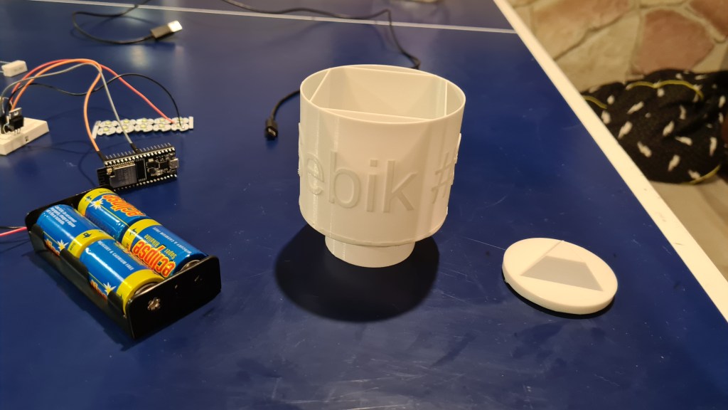
It comes together amazingly.

Ribs are in to provide better structural stability and also to have some platforms for hooking on internal devices at.

Meanwhile parts arrived, while I also bought set of Vera-boards to be able to solder these onto something.

Next was to drill holes in the beacon tip and install those LEDs. Final picture shows those also being glued in with a bit of silicone.

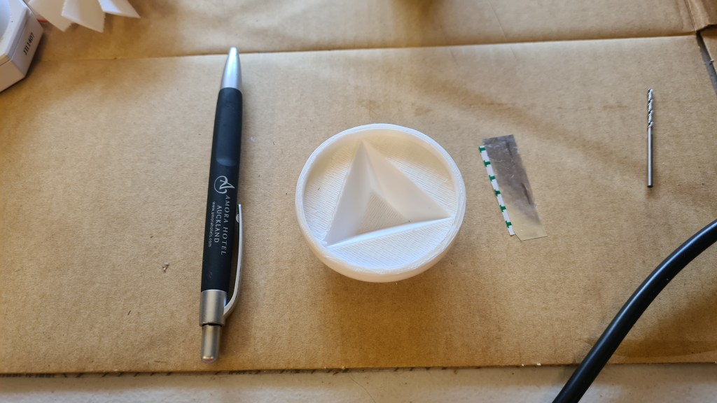
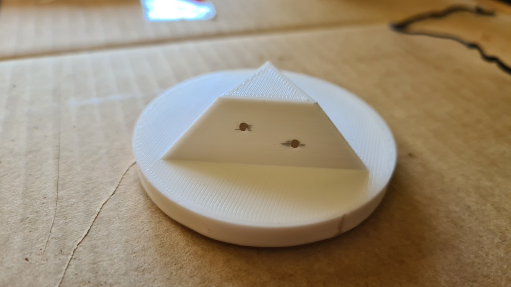
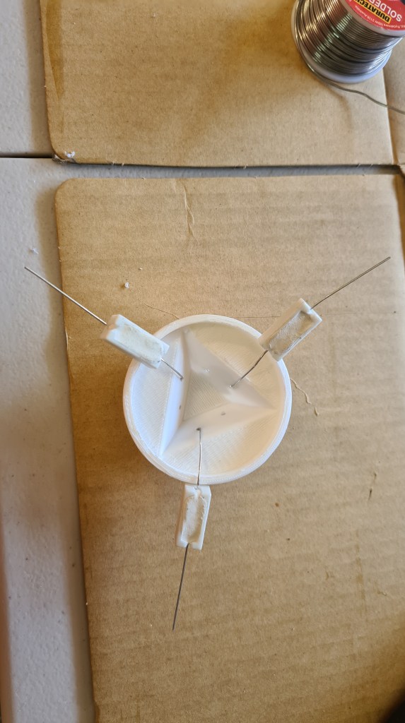

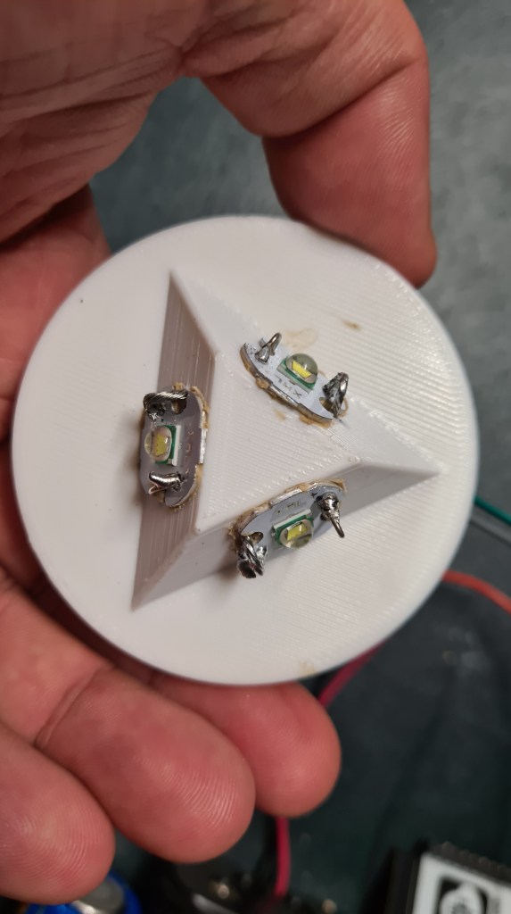
Meanwhile I really struggled with printing that Top part. It really took 3 attempts to do it properly and thanks to an advice from Andrew – the last one worked out as not being printed on a “raft”, but with a “skirt” option only. That finally allowed a separation between the print and scaffold.

Wiring went on and here is a Vera-board with all needed. Again it took me a while to get the proper technique about soldering on that Vera-board, but finally I’ve got it and I was reasonably happy with how that worked out. (Also Risa said that it is not too shabby 😉 )
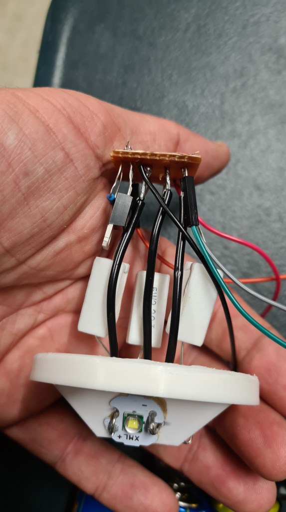
Time for some testing!
And how that would all work without a proper paint job 🙂 Sebi did a red main colour and Oli highlighted letters.


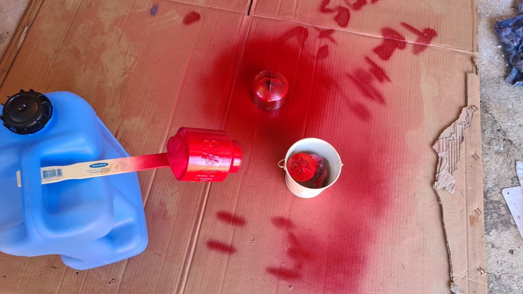
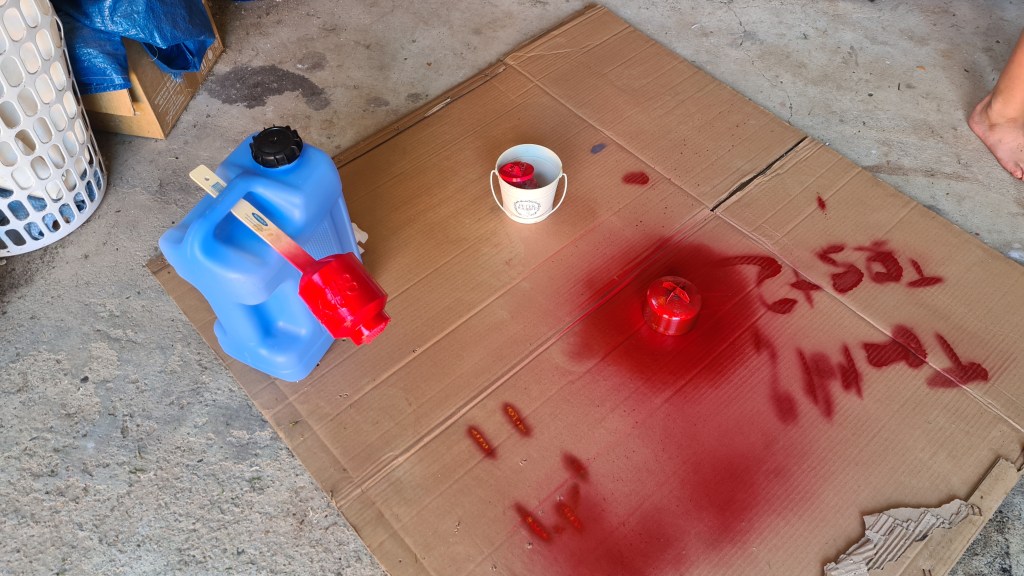
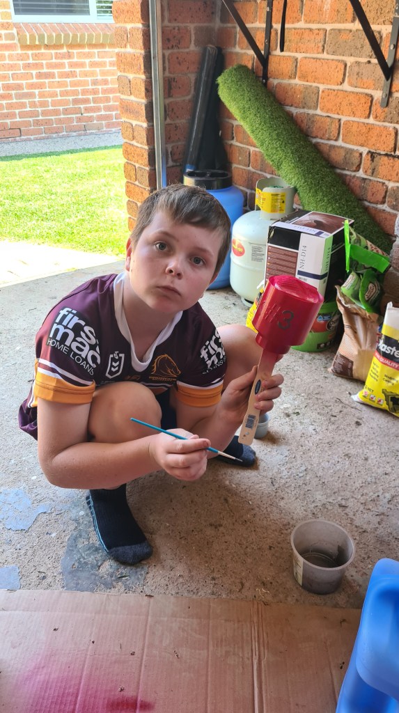
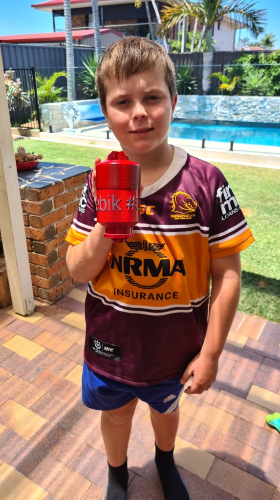
Not that bad at all, what you think?! 🙂
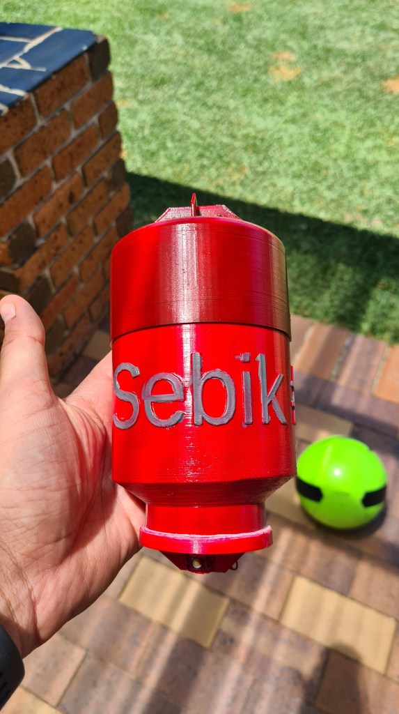
In preparation of the balloon release I saw how it doesn’t work well and started working on a plan B. Plan B is to buy a BIG canister of Hydrogen and fill the rest of the balloon with that.
Couple minutes of Googling came up with a BOC page offering high Purity Grade Hydrogen bottles. It asks you to create an account before being able to see the price – which came to my surprise – surprisingly high!

So I started reading about the Hydrogen compression – finding following quote somewhere where I can’t find a source anymore (apologies to the original author).
Compressed hydrogen must be stored in specially designed tanks capable of withstanding the storage pressures, which can range from 17 MPa to 70 MPa. These tanks are usually made of steel. However, tanks made of carbon fiber lined with aluminium, steel, or specific polymers are used when weight is a consideration. When compressed, the density of hydrogen at 35.0 MPa is about 23 kg/m3 and at 70.0 MPa is about 38 kg/m3. This leads to an energy density of 767 kWh/m3 (27 °C, 35 MPa).
It also came with following graph, which is surprisingly in [bars], while quote continues below.
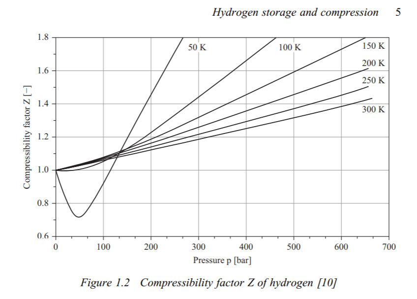
The volume of the storage tank is the biggest challenge, since the density of compressed hydrogen is lower than that of liquid hydrogen. Compression of hydrogen is an energy-intensive process which increases the overall cost. Estimates are about 6.0 kWh/kg for compression to 70 MPa, which leads to the CO2/kg of hydrogen stored to be high (approximately 1.3 kg of CO2/kg of hydrogen). However, compression only consumes a third of the energy that liquefaction does. In addition to the cost of compressing hydrogen, the cost of compressed storage tanks must also be taken into account. The cyclic loading of tanks, which tend to heat up as they are filled with compressed hydrogen, reduces tank life.
If you read through all that you can see that Hydrogen compression is quite a no-no in my shed-environment. I did a few calculations and I could potentially go with a 4m3 steel-enforced water tank which would be pressurised to 7 atmospheres – to be able to contain the same amount of Hydrogen as needed for our Phase 3 – 25m3.
13700KPa & 50L = 6m3
685KPa & 1000L = 6m3
Foreseeing quite intense family debate on this topic I went to the BOC page again and suddenly following offer appeared on a next page!
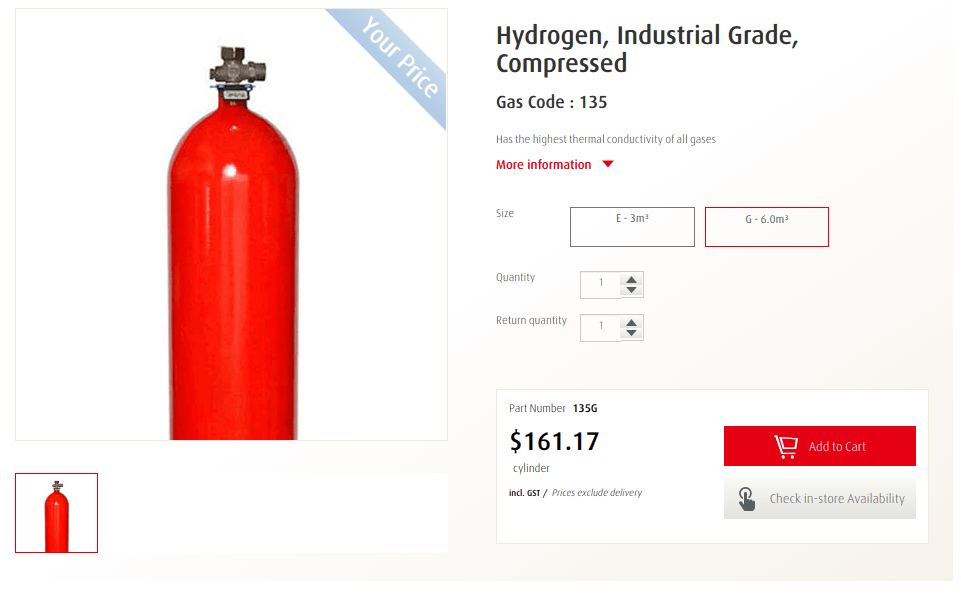
Grabbing Andrew (native language speaker) we walked in next day to the BOC store at Virginia and ordered one bottle. Invoice came with a bit different price (page stated that price is GST inclusive – BOC Virginia thought otherwise), but hey who wouldn’t sacrifice few dollars for a nice bottle of Hydrogen?
Interesting part about buying it came in the moment when the guy behind the bar asked if we have a gas trailer to carry it away, when I responded with confident “Of course… “. We’ve spent whole afternoon with Andrew trying to figure out what he actually meant with that and it wasn’t too positive – apparently it government wrote practically a book about dos and don’ts.
Asking Serge about an advice calmed me down – Serge was able to carry all his welding bottles in a car and while that was more then a few years ago I took it with a gentle disclaimer and kept asking. At the end Rob saved me!
This is a story of Rob Mataic!

I gave a call to Rob on Friday morning, 10 minutes later he picked me up in Sandgate with his Ute, carried me to BOC Virginia, helped me to retrieve the bottle, tied it on his Ute deck and carried it back to my house – quite surprising Veronika with his sudden appearance.
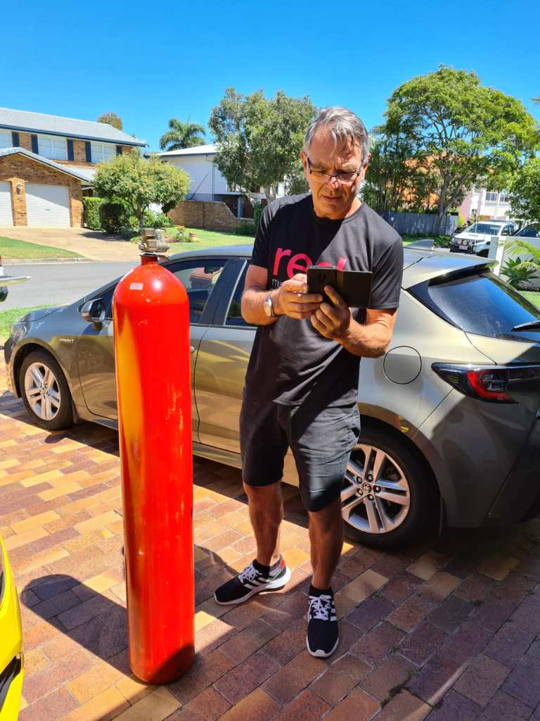
Huge thanks Rob I owe you another one now!
I asked Rob to take a picture of that outlet so i can get a pipe for filling the balloon.
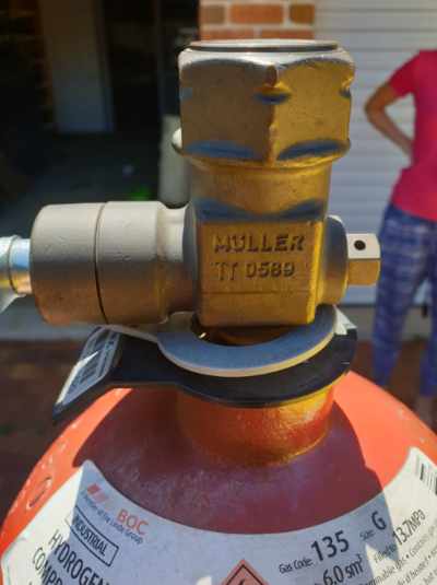

Well, instantly couple of obvious problems appeared.
1/ how to release that Hydrogen from something what is pressurised to 137+ atmospheres (13.7MPa) (Did you know that Venus surface pressure is ~90 atmospheres?)
2/ How to store that “bomb” securely in a house full of kids.
I’ve learned a lot about high pressure bottles and it is quite a topic. Long story short this Hydrogen bottle comes with AS 2473 Type 20 outlet connection. Good reading here, but long story short Type 20 is same as Type 10 (typical Helium outlet), with opposite threading.
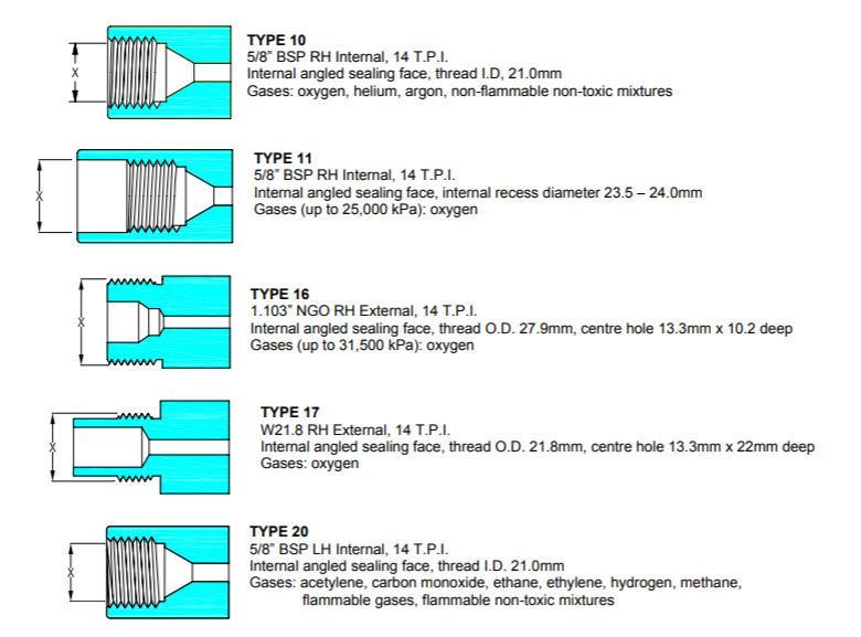
Asking all around I was strongly recommended to use a pressure regulator, unless seeing our house levelled to the ground. So checking with Google, it came with following Harris 825 Hydrogen Pressure Regulator, Vertical Inlet, Stainless Dia, 0-1000kpa – for quite bitter $338 AUD.

Some options came around and offers came down to $250 AUD, but still much more above my ten-bucks budget I was thinking of. I’ve parked this one as being an overkill for this situation. This however led straight to the problem 2/ safe storage.

Getting inspiration from “Transporting dangerous goods in Queensland” document – I’ve picked a place in a corner of our garage, where it is well ventilated and can be safely attached to the wall.
It took just few minutes of a virtuous work with a drill and all looks pretty good!

Our bottle will stay there safe till we’ll have a good use for it. I suppose that Hydrogen has to validity date so we are not in hurry now and we now have a high quality hydrogen for the stage when we’ll start experimenting with a fuel cells.

I’ve lately ended up with my whole head buzzing with ideas and plans. It actually became quite annoying when I realised that by adding some new one I am loosing another one.
Quite interestingly the article “This Is How Many Tasks Your Brain Is Processing Right Now” claims that human brain can process up to 50 tasks in parallel – well, clearly not mine (or I am some lesser form of human)!
From realisation that there is my weakness I moved to take an action on that and got inspired by a road map for a nice & lovely PC tycoon game from Jan Zelezny – Mashinky on a platform called Trello.
Few minutes later my own road map came to life. Enjoy! 🙂