Beacon preparations

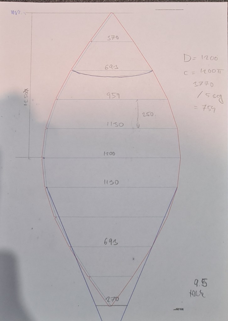
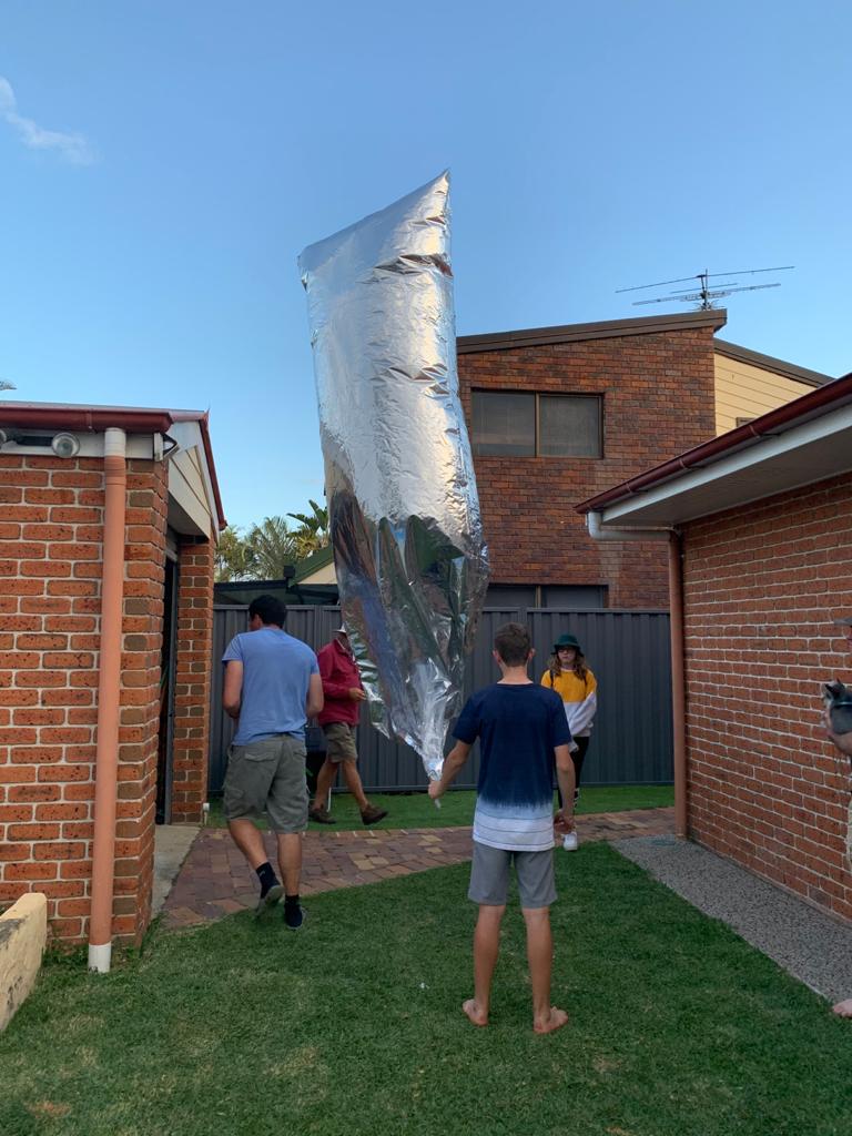
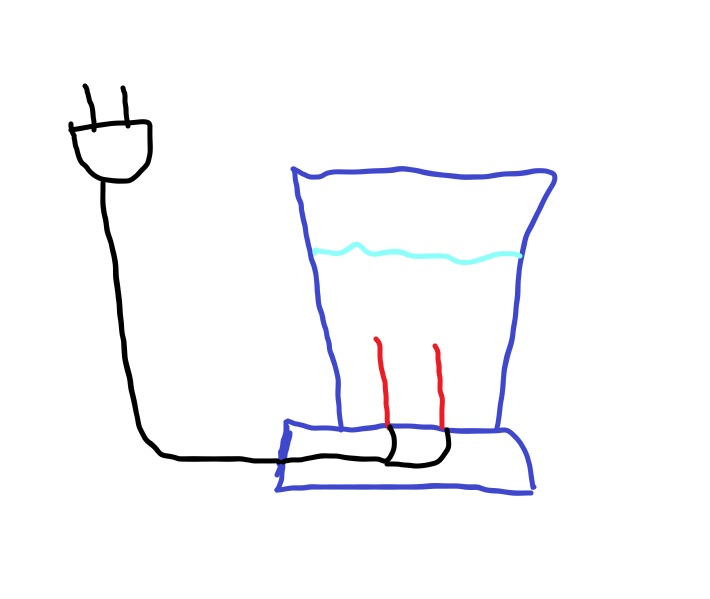
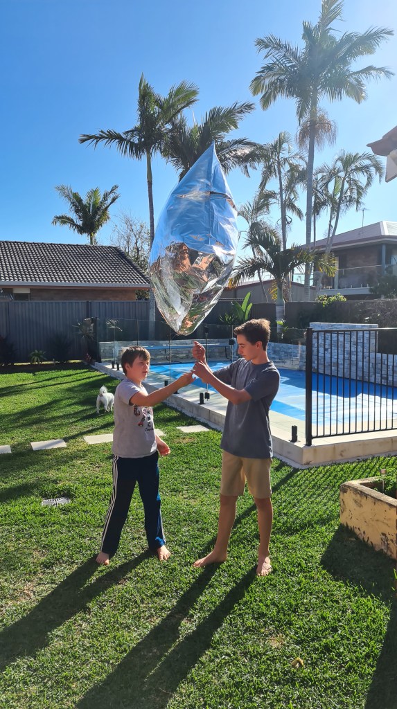
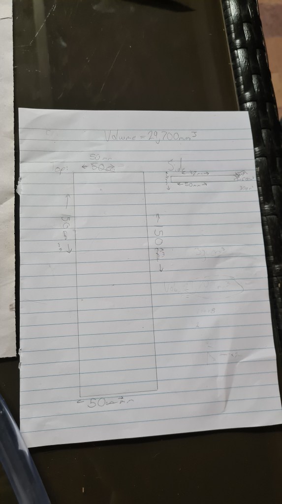
The idea here is to send our next balloon with a hanging beacon. Beacon to repeatedly keep sending out a Morse-code encoded message (currently thinking about some Chuck Norris jokes). I’ve covered my rough plan on a picture below.

LEDs to be organised in a triangular or pyramid shape, covering surrounding area and facing 45 degrees down. I’ve discussed this with Risa and he came with a plan. It first came with an order of some super-powerful LEDs to do the job properly – Model Type: Cree XML-T6.

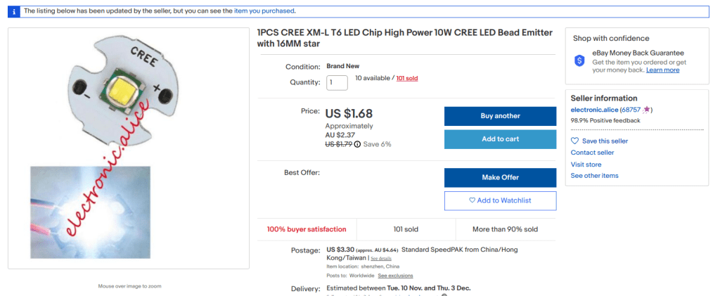
Technical Parameters
DC Forward Voltage (VF): 2.9-4Vdc
DC Forward Current (IF): 3.0A
Low thermal resistance: 2.5ยฐC/W
Maximum junction temperature: 150C
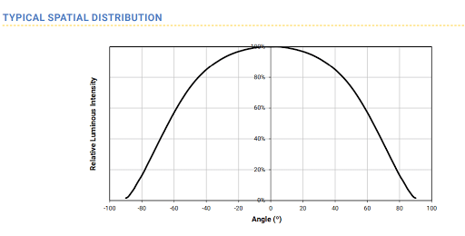
Viewing angle: 125ยฐ
ANSI-compatible chromaticity bins
Unlimited floor life at <30C/85% RH
Reflow solderable-JEDES J-STD-020C
Electrically neutral thermal path
Emitted Color :White
Color Temperature: 6500-7000K
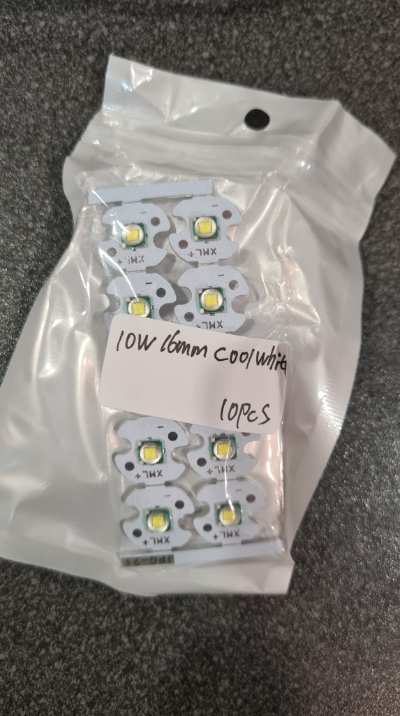
Power: 10W
Diameter : 16mm

Ordered 10 of them and those came a week later.

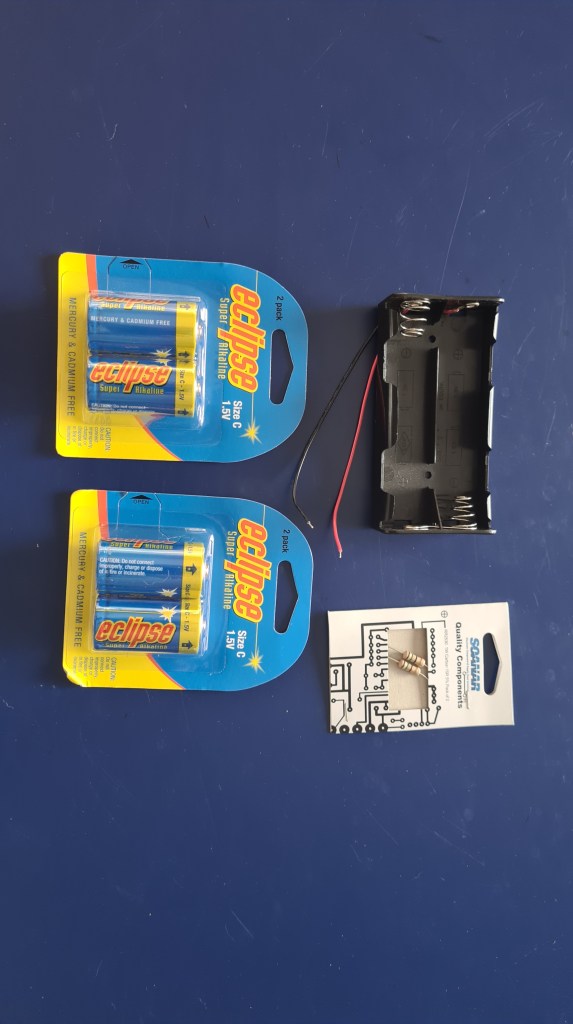
Being eager to test those, Risa provided wiring instructions + list of components needed to bring it to live.

So in the above diagram Ra should will be new 15 ohm resistor and Rb our new CREE LED. Vin is a 6 volt battery. This will allow 200 milliamps to flow through the LED and the heat dissipated will be roughly 600 miliWatts.

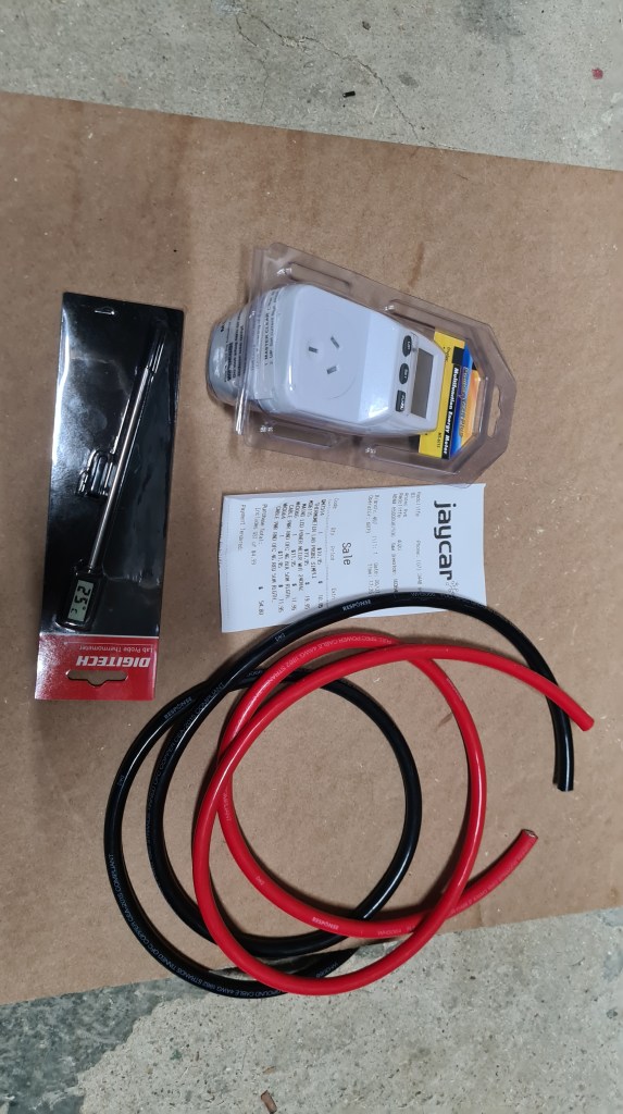
Another quick visit to JayCar and we had all needed.

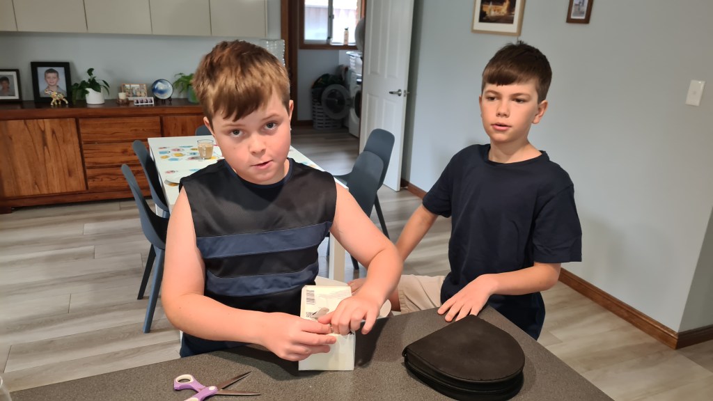
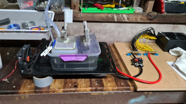
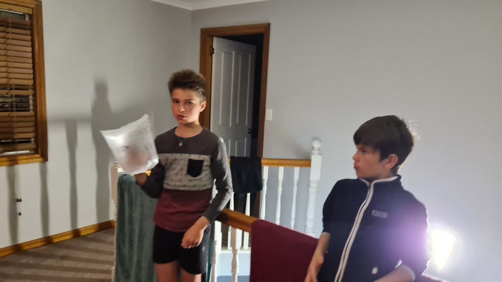
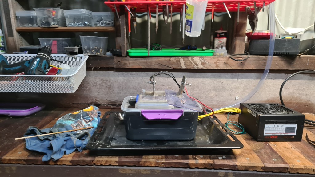
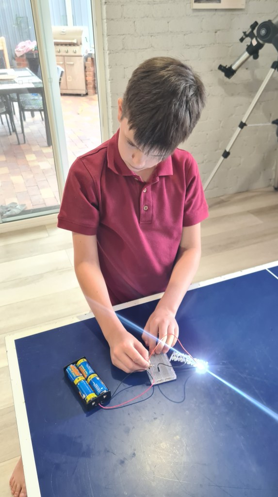
Sebi wired all components together though his bread-board and everything worked out practically out of the box.

Pretty bright – and this is far from 100% output

Risa then asked Sebi to write an application which would send a signal to any pin he choose for 100ms on then off for 3sec. Sebi commented this as a “piece of cake” and had it done in next 10 minutes (including demonstration).

const int output = 3;
void setup() {
pinMode(output, OUTPUT);
}

void loop() {
digitalWrite(output, LOW);
delay(100);
digitalWrite(output, HIGH);
delay(3000);
}

I’ve captured that on a short video below.

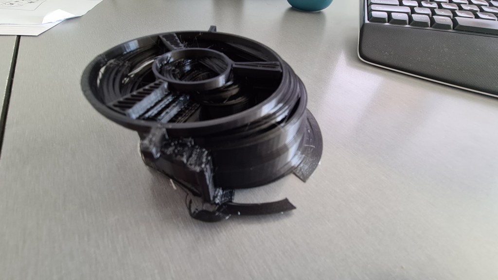
Next stage will be to design a proper holder for a set of LEDs, calculate power consumption and also Sebi to write our Chunojomor – (Chuck-Norris-joke-Morse-translator).

Legs of steel: Norris is shown in a spoof online video straddling the wings of two passenger planes with a human Christmas tree of skydivers balanced on his head

Aluminium corrosion

This actually is a story good ending, but let’s start from beginning.

Having balloon glued and ready I couldn’t resist and started with its filling. First step was to prepare a new electrolyte and I have to say that it really feels good to have practically unlimited supply of KOH now.

Adding water to ~2kg of KOH we’ve witnessed a beautiful exothermic reaction again reaching and measuring it with our thermometer we’ve been able to get values even over 120C. Beautiful.

Next stage was to use Veronika’s vacuum cleaner to deflate our balloon. Sebi happily took care of that.

Finally we could kick of hydrogen production and balloon filling again.

Everything went beautifully and I’ve been able to do first 4,5 hrs run without any problems. All functioning beautifully – generator, cooling pump and balloon – ballooning.

That was two days back. Yesterday I came back to start another session and when turning on the generator I’ve noticed some sort of smoke coming out of it, however that was too early as electrolyte wasn’t hot enough to generate any steam. Having a closer look it came to me that I was terribly wrong and worries I had weeks ago about that aluminium lid materialised.

Apparently Aluminium is generally quite sensitive to number of corrosive effects – Atmospheric, Galvanic, Pitting, Crevice, Intergranular, Exfoliation, General, Deposition, Stress corrosion cracking, Erosion corrosion, Corrosion fatigue, Filiform corrosion and Microbiological induced corrosion. Good reading on all of those for example here.

Interestingly the picture above actually show how is aluminium actually doing pretty good job of resisting corrosion. The thin coating of aluminium oxide forms a protective shield that inhibits further corrosion. However, salts are extremely corrosive and our generator causes this film to worn out. Apparently thereโ€™s an easy way to protect aluminium from salt water and prevent unsightly corrosion – a powder coating, but it is too late for our lid here.

I also took a video, where it perfectly demonstrate how is that aluminium being eaten away.

Well, that was quite a drawback in our project and pretty much ruined my evening. Feeling quite down about it I shared pictures and video with Serge & Vlada and Serge instantly offered his help with replacing our aluminium lid with a new one made of formica.

Just a tiny quote from Wikipedia: Formica is pretty much also know as bakelite and was invented in 1912 by Daniel J. O’Conor and Herbert A. Faber, while they were working at Westinghouse, resulting in a patent filing on 1 February 1913.

Serge came precisely 19hrs later since reporting the problem and started cutting and drilling a new lid for me.

I’ve been almost feeling silly when Serge did everything on his own – like a live Robot.

No longer then 30 minutes, all setup was back in action and looked splendid!

Thank you Serge, you saved my day again!

Balloon Mk. I

In preparation of the “cigar” shape we prepared our tiny sphere project. Now the time has come to put few things together (Mylar gluing & 3D Printing) and try to build something big again.

Starting with a draft we needed to find out how it will fit to our 1200mm Mylar sheet. So I’ve picked that we’ll go with sort of 5 segments and calculated some guideline values to be able to transpose those to a cutting plan.

I’ve been feeling sorry about a waste so came with a cunning plan to fit in more. Hope that picture below will be self-describing.

That all came with ~3m3 volume, so I gave a call to Serge to give me a hand with some measuring & cutting – as always, Serge appeared same day and started helping me instantly. ๐Ÿ™‚

We’ve carefully measured a 1/2 template from a carton paper and then used it to draw it on a Mylar.

Situation changed when I finished our current Mylar roll and started with the “new” one. It came to my surprise that it wasn’t actually Mylar on its own but one side Mylar and second rubber! It was significantly heavier, but also stronger. Such a Mylar sheet came with a 220 grams of weight. That meant that 5 sheets would eat out 1kg of our lifting force.

Handling a panic attack I decided that we’ll add one more sheet – making it 6 in a total. Coming back to a calculator, that grown balloon’s volume to 5+m3, making it just a bit bigger then what I thought, but hey!

Sebi helped a lot with cutting

And couple hours later we had all sheets ready! (2 silver + 4 black ones)

Meanwhile, when working on the balloon itself, I fond out that some sort of gas filling / releasing valve will be needed and started designing one in OpenSCAD.

Finding a right way to make the printer to actually print it, took couple weeks, but result is simply awesome!

On a paper and printed result assembled
In pieces

Next stage was to glue everything together. Picture below shows a stage where I just finished gluing all 6 slide sides together. This all was quite a story as I’ve run out of Mylar and the new Mylar, which I ordered in advance, came to my surprise with being double sided – rubber & Mylar. Obviously it all came much heavier then what I was initially counting for. Weighting one sheet, it came with 220 grams. That is 4 times more than the original Mylar I’ve been using.

Quick thought came and I’ve decided to add another segment to the balloon extending from 5 to 6. Recalculating our new balloon volume I came to a new value of ~6m3, what is quite a surprising difference to 3m3 with just one segment less which was 3m3. Another proof that humans can’t understand exponential growth.

Flipping whole setting inside out and adding a cap was another interesting task, while we’ve ended up with a nice folded balloon.

We’ve moved to another stage where we started with pressure tests.

Some of those parts, which I was worried about, were unfortunately not good enough, so I asked Serge again to give me a hand on this. Serge suggested to use a Mylar tape to re-cover balloon seems – Ametalin!

I bought one in Bunnings and asked Serge to show me his mastery in its usage.

It took us couple hours to go through all seems, but it was worth it.

We had a QA supervisor to make sure that all works are done in a safe and pet-friendly environment. ๐Ÿ™‚

Last part was to install our new valve and all is now ready to go with another Hydrogen filling attempt!

Thank you Serge again and let’s move on to another stage of our project!

How to glue Mylar

I’ve been for more then a month wondering on how to properly join Mylar sheets together. The first attempt with Blimpy was practically a failure as it was leaking like a colander and it was a serious relief when that balloon (so so) flown away.

To prevent this I’ve discussed this with Vlada and he suggested a heat impulse welder or classical iron. Long story short it was a setback after setback. Mylar has a melting temperature starting around 250C and cotton ironing is around 205C. Even pushing Veronika’s iron to the max – Mylar was still happy – in sheets.

So I went to gumtree and bought a “hair straightener” – same result. Mylar simply didn’t get what I want it to do! Full of disappointment I came with a destructive idea and tried welding it with a soldering pipe – and it was holding!

However it also came with so many holes that whole procedure sort of lost its purpose. I’ve kept exploring and thought of some sort of RC model covering iron like this below, but it apparently won’t go over 220C.

Turnigy LED Covering Iron 240V (UK Plug)

At the end I came back to Serge and asked him for another advice and … it was working! Serge suggested to use a simple adhesive cement (like I did before), but use a can instead of spray to better control thickness of the glue layer.

Critical part is where you need glue both parts and patiently wait till they are no longer “touchy”. Even 5+ minutes. What a surprise … when those touch they instantly stick together and form excellent joint!

I did a stress test and couldn’t believe how strong it is, so I gave it to Sebi to have a go as well.

It passed our Q&A! Now we know how to make very strong sews and that being in hurry may not be always the best. Thank you again Serge! ๐Ÿ™‚

We have a 3D printer!

Veronika somehow realised that the only missing thing to complement our manufacturing ability is the 3D printer. After a brief discussion I’ve picked “Creality Ender 5 Plus”, which is a Large Format Core XY Style 3D Printer with 350x350x400mm Build Volume for ~$1000 AUD.

This should be one of the largest volume “public” printer available, where common printers work mostly with a volume more lie 250x250x400mm.

Box came in couple days from Sydney and Sebi & Oli helped me with its assembly.

Printer also came with a single 200g white PLA filament. If you wonder what 3D printing filament and PLA stands for, I recommend very nice article on Wikipedia.

PLA has become a popular material due to it being economically produced from renewable resources. In 2010, PLA had the second highest consumption volume of any bioplastic of the world, although it is still not a commodity polymer. Its widespread application has been hindered by numerous physical and processing shortcomings. PLA is the most widely used plastic filament material in 3D printing.

Wikipedia

Traditional question appeared – “Where to put it”? Luckily there is some sort of unused wardrobe in our garage so I came with a plan to expand it to be to some serious use from now on. I’ve documented that on few pictures below.

We couldn’t resist to kick of some printing and picked one from those pre-loaded models.

30 minutes later … Tuzi is a rabbit! ๐Ÿ™‚

When working, it really looks pretty sci-fy (or neardy ๐Ÿ˜‰ ).

Since that we’ve been productive!

Second print was a rock-guitar for Jakub K.

I did some experiments and printed ducted fan. (It actually came out awesome for such a complex print!)

Sebi designed and printed missing bishop.

Straight from print
After some tiny cleaning

But not everything went that awesome and I had number of bad prints as well.

I am not 100% sure, but this above was really one very difficult one and I suspect that nozzle hit the print as the room temperature was dropping quickly on a windy day and printer was shrinking (its made from aluminium).

I am now preparing a plan on how to address this issue through a proper layer of the thermal insulation + front door. However I suppose it will take me a little to get it ready, while other things are happening meanwhile! ๐Ÿ™‚

Update 12 Oct 2020

I think that all those failures are a combination of several factors, the main one seems a calibration of the printer to be done always before the printing.

Hydrogen generator Mk. VI

After the great success with our second balloon release, I noticed several potential problems with our current generator design.
– the Perspex lid is changing its shape substantially
– electrolyte’s colour is impenetrable black-brown soup
– hydrogen-part container seems to be leaky around the electrode
– the “bubbler” is wobbly and potentially leaky as well

So, reminding Kieran’s advice on KOH being environmentally ok, I’ve got rid of current electrolyte. I have removed bubbler and replaced exhaust from the hydrogen container with a screw-on-garden-hose outlet. Sealed all gaps between lid and electrode with new amount of paste, and covered it with rubber.

However the large lid replacement needed more thinking. After a brief consultation with Vilem I bought a 300×600 aluminium sheet at Bunnings for $45.30.

Now I just need to cut those holes in there again! Receiving following picture of Serge having good time at Morreton Island I came with a cunning plan.

While asking Serge how he would cut those holes I was actually hoping to get him to show me some of his secret shipwright techniques. Serge didn’t fail me and appeared just couple hours later with all the tools and practically instantly started cutting.

Few minutes of an incredible noise and Serge became a new Iron Man!

Robin came as well (it’s been her birthday! Happy birthday Robin again!!) and took few pictures – so there is one with me being on a health & safety duty.

Result was just awesome – once you know how to do it, it all looks so easy.

My vs. Serge’s

Now, it took me about a week to get back and start putting things together again.

that “bubbler” … is my wine glass

Looking at it I decided to give it a bit of “Tesla” style.

And voila!

… glass is empty ๐Ÿ™‚

I feel so good about it! And huge thanks to Serge & Robin – it wouldn’t look so awesome like this if you wouldn’t come. XXX! ๐Ÿ™‚

Now when it is all ready … we need to start with that balloon again. Stay tuned!

Hindenburg disaster – now in colours

Ok, this time it is something different. While browsing through all the corners of the Internet, I came to a Czech article about an interesting technology called – DeOldify. Surprisingly Vlada keeps spamming whole family with number of coloured pictures from our family albums. That all triggered my interest so I started reading more.

So I suppose that it clear – DeOldify is a technology which allows colorization of black and white images and it do so for videos as well. This technology is using pre-trained neuron network to do this job and its results are fascinating! Let’s start with something close to Down Under – hereโ€™s a colorization of the last known Tasmanian Tiger, which went extinct in 1936.

I couldn’t resist and did some pictures on my own – How about few black and white pictures from our previous article about Piasecki PA-97?

Original
Coloured

And it works for artistic pictures as well!

Original
Coloured

I’ve almost forgot – here comes the Hindenburg Disaster – now in colours!

If you are interested in having a go – give it try! Just go to following website and upload your picture and see results instantly. Of course, let me know, if you’ll end up with some interesting results and I’ll share those here to make this article even more interesting. ๐Ÿ™‚

Here are few “best of” from Vlada:

Piasecki PA-97

I’ve been introduced to Piasecki PA-97 few weeks back when looking for some interesting blimp concepts. PA-97 is the Helistat – a hybrid airship/helicopter, designed for heavy vertical lift.

The PA-97 was built under a 1980 U.S. Navy contract for the Forest Service to demonstrate a heavy vertical airlifter for harvesting timber from inaccessible terrain. The single demonstrator used a retired Navy ZPG-2W blimp envelope and four Sikorsky H-34J helicopters. The combination of a large blimp with powered lift made the 343 foot (104.57 m) long helistat the largest dynamic lift aircraft in the world.

Wikipedia on Piasecki PA-97

This monster project kicked off in 1980 and cost $40 million. Like you can see on the picture below, its prototype looked adventurous on a first sight.

Well, things didn’t go well at all when the PA-97 crashed immediately after liftoff on a first test flight, killing one of its pilots.

There are few things about PA-97 project to learn from:
– Using Helium, as a lifting gas, won’t help you when you are also using helicopters
– It is possible to convince your government to invest $40 million into idea like this
– There are apparently more crazier people on this planet than what I thought ๐Ÿ˜‰

OpenSCAD

Discussing the blimp design with Andrew, he came to me with so far unknown tool – OpenSCAD. I’ll quote Wikipedia to introduce it a bit:

OpenSCADย is aย free softwareย application for creating solid 3D CAD (computer-aided design) objects. It is a script-only based modeller that uses its own description language; parts can be previewed, but cannot be interactively selected or modified by mouse in the 3D view. An OpenSCAD script specifies geometric primitives (such as spheres, boxes, cylinders, etc.) and defines how they are modified and combined (for instance by intersection, difference, envelope combination andย Minkowski sums) to render aย 3D model. As such, the program doesย constructive solid geometryย (CSG). OpenSCAD is available forย Windows,ย Linuxย andย OS X.

And you know what? It instantly made my brain spinning. I started playing with that on the same day and all my basics from AutoCad + Blender came finally to some use here.

Same late evening … an EDF unit came up.

While the above may look like some super-sophisticated mechanical part rendering – achieving this with the OpenSCAD is pretty simple. Actually 40-liner.

use <ShortCuts.scad>
use <Naca4.scad>

module TubeSimple(h, r1, r2, t) {
    difference(){
        cylinder(h, r1, r2, center = false);
        cylinder(h, r1 = r1 - t, r2 = r2 - t, center = false);
    }
}

module edf(){
    Ry(90){
        //back ege
        Tz(4)
        TubeSimple(0.2, 4, 3.9, 0.2);
        
        //main body
        Tz(-1)
        TubeSimple(5, 4, 4, 0.2);

        //front inlet
        Tz(-3)
        TubeSimple(2, 5, 4, 0.2);
     
        //rotor
        Tz(-2) {
            sphere(1);
            cylinder(h = 6, r1 = 1, r2 = 1, center = false);
        }
        Tz(4)
        cylinder(h = 2, r1 = 1, r2 = 0, center = false);
    }
    
    //Propeller
    n=12;
    for(w=[0:360/n:359])
    Rx(w)
    proprep(tip_scale=1, L = 2, r = 3.6, twist=-30, rot=-20, naca = 1408);
}

Now, how difficult it would be putting together our Blimp?! So couple more nights later …

This time is code bit longer, so adding just the main part for its illustration.

use <ShortCuts.scad>
use <Naca4.scad>
use <blimp_parts.scad>

$fn=30;

Rx(90) {
    // Main body
    %body(5);

    //EDFs
    color("DimGray") {
        edf_custom(-7,0,-16, 270);
        edf_custom( 7,0,-16, 270);
    }

    //Inner support
    color("SandyBrown")
    inner_support();

    //Tube Left + nozzle
    tube(-7,0,-16, 50, 1, 1, 0.01);
    tube(-7,0, 34, 3, 1, 0.6, 0.01);

    //Tube Right + nozzle
    tube(7,0,-16, 50, 1, 1, 0.01);
    tube(7,0, 34, 3, 1, 0.6, 0.01);

    //Controls
    color("Silver"){
        rudder(14,0,15,180);
        rudder(-14,0,15,0);
        rudder(-7,7,15,270);
        rudder(7,7,15,270);
    }

    //gondola
    gondola_skelet(0,-9.2, 0);
}

Let’s move on! OpenSCAD can export its models in STL format, making things even more interesting.

STLย (an abbreviation of “stereolithography“) is aย file formatย native to theย stereolithographyCADย software created byย 3D Systems.ย STL has severalย backronymsย such as “Standard Triangle Language” and “Standardย Tessellationย Language”.ย This file format is supported by many other software packages; it is widely used forย rapid prototyping,ย 3D printingย andย computer-aided manufacturing.ย STL files describe only the surface geometry of a three-dimensional object without any representation of color, texture or other common CAD model attributes. The STL format specifies bothย ASCIIย andย binaryย representations. Binary files are more common, since they are more compact.

At this stage I’ve exported our current Blimp model as the STL file and apparently there are some clever WordPress plugins to view it in “3D”, however my licence doesn’t allow me to install those and I don’t want to upgrade yet. So if you are interested, here is DYI:

  • Download the model through this link
  • Go to ViewStl website
  • … and use instructions there to get it going ๐Ÿ™‚
Enjoy!

… now I just need some VERY BIG 3D printer! ๐Ÿ™‚

How to glue a … sphere

In preparation of our new development, I bought new 50m sheet of Mylar from a shop near Gold Coast. That happened on 1st Sept 2020 and it’s been in a truck for today’s delivery since 4th Sept 2020. That now makes 13 days (today is 13th Sept, still 2020). I hope that that truck driver has some good fun with that ๐Ÿ˜‰

Meanwhile I’ve been thinking on how we are going to glue all that stuff together this time and came with a asking Mr. Google for some clues. It came with this fantastic page TemplateMaker.nl.

Don’t forget to buy this guy a coffee!

Well, so where to start – now I need to prove that it is possible to glue 3m3 sphere-ish shape balloon where it can hold Hydrogen longer then I can produce that. With 1,2m wide Mylar sheet we need to some simple calculations. I helped myself with CalculatorSoup.

As per above, we need to look for some sort of 5.6m circumference. 5.6 / 1.2 -> 5 sheets. Let’s do it!

Using the template maker I’ve printed out a sphere template with 5 segments and got entertainment for a whole family to cut it out.

Bit of patience and art with a paper glue and … voila!

That was easy, wasn’t it? Now just to come up with the most efficient cutting template for our Mylar sheet.

Release the Blimper!

Seeing how that new balloon leaks – I had no patience to fix it properly so I decided to get rid of it and start from a scratch. However it wasn’t leaking enough not to have some fun with that!

Started on Friday late afternoon, through Saturday and most of Sunday – I’ve been able to fill it enough to call it a day and stand to my plan.

Saturday morning
Sunday afternoon

Meeting our Redcliffe gang for Sunday coffee – I’ve announced a great balloon release. The deal was that balloon will be released to be heading inland not to cause any additional pollution to the sea and winds were good 4pm-7pm.

All came to support it and made a great atmosphere! Kids wrote their messages to be carried out in a bottle.

Some messages were … secret!

Even our girls were happy that boys are having fun.

First moments out of hanger …

I couldn’t resist and asked Timo to take a picture of that historic-moment.

Yes – Lucas will be remembered like this .. forever. ๐Ÿ˜›

Very first moment when balloon got released.

And now it’s on its way to “here be dragons” land.

We’ve been seeing it going for another 15-20 minutes and I think it was awesome! All were having great fun and I felt relieved that it worked out so nicely. Thank you all once again for coming and all your support!

Now I have empty shed to move to phase 2.5, stay tuned! ๐Ÿ˜€

KOH restocking

After all those cooing and power upgrades we finally mover to filling in our second balloon (“Blimper”). Now i am running the Hydrogen production for 8+ hrs without any interruptions and it came with a new challenge – evaporation! It looks like we are loosing quite a significant amount of electrolyte through every session.

Thinking economically – the solution needed is roughly 25%-30% and that makes 2kg of KOH for our 6l basin. I was so far buying 1kg for $18AUD, Looking for some more efficient option I’ve contacted “Santo Australia Cleaning Products” where they offer 25kg bag of KOH for $75AUD.

I’ve arranged our Friday lunch with Keith to pick it up.

Bought a 25l saleable keg from Bunnings.

Got couple of child-slaves to transport it to our shed.

Took a picture before…

… and after.

I shouldn’t be running out of KOH for another year! ๐Ÿ˜€

Cabling upgrade

Having a new welder in and doing great I’ve become bit picky about all that setup, seeing those welding clamps being as the weakest part of all.

I think that on the picture above it is clear that contact surface between those clamps and bolts is the weakest point. So I started thinking if I can replace all that stuff with something what would look more “industrial”.

My research started (and ended) with those interesting cable connectors – these are actually “Welding Cable Panel Connector-plugs DKJ10-25 200Amp Dinse Quick Fitting” – things!

I never thought I’ll need “Digital Caliper” again in my life – I’ve been even more impressed that Vlada supplied my shed with one even without letting me know (apparently it’s been there for three years already).

Ordering the right plug afterwards was trivial, while DJK10-25 was practically the only value which is really needed. All arrived almost instantly, but it still took me couple weeks to actually move on with putting it together.

Before
After

Well, I think it looks much cooler now, do you agree? ๐Ÿ˜€

No, it doesn’t, but it all really feels much more consistent and robust. At least I am not worried that someone will accidentally touch/unplug something.

One last thing – I did a tiny safety upgrade – at least I know where to go when house is on fire. ๐Ÿ˜‰

Two welders story

My happiness about the new Welder Invertor came to a sudden end. Even running on a very low current – 40Amps, the welder indicated overheating and stopped just after couple minutes. See that yellow glowing diode on the picture below.

In the first shock I thought that this is another dead end and welder can’t be used for this purpose, but playing with all that thing I’ve realized that the main welder component – the fan – seems to be having some serious issues.

Bit disappointed about all that situation I went to the original e-shop and it allowed me to lodge a warranty claim, including an option to provide some evidence. Surprisingly it all went super-smoothly and a new welder was on its way practically the next business day. Thank you MyDeals.com.au!

Sebi unpacking our new-new welder.

I took a picture of both welders sitting next to each other … now thinking what to do with the second one.

I couldn’t resist and connected everything to see how it goes now and we also did a test to check that we are still getting Hydrogen. All went very smoothly and we filled a new blimpy in a matter of minutes.

Overall performance and stability of that welder as a power source seems to be just awesome! Thank you all – Vlada & Serge & Risa for your guidance! Finally, see a video of bubbles we are getting with this new setup.

Happy welding!

I almost couldn’t sleep – being excited (and also bit worried) about that new upgrade. Australian Post did their best this time and while stating that over-the-boarder deliveries might be delayed due to that Covid-19 nightmare, all worked out like a charm. Hallelujah! I wish Czech Post would one day be at least near this efficient!

My excitement was that high that I took a picture of the box while still in the car.

And than one in more detail .. to show the perspective.

Anyway, it still took couple days to wait for a weekend to start with a proper unpacking. I’ve asked Sebi to take care of that.

Major observation was that it is sort of half-weight of Serge’s Cernobyl-class welder. ๐Ÿ™‚

It sort of makes sense as they were manufactured 30 years apart and also this little baby is the Welder-Inverter, where Serge’s is an electric transformer. Electric transformer-welders are considered old-school, while inverters are .. ahem modern. Saying that seems to be bit unfair and it really is as modern inverters apparently can’t match the old ones on their reliability which is given by their simplicity, but here I’ve slipped from our today’s topic. Our new baby in its all beauty follows.

Now, it may come as a surprise, but this baby comes with the 15Amps plug. I knew about this when buying the device and it was my main initial concern as our shed has none of these – it is all 10A pure even hosting some electricity demanding devices (pool pump, sauna, heater-invertor).

I read through several articles on this and such a socket can be mounted by a certified electrician only. Unfortunately average price for this in our area comes to ~$220, which would practically triple my expenses on having this working. Discussing this with Vlada first I’ve been told is whole shed runs on 50A fuse adding in 15A device is completely safe and it won’t need any special cables etc. … even more it is not going to burn. Having another session on this with Serge, he came with an ingenue idea of sanding off the plug to fit in the 10A socket – claiming that it wouldn’t be first time in his case.

50 Amps switch on the left

It took me a while to digest it and realise that it is not too bad idea at all. Still it fell bit sad to get a brand new welder and cripple it instantly. Here is where Andrew came in suggesting that when I shifted this far in my thoughts I can really mount that 15A power plug myself and ask an electrician to do a review some day later when there’s going to be some serious job to do.

Another discussion with Vlada resulted in a picking up a good place for the socket, where minimal cabling will be needed as well as it will make it well accessible from the bench. Picture below shows situation before.

Sebi helped a lot, drilling holes and screwing things in so not more than 60 minutes later we’ve ended up with a brand new 15A outlet!

I was really happy how all that worked out. It all looks like it was meant to be like that, what you think?

Meanwhile Sebi also explored additional tools which came in that box from welder and had some hard-core-Carnival-style fun.

He reminded me the Iron Man Mark I a bit :D.

All about welders …

I’ve been for a weeks hammered by Vlada about replacing the PSU with a Welder. While I initially thought about this being not-that-good idea, after seeing my third PSU dead, I understood that it is a time to give it a go. I started reading about welders and ended up reading a lot. Welding was for me a completely new world to explore. I never thought that there is such a science behind all that!

However, while there are heap of materials on how welders are working, their types, materials they can weld, temperatures and how to operate those – there is (surprisingly) a very little info about them being used for the Hydrogen generation! If I’ll quote one of the Czech greatest minds – Jara Cimrman – I’ve been counting all of them and there were None! Not even any experience on using a welder as a power supply / transformer.

So absence of any information and experience made me bit reluctant to invest into this device. I’ve shared my concerns with Serge and he saved me again! Apparently there his old welder is past its life-time and he is willing to donate it for a good cause. Honestly – just couple hours later – Serge popped with his Compact 2 welder from Cigweld to our door.

Thank you Serge, you are my star!

Thank you Serge, you are my star! Being really upset about loosing my last PSU, this really meant a new light at the end of the tunnel. I instantly took an image of its data sheet to have something to think of.

As you can see, this welder is in its best years – being made in 1992 it is still more than 10 years younger than me. The worrying bit here is that 105Amps on 25% Duty Cycle – this is because with our hydrogen generator we have just and only the 100% Duty Cycle, nothing less. I’ve tried to Google some operating instructions / product specification for device, but looks like the Internet didn’t exist by then. Nice thing is that it fits into 10Amps socket and I can use it as a proof-of-concept before going serious with something else.

Playing it safe, I plugged it in and connected my multi-meter to measure Voltage. There was a big bump on a meter which ended up in a second on ~0.004 Volts. Having read that these welders operate on 40-60 Volts it made me bit worry about if it still does the job and I decided to look under its hood. It took couple minutes to remove its cover.

It is pure beauty, isn’t it? I really like simplicity of that whole device. Practically just a transformer with an industrial fan. I shared these images with Vlada who upset me quite instantly by stating that it has an AC and not DC output. That is quite set back.

There seems to be no obvious reason why AC (Alternating current) wouldn’t be suitable in a same way as the DC (Direct current), unfortunately there is a major one. As you see on the picture below alternating current keeps changing its poles based on its frequency (~230 Hz), while the direct current is not. This works for us in a way (on AC) that cathode and electrode are constantly swapping its positions and both produce both gases creating a mixture of Hydrogen and Oxygen at once.

There is a way to transform AC to DC. This process is known as rectification and the device doing so is called Rectifier. As visible on pictures above, Serge’s welder has none. Vlada proposed to build one for this experiment, but I’ve dropped it. The idea here is that we’ll use Serge’s welder for the proof-of-concept only and then I plan to get a new Welder Inverter which will produce for us the DC OOB.

One of the Serge’s welder’s clamps was damaged too much so I needed to get “8mm Non-Insulated Eye Terminal 6mm2 – Pk 8” from JayCar ($3.25). Rest worked out beautifully.

Running the device on low power I could instantly see ray of bubbles coming from both electrodes. To be sure I took an evidence of idle and engaged states on power meter.

Idle
Engaged

Seeing this I was confident enough to ask my beneficent (Veronika) to sponsor a new – proper – welder. Browsing through available options I had already in my sight the “ROSSMARK 250Amp Welder MIG ARC MAG Gas Gasless DC Welding Machine Inverter” model.

First fascinating fact about this welder was that its price seemed to be somehow reduced from $399 to $119 at the moment I was shopping. It made me thinking about its quality and usability first, but I think that this is all ok as my plans for it are very dump – reducing all features to a plain transformer.

Second thing, even more interesting, was that it came with guaranteed 160A output on 100% Duty cycle. Well this is precisely what I am looking for! Ordering it online the shop stated that they’ll be shipping it a next business day and it should take 3-5 days to arrive from Sydney.

I can’t wait to see our new baby in action!

Sparky

Well, this is quite a story. I’ve been ready to kick off our new “Era of Hydrogen” and start filling the “Big Boy” last weekend. It was pretty rainy and so I’ve opened door to our shed to let in some fresh air before we’ll kick off. Still I needed to drive Sebi to his Saxophone lesson, together with a stopover to JayCar to get a new circuit breaker ($9.95) & thermal switch 70C ($6.50) for our new cooling cycle.

All shopping and transportation went well, but still I couldn’t resist and got my afternoon nap. I woke up quite suddenly as it seemed that our neighbours are having a fun with a shooting from a pistol. Always two loud blasts in a sequence, followed by couple minutes of aiming. Quite unusual for a Sunday afternoon in Australian quiet residential area and honestly bit annoying but hey, I am last to throw a stone here.

Anyway it took me a while to get properly awake, while shooting continued with the same frequency. I didn’t bother and stick to my plan, finally decided to go on with our project. When I’ve approached our workshop – two loud consequent blasts came straight from its door! I ran in and instantly ripped all electric devices from its sockets – Battery chargers + our awesome Bitcoin mining 1850W PSU!

Being bit naive about all that situation we brought a heater and let it to dry our PSU for 5 minutes and plugged it in again. Instant big sparks joined by two loud blasts make me almost soil myself – I’ve been getting really scared!

It took Sebi couple minutes to open the case and locate our problem just with nose (I made sure that all capacitors are discharged).

See that burnt part between the capacitor (black & white cylinder) and something looking as a fat resistor (probably a diode) above.

Feeling really bad about all that (this is our third PSU) I instantly got in a touch with Vlada and started working on a fix. Capacitors still looked healthy so I started removing all those burnt pieces + more of that isolation, hoping that we’ll be able to fix that short circuit in there.

I had a good feeling about this and when Vlada said that dry air is the best isolation, I didn’t want to leave any chance for an error and jumped in a car to grab “50g Silicone Dielectric Grease” from Altronic ($17.75).

I applied a really thick layer on that particular part + spread it all around to make sure that it is all fixed now.

Still scared of those blasts, I used our longest power extension which allowed me to power that fixed PSU from behind a corner. Two consequent blasts which came out almost instantly made me very sad. I’ve practically spent whole afternoon and $17.75 to lower that those initial blasts into reasonable flat bumps. No matter what – another PSU is dead. ๐Ÿ˜ฆ

Shopping list updated.

Cooling upgrade

While thinking about all that Hydrogen generation I’ve realized that we need to do better. Our current system can go on for ~40 minutes before starting ahem .. boiling. This is because our Hydrogen production is inefficient and during electrolysis, as we are doing it, about 30% of the electricity turns into heat.

Vlada’s demonstration of how it works follows ๐Ÿ˜€

Practically speaking, when we have 1600W current coming in, then we also need to deal with ~480W of heat. This heat needs to dissipate somewhere. But hold on! We need to dissipate this heat, while our electrolysis is most efficient at between 70 and 80C. So cooling is ok, but just a bit. Well, I came up with a plan!

First was another visit to Gumtree, where I bought a “Brand New, Self Priming, 12V Water Pump 6 l/min” for $58 from Peter in WA. It came in a perfect shape and pretty fast.

I let the boys unpack it to share my excitement.

Sebi tested it practically instantly with his 9V battery and it went on beautifully.

That inner basin needed something that clould exchange heat with greater efficiency than a plastic Sistema container. I’ve discussed this with Serge and he came with an idea to use something that is already available. After a bit of Googling, we agreed on a second – a new stainless container (Vogue St/St Gastro Tray 200mm height) from Nisbets ($18.59).

We also paid a visit to Bunnings and JayCar to stock up on Thermostat 70C On, Circuit Breaker 10A, Create Heavy Duty storage 54L and Tube clear vinil.

I updated the Shopping list – it is not too funny anymore. Thermostat and the 10A circuit breaker on a picture below.

Oli helped with putting it all together, cutting and sanding where needed.

Giving it a test go we’ve realised that that stainless tray came greased heavily with detergent. But it was too late to admit a mistake as 6l of electrolyte was all in & contaminated. So we’ve put together a “bubbler”. Later on it made itself pretty worth nicely demonstrating how much Hydrogen we are actually producing.

Next stage was a cooler. I did my best, but it still looks silly. I can just hope that it will do its job.

Altogether it looks like this now.

Plus adding how Hydrogen looks like when it goes on 100% (80C and 1600W). Note that pretty cool grey line coming from the exhaust.

I also have several videos on how it is really going, but my current WordPress subscription (free) doesn’t allow me to add those in the post. I’ll add those later.

Big boy

Seeing how it all worked out with the first balloon, we instantly started working on the second one. Going a tiny step back, I was wondering how much lift we produced with our Tiny. I did some rough calculations and I think that my optimism caused me problems again – it was max 0.200m3 of Hydrogen. Very likely less.

Works on the “Big boy” started on the “Little guy” night.

With this in mind, I made sure that this time we have min 1m3. The circumference is calculated from C=2ฯ€r, so our radius here is r=C/2r -> 240/(2*3.14) = 38cm. If we are aiming to have at least 1m3 we need to use a formula for the volume of a cylinder V=ฯ€r2h. 3.14*0.38*2 = 2.38m -> Our new balloon needs to be at least 2.38m long! The picture below shows a mark at around 280, when we take some wobbles on both sides – I think we are sort of there.

An important part of gluing your own balloon – a pressure test!

And 10 minutes later …

Sebi came with a bottle of detergent – and well, it was pretty leaky. We needed to do ~5 iterations to make it rock-solid and we’ve got a couple of new assistants to do the hard work (Zoya & Stella)!

Lesson learnt here .. wash off the detergent first, before putting a patch on! This particular one was pretty painful to learn. :/

Finally, we deflated the balloon and took the last, but perhaps the most important, measurement… the balloon’s weight! The empty box came as 120g.

While the whole set weighted 358g.

This makes our big 1m3 guy’s weight 238g. Let’s say we’ll get 1.2kg lift out of our 1m3 of Hydrogen … that means that we should end up with almost of 1kg of lift this time! Let’s see ๐Ÿ˜‰

Hindenburg disaster

When meeting friends and telling them that we are playing with Hydrogen planning to build a Blimp the fist thing I here is “Have you heard of Hindenburg disaster”? Looks like everyone did, but when you come and start asking for details – all story becomes quite hazy. There was a Hydrogen and people died. This is a reason why Hydrogen filled Zeppelins/Blimps are not around anymore!

Well, I did my homework to dig through numerous resources to find out what really happened and there is plenty! The Hindenburg disaster was actually pretty well documented as it was the subject of newsreel coverage on a video camera, photographs and recorded radio eyewitness reports from the landing field. Interestingly – even today’s experts are not united about what actually went wrong on that day.

Following text is just a compilation of interesting quotes and collected texts from across the Internet with a mild editing from me. List of resources follows at the end of article.

So the Hindenburg disaster occurred on May 6, 1937, in Manchester Township, New Jersey, United States. The German passenger airship LZ 129 Hindenburg caught fire and was destroyed during its attempt to dock with its mooring mast at Naval Air Station Lakehurst. There were 35 fatalities (13 passengers and 22 crewmen) from the 97 people on board (36 passengers and 61 crewmen), and an additional fatality on the ground.

A variety of hypotheses have been put forward for both the cause of ignition and the initial fuel for the ensuing fire. The event shattered public confidence in the giant, passenger-carrying rigid airship and marked the abrupt end of the airship era.

Hydrogen fires are less destructive to immediate surroundings than gasoline explosions because of the buoyancy of H2, which causes heat of combustion to be released upwards more than circumferentially as the leaked mass ascends in the atmosphere; hydrogen fires are more survivable than fires of gasoline or wood. The hydrogen in the Hindenburg burned out within about 90 seconds.

However, did you know that number of survivors of the Hindenburg disaster far outnumbered the victims?

Out of the 97 passengers and crew on board, 62 survived. The disasterโ€™s 36 deaths included 13 passengers, 22 crewmembers and one worker on the ground. Many survivors jumped out of the zeppelinโ€™s windows and ran away as fast as they could.

The Hindenburg had a smokersโ€™ lounge!

Despite being filled with 7 million cubic feet of highly combustible hydrogen gas, the Hindenburg featured a smoking room. Passengers were unable to bring matches and personal lighters aboard the zeppelin, but they could buy cigarettes and Cuban cigars on board and light up in a room pressurised to prevent any hydrogen from entering. A steward admitted passengers and crew through a double-door airlock into the smokersโ€™ lounge, which had a single electric lighter, and made sure no one left with a lit cigarette or pipe.

It is unquestionable that the Hindenburg disaster meant a sunset of Zeppelins for public transport and the era of heavier-than-air aircrafts began. Air planes today are rightfully considered to be the most secure public transport option, still there are too many (hundreds to thousands) of lives lost every year.

Seems like no one questions these days why to board something topped up with a a highly flammable aviation fuel? All those huge wings hanging down behind your window – yep, its practically just first-class kerosene. This is because that technology evolved and proven to be very mature. In the same way I think with our progress in aviation security, sensors, modelling and materials it might be a time to give Hydrogen another go. Potential stakes are high – if this would work out we can potentially be rewarded by a new experience in a public transportation with unprecedented efficiency and comfort.

Resources:
Timeline of hydrogen
Hydrogen disaster
The Hindenburg Disaster: 9 surprising facts
Aviation accidents and incidents

Adeus Little guy!

I wrote the last article, sort of convincing myself it is going to fly and went to sleep, that was Thursday. Friday I started freaking out again and thought that my last bits of dignity won’t let me fail in front of audience so I decided do a “dry-run” and fill in balloon to make sure it really flies.

I did few improvements to the generator in past days (I plan cover this in another post) and while production was pretty good a new electrolyte basin (6l Vogue St/St Gastro Tray from Nisbets) was so much cleaned with detergent that it surprised me being pretty bubbly and I had to do several runs. Anyway, and practically on the last moment, it took off!

However it was giving just a negligible lift so I decided to scrap the public release plan and rather spare our precious hydrogen for the Phase II. Still I wanted to make boys happy so they can have a bit of fun with balloon so I’ve left Sebi to cut it off and put it on the line.

Sebi had a bit of fun with that afterwards, trying to release the balloon on the line.

Balloon stayed attached to the shed over the night and as far as I know there were no UFO sightings were reported through the night! While to my surprise next morning, when sun heated that balloon and it seemed to be much more eager to fly than previous night!

Timo came to check on how’s that all working.

Knowing that everything is in a good hands we’ve departed with dogs for a walk, while started getting calls & messages from Simon, reporting first UFO sighting! (Following picture is taken from Simon’s garden ~50m away from our house. ๐Ÿ˜€ )

Came back with dogs and suddenly balloon decided that it wants to go for a ride and took off and left. Boys went to chase it, bit it was already heading towards Bribie island-ish on its way to the blue sky.

I still had some plans with it, at least I really wanted to wight the balloon without the Hydrogen to see how close/far I was in my calculations, but it is too late now. Too late to think of it now. At least I gave it a name – Little guy and took its last picture while leaving.

This wraps out our Phase I: Hydrogen Balloon

  • Glue together a 1m3 balloon from Mylar [COMPLETED]
  • Check if it can be pressurised with the air [COMPLETED]
  • Check how long it stay pressurised [COMPLETED]
  • Develop tech to patch it [COMPLETED]
  • Build a POC Hydrogen Generator [COMPLETED]
  • Fill Balloon with Hydrogen [COMPLETED]
  • How long does it takes to fill? [TBA]
  • Measure its lifting power and calculate its volume as per Hydrogen [DNF]
  • Release the balloon on a tether and get it back [COMPLETED]
  • Measure how long it stays pressurised [DNF]
  • Final: Prepare a โ€œmessage in a bottleโ€ and release it [DNF]

Cost: $703.96 AUD

I call it success! I really had some good fun! ๐Ÿ™‚

Lighter Then Air?

Watching our balloon filling – I started worry.

It looks pretty promising on a picture, however balloon is currently about 2/3 full (perhaps more), but it is not yet floating! Is my trivial calculation going to be enough? Wikipedia the Density of Air article states that “At 1013.25 hPa and 15ยฐC, air has a density of approximately 1.225 kg/mยณ “. Mr. Google helped with the same on Hydrogen coming with “density of hydrogen is equal to 0.082 kg/mยณ at 0ยฐC”. Volume of our balloon and weight of its shell is quite unknown here. (I know I should have weight it!!!) I assume that volume will be around 0.4m3 and weight 400g.

With assumption that Archimedes principle works same way for ships as well as for airships, we can use that 0.4m3 to get our lifting power. 1.225kg x 0.4 – 0.088kg x 0.4 lift -> 548g (5480N) of lifting force. Now minus those 400g above … and we should be still somw 1480N surplus.

So let’s use Excel to give us some ideas on where are our boundaries.

760664.12614.12564.12514.12464.12414.12364.12314.12264.12214.12164.12
740641.38591.38541.38491.38441.38391.38341.38291.38241.38191.38141.38
720618.64568.64518.64468.64418.64368.64318.64268.64218.64168.64118.64
700595.9545.9495.9445.9395.9345.9295.9245.9195.9145.995.9000000000001
680573.16523.16473.16423.16373.16323.16273.16223.16173.16123.1673.1600000000001
660550.42500.42450.42400.42350.42300.42250.42200.42150.42100.4250.4200000000001
640527.68477.68427.68377.68327.68277.68227.68177.68127.6877.680000000000127.6800000000001
620504.94454.94404.94354.94304.94254.94204.94154.94104.9454.94000000000014.94000000000005
600482.2432.2382.2332.2282.2232.2182.2132.282.232.2-17.8
580459.46409.46359.46309.46259.46209.46159.46109.4659.469.46000000000004-40.54
560436.72386.72336.72286.72236.72186.72136.7286.7236.72-13.28-63.28
540413.98363.98313.98263.98213.98163.98113.9863.9813.98-36.02-86.02
520391.24341.24291.24241.24191.24141.2491.2441.24-8.75999999999999-58.76-108.76
500368.5318.5268.5218.5168.5118.568.518.5-31.5-81.5-131.5
480345.76295.76245.76195.76145.7695.7645.76-4.24000000000001-54.24-104.24-154.24
460323.02273.02223.02173.02123.0273.0223.02-26.98-76.98-126.98-176.98
440300.28250.28200.28150.28100.2850.280.279999999999973-49.72-99.72-149.72-199.72
420277.54227.54177.54127.5477.5427.54-22.46-72.46-122.46-172.46-222.46
400254.8204.8154.8104.854.80000000000014.80000000000007-45.1999999999999-95.1999999999999-145.2-195.2-245.2
380232.06182.06132.0682.060000000000132.0600000000001-17.9399999999999-67.9399999999999-117.94-167.94-217.94-267.94
360209.32159.32109.3259.32000000000019.32000000000005-40.68-90.6799999999999-140.68-190.68-240.68-290.68
340186.58136.5886.580000000000136.58-13.42-63.42-113.42-163.42-213.42-263.42-313.42
320163.84113.8463.8413.84-36.16-86.16-136.16-186.16-236.16-286.16-336.16
300141.191.141.1-8.89999999999998-58.9-108.9-158.9-208.9-258.9-308.9-358.9
280118.3668.3618.36-31.64-81.64-131.64-181.64-231.64-281.64-331.64-381.64
26095.6245.62-4.38-54.38-104.38-154.38-204.38-254.38-304.38-354.38-404.38
24072.8822.88-27.12-77.12-127.12-177.12-227.12-277.12-327.12-377.12-427.12
22050.140.139999999999986-49.86-99.86-149.86-199.86-249.86-299.86-349.86-399.86-449.86
20027.4-22.6-72.6-122.6-172.6-222.6-272.6-322.6-372.6-422.6-472.6
cm2
/ g
200250300350400450500550600650700
Balloon Volume / Shell weight table

All places where you see negative values (or red ones below) – we don’t want to be there!

Another aspect here is the air density constant 1.225 kg/mยณ … which is not a constant at all. This value changes under number of circumstances. Local temperature, pressure, moisture in the air … and almost always it plays against our need! I went through several graphs and formulas and it is pure magic. (Did you know that air’s density is actually lowering with an amount of moisture?)

I’ve been writing this article in preparation of my defence in case everything would go wrong, but meanwhile …

.. it floats! ๐Ÿ˜€ I’m going to make myself a Peppermint tea to celebrate! ๐Ÿ˜€

Cooling upgrade

We are progressing with the balloon filling, but it is still not going like planned. Hydrogen production seems to be fine, but heat dissipation is still a big problem. Practically we haven’t had a run longer then 40 minutes and that was achieved while treating the heat with ice cubes.

Theoretically – we know that Hydrogen production, like we are doing it, comes with 60%-70% efficiency only. That means that rest of the energy (30%-40%) dissipates as heat. In real numbers, we’ve constructed 300W-400W hot-water kettle, when running it on 1000 Watts. Obvious answer is to go industrial and come with H2SO4 electrolyte and Platinum electrodes. However that is above my budget so something needs to be done about cooling it down.

So this is the initial situation. I’ve even tried to put whole tray on the posts to create an air gap, but that actually seem to be even less effective. Current idea is to replace those tiny heat sinks with a bigger ones, add a thermal paste for better heat conductivity and also try to put a big cooler under the tray.

Bit of shopping in Altronics and I’ve come back with following box:

You can see there 2x Heat-Sink 128x100x36, 1 x Heavy-Duty Heat-Sink 120×100, new 150A Circuit Breaker (100A CB is currently malfunctioning – spinning 70A), Heatsink composite syringe 25ML and packet of 9V batteries (Shopping list updated accordingly).

… then asked Simon to do the work ๐Ÿ˜€

We did just a tiny run to show Simon that we are pretty confident now in what we are doing now and then let glue rest. Still, through that short run, I’ve noticed that having PSU too close to the generator exhaust causes quite excessive condensation on its fan and decided to re-arrange things a bit to avoid this from happening again. I’ve documented final setup on couple pictures.

On the picture above you can see “the biggie” cooler under the tray. Plan was that couple of fans will assist there with cooling it down.

Unfortunately, things didn’t go that well. We did couple more runs with Sebi and I couldn’t say that there is any improvement. All runs are still around 20 minutes maximum. I’m currently discussing all new cooling setup with Serge and Vlada, but it won’t be easy! ๐Ÿ˜›

Master of Tables

I started filling the “Biggie”. That red PSU is in – and it looks like doing a brilliant job. I have many details and ideas now on how are things being done and what is behind it. First thing is that this actual PSU seems to be “odd”! This one is much simpler then any other I saw before. It looks like it is dedicated for Graphical-cards only. It has no “Turn ON/OFF” control from the main board (Blue – POWER ON cable) except that common big switch from mains. It also comes with 12V cables only (no 3.5V or 5V or -12V). I actually think it is awesome!

Also discussed that with Richard and he told me to be careful and try to avoid quick/cold starts. Power on PSU on “empty” load and than slowly plunge one electrode into the electrolyte to grow that current load slowly. Also started playing with that electrolyte density and – that’s another long story.

My biggest problem currently is a heat dissipation. Whole system produces too much heat and I can’t make it run for more then ~40 minutes when it rumps up from 20C -> 96C (I don’t want it to become boiling, while I’ve seen it boiling already on 98C) (98C on thermometer – so I think it really was 100+).  โ€‹I’m taking a log of all runs, with start-time, checkpoints, end-time, where I log temperature + current Wattage. I also take a log at the end to have both as well. Plan is to come up with some ideas on how to make whole system more deterministic – perhaps putting all those values in a graph will help! Obviously it would be nice to automate all this properly.

BOM says that this Tuesday should be the coldest day! So looking forward to give it a proper go! Meanwhile a snippet of the log comes here (for fun):

Timestamp [24h]Temperature [C]Power [W]
9:35 12/07/2020161050
9:45 12/07/2020431500
< Diluted >
10:00 12/07/2020 331015
10:15 12/07/2020591340
10:18 12/07/2020711490
< Diluted >
10:23 12/07/202050966
10:33 12/07/2020641090
10:43 12/07/2020761090
10:50 12/07/2020821208
< Diluted >
14:58 12/07/202025678
15:10 12/07/202041848
15:28 12/07/2020661097
15:38 12/07/2020761205
15:48 12/07/2020861301
15:59 12/07/2020951368
16:06 12/07/2020981389
< Cool down >
16:30 12/07/2020671095
16:40 12/07/2020801238
16:50 12/07/2020911316
16:56 12/07/2020951337
< Cool down >
17:05 12/07/2020791221
17:15 12/07/2020911309
17:21 12/07/2020951331
< Diluted >
17:30 12/07/202069877
17:42 12/07/202078936
18:00 12/07/2020881025
18:10 12/07/2020921070
18:19 12/07/2020951086
< Diluted >
18:43 12/07/202050485
19:10 12/07/202094680
< Cool down >
19:40 12/07/202053580
20:01 12/07/202088749
< Circuit breaker hit -> Cool down >
18:36 13/07/202020432
19:16 13/07/202081NA
< Circuit breaker hit -> Cool down >
20:01 13/07/202030463
21:26 13/07/202084800
< Cool down >
21:52 13/07/202058652
22:06 13/07/202086804

Note for next time – take measurements of outside temperature as well! Meanwhile see some interesting progress:

Life of PSU

Inspired by the last success I’ve triggered the BIG Blimp protocol again. My calculation is roughly that if we’ve been able to produce 3l of Hydrogen in 20 minutes … 12l per hour … still 41hrs. Also we haven’t pushed it to the limits, there is a good chance that we’ll get even better gain!

Started 8:38am – Let’s see!

Both thermometer and Watt-meter started doing excellent service – thermometer showing initial +16C and Watt-meter consumption 490 Watts. That means that our current current is 490W/12V -> 41A.

Second checkpoint 20 minutes later.

Temperature raised to 51C.

Wattage is now 747W meaning that we are on 62 Amps now – getting beautiful bubles.

Still another 20 minutes later –

With a known sound effect & smell of burnt electronic parts – our lovely 2000W PSU died again! Checking the Watt-meter before I think there was ~950W and electrolyte temperature was above 70C. Picture below depicts where the smell was strongest. ๐Ÿ˜€

Feeling very sorry for our brand new PSU, I’ve decided to replace some of those most smelly, but I’ve just got a proper buzz from one of those big capacitors. That text on the case “Do not open” makes much better sense now.

I’ve decided to overcome this disappointment by checking GumTree and found another 1850W for $60 near to Mt. Gravatt – South Brisbane.

It looks like some Chinese brand. I’ve noticed that it comes with a sticker claiming 90 Plus Gold certification, while that previous one had 95 Plus Gold!

Interestingly there is a optional energy conversion efficiency standard for Power Supply Manufacturers, which is called 80 Plus. Reading a lot about it, I couldn’t find any 90, or 95 Plus! There really is just 80 Plus – all the others are fake.

Well let’s do a little recapitulation of our situation here. First PSU – I am pretty sure that the first PSU died because I’ve pushed it too far (25A++ on 450W PSU) – ok, my fault.

Second PSU death – I am not sure. Circuit breaker was in place and I’ve put in Watt-meter, which told me that current was around 80A+- at the moment of its death. (Watt meter shown 950W/12V -> 80A). That should be still under a threshold of that circuit breaker as well as PSU limits (130A). So I assume it was a faulty PSU? Test ended after 30 minutes.

Third PSU is 1850W – unknown brand, but healthy components. Let’s assume for now (till I consult it with Richard & Vlada) that we can use it safely up to its 50% -> that makes it 925W cap -> 77 Amps.

Blimpy 3

Having all material in place and some spare time due to holidays, I’ve decided to move forward and have another “Blimpy” run. My idea is to build something like this (cooling circuit is TBA):

Following picture shows our beautiful cable-work. You can see a threads of black and yellow cables going from the PSU to the bridge and another 4WG cable going forth.

Whole setup than looks like this:

Sebi fills in electrolyte:

We are ready to go!

The Watt-meter worked out as a pretty cool monitoring device! Here you can see that at this stage our system consumes 564 Watts.

While electrolyte reaches 27C.

Sebi improved our to-be-Blimpy

Who inflated in 20 minutes!!

We’ve presented Blimpy to our sleepover friend.

Shopping list

Seeing increasing costs (after buying the 3rd PSU) I’ve come with an idea to start properly tracking my expenses. This list is incomplete as I outsourced / scavenged many things and also lost track of some.

I also plan to keep this list up to date – even retrospectively – hence that Date column there.

Item descriptionDateStatusExpense (AU)
Mylar Reflective Film Roll -1.22MX 15M | 1MIL / 25.4um | Aluminum | Foil | Heat2/5/2020OK$49.95
10l Water Jerry Canend of May 2020Busted$12.98
Sika 575ml Sikabond Sprayfix Construction Adhesiveend of May 2020OK$21.58
5l Water Jerry Canmid of June 2020In use$9.24
2x Craftright Hot Glue Gun Sticks – 12 Packmid of June 2020Consumed$5.96
2x Stainless-steel electrodesend of May 2020In use$40
Graphite sheet 150x70x418/6/2020Busted$16
Potassium Hydroxide (500g)18/6/2020Consumed$14.45
Foldback Clips (20)18/6/2020OK$6.63
Perspex sheet18/6/2020Consumed$45
Vinil gloves25/06/2020OK$14.90
Safety glasses25/06/2020In use$10.50
Measuring cup 250ml25/06/2020In use$2.29
Potassium Hydroxide (2kg)25/06/2020In use$36.00
Multifunction Environment Metermid of June 2020In use~$49.00
Mains LCD Power Meter 240VAC01/07/2020In use$19.95
Solid Gear 2000W PSU01/07/2020Busted$80.00
KICKASS 12V HiAmp 100A Manual Reset Circuit Breaker01/07/2020For sale$19.00
1850W PSU08/07/2020Busted$65.00
Thermometer lab probe simple08/07/2020Busted$10.95
2x Cable pwr rnd ofc 4G 1m08/07/2020In use$23.90
2x Heat-Sink 128x100x3615/07/2020In use$18.50
1 x Heavy-Duty Heat-Sink 120×10015/07/2020Idle$22.85
150A Circuit Breaker15/07/2020For sale$39.25
Heatsink composite syringe 25ML15/07/2020In use$11.50
Pack of Heavy-Duty 9V Batteries15/07/2020In use$30.99
Vogue St/St Gastro Tray 200mm height16/07/2020In use$18.59
Food Container Decor (Coles)17/07/2020In use$9.00
Brand New, Self Priming, 12V Water Pump 6 l/min18/07/2020In use$58.00
ROSSMARK ARC 250Amp Stick Welder DC Inverter MMA Welding Machine IGBT Portable02/08/2020In use$119.00
Thermostat 70C On25/07/2020In use$6.50
Circuit Breaker 10A25/07/2020For sale$9.95
Create Heavy Duty storage 54L25/07/2020TBA$27.90
Tube clear vinyl25/07/2020TBA$13.20
50g Silicone Dielectric Grease02/08/2020Idle$17.75
2x 8mm Non-Insulated Eye Terminal 6mm202/08/2020In use$3.25
Total$959.51

Packages arrived

Our brand new 100A 12V circuit breaker arrived together with other toys.

This is our new 2kW beast PSU, just turning out!

… now in all its beaty.

After having multiple discussions with others (Vlada, Risa) I’ve been recommended to another stopover to JayCar and bought plug-able Watt-meter, pointy thermometer and souple of 4GA cables.

Following are specs for that new thermometer – 50C … +300C – that should be just fine. ๐Ÿ™‚

Thinking big

Our 450W PSU is gone. We need another one. Trying not to overshoot our budget, I went to GumTree checking if we could be lucky. There were numerous offers, but all sort of similar to what we already had. When clicking to filter per QLD availability only, I’ve suddenly I’ve seen this:

An user “Jo” from some place near Rainbow beach is selling Bitcoin-mining-grade-beast 2000W PSU fo $80! Look at its parameters:

This device is 5 times more powerful then our original model (see 120A on 12+V branch). This monster is designed to feed 6 powerful GPUs at once. I am sure it will serve us well. ๐Ÿ˜‰ Order went well and it should arrive in next 10 days.

However, this time we need to be sure that it is not going to go Bang! again. I’ve discussed this with Andrew and Vlada. We’ve agreed that some sort of fuse is needed. However options for protecting 12V on 120A are quite limited. JayCar came with a sort of classical solution for this – one-time-fuse, but they wanted $7 per each. Having the experience from the previous experiment – that might become quite expensive, even through a single run.

Finally my friend Google came with something called “KICKASS 12V HiAmp 100A Manual Reset Circuit Breaker” .

100A is bit lower then 120A, but that should protect our brand new PSU with a decent margin.

Waiting for a delivery I’ve commenced a decent clean up and review. First we’ve got a new 5l container and gathered all our electrolyte.

We’ve also scavenged that dead PSU – getting its fan, but most importantly its passive coolers. The idea here is to support the anode cooling. It might be a bit naive, but it shouldn’t hurt.

We’ve also scavenged PSU main switch together with couple RC electric motors from some old boat models and had a bit of fun / exercise in measuring Voltage and Amps in there.

I still have few more ideas to get us ready. As we’ll start handling quite high currents, we should think about having all that electricity “boxed”. Also we need to have proper cables ready in place (Vlada says 25mm2). And finally we need to build an Electrolyte feeder! I have some ideas already … ๐Ÿ™‚

Blimpy 2

Growing list of failing records let me to think it all through again. All this thing is obviously not that primitive as I’ve initially thought, but it simply can’t be that difficult when Blimps have been here for more a 100 years now!

Seeing all that last failure I’ve reviewed all lessons learnt to come with some more “unorthodox” solution. Crunching it through the night, thinking how to improve that partitioning, I’ve ended up asking myself why do I actually need it? Partitioning is needed to separate Oxygen and Hydrogen, but I don’t need Oxygen at all! And when I don’t need oxygen, I don’t need any special chamber for it -> no partitioning needed! It all seems to be so obvious now, but as always, you need to start asking right questions first.

My heureka moment materialised in a new design … I’ve lost counts .. can it be Mk. V already? I am sorry, but I’ve been so eager to progress on this that I sort of have just the final picture here.

So what you see here is a single 3l container, filled with electrolyte, where there is another Systema container in it, which is missing its bottom. Also you can notice that we’ve reverted back to our stainless-steel electrodes as those graphite-ones were literally being eaten (on cathode). See picture below which shows how 4mm looks like after 4hrs.

Sebi kindly volunteered to remote those and replace them with our stainless ones.

Before another run, we’ve stocked up with some new things. My phone seems to have problems to recognise my finger-prints lately so we’ve followed some good advice and bought box of glows set of protective goggles.

Also we’ve started running out of Potassium Hydroxide so I bought additional 2kgs.

I am sure it will make you all happy to see us being much more careful now when replenishing electrolyte before our next run. See – my left hand is all safe!

Dog inspection went well … all ready to go.

Actually it took us a little work to have it all running this time. I think that we made the electrolyte too dense and current was too high so we needed to elaborate a bit to make the thermal fuse in the PSU happy. Later this revealed not to be a good decision at all.

Experiment went on and we’ve been all surprised by the amount of Hydrogen we are producing. It was at least twice more efficient then ever before! System started heating a bit so Sebi volunteered to bring 10 crates of ice every hour to support its cooling.

While about 40 minutes in the experiment we’ve heard a loud sound, followed by an intensive smell of burnt electronic. PSU didn’t survive. Apparently we’ve pushed it just to the limit, when tuning the electrolyte density just below the thermal fuse. Theory is that the Hydrogen production is the most efficient in temperature range 70C-80C, that also means that current is highest at that stage. Our electrolyte was set to be ok during the room temperature, but as it started warming up current got slowly higher and it by-passed the thermal fuse and killed the PSU.

Still, we’ve got enough Hydrogen in the bag to have out Blimpy 2!

While it is not that apparent on the picture above, Sebi still got very excited and added some personification to it.

Can’t wait for Halloween! ๐Ÿ˜›

Another day .. another failure

One day you are up, one day you are down. All the duct tape couldn’t save the day. Next morning we found that all that heat caused much more damage than initially appeared. As you see in the picture below, the box sides bent and the partitioning piece fell off.

All the world’s duct tape can’t save this.

We’ve started working on a Mk. 4 instantly. No experiments with perspex anymore. Re-thinking it all – we need to get back to basics and try to simplify the design a lot to withstand the heat. Let’s start with a single Sistema container and try to use a minimum amount of glue to prevent any surprises.

Electrodes went through the lid and hot glue was used just to seal gaps between them and the lid. The one remaining seriously glued part was the perspex partition to separate the oxygen and hydrogen chambers. Also to prevent another over-heating surprise, we’ve filled the baking tray with a coolant (fancy name for traditional H2O). Full of optimism – we connected whole device in electricity.

… and started the whole process again!

… and connected it to our balloon!

Well, it didn’t go well. ๐Ÿ˜ฆ That hot glue is simply no use in a device which produces so much waste heat! That partitioning gave way after few minutes, causing me to stop the experiment again. This needs to be thought through properly!

List for next time:

  • Container shouldn’t have any parts
  • Needs to be thermo-resistant up to 100C
  • Air-tight

And finally noted that my fancy Graphite electrode worn out unexpectedly, this is so bad. ๐Ÿ˜ฆ

It’s … Blimpy!

With all the ingredients, material and the box ready, I’m eager to give it a real go. We’ve prepared about 25%-30% KOH solution / electrolyte. Oli is in the picture below pouring water into the generator, while our audience watches to see how this is going to work out.

The KOH reaction with the water was to our surprise … exothermic! It wasn’t too violent, more like a bubbly – warm milk.

Little slaves are very good as a blender replacement. If you’re wandering why they weren’t wearing any protective gloves or googles it is because at this stage we sort of didn’t know that that liquid is level 2 ACID which can cause some serious skin burns or blindness. (Please don’t tell Paul! ๐Ÿ˜€ )

All setup and ready to go!

Well – and now there is whole set of pictures missing when all that beauty led directly to a disaster. We saw a beautiful reaction, but didn’t take into account that with the Hydrogen production being only 70%-80% efficient – the rest is .. heat! Our nice box warmed up to 40C in about 10 minutes and all those hot glue joints started leaking and getting loose.

Electrolyte was everywhere and it didn’t look good at all. Veronika came with a bunch of spare cloths and we were able to save lots of electrolyte in a quickly provided bucket. Still being dedicated to seeing some Hydrogen, we used a serious amount of duct-tape to seal the whole box together again. Veronika also sacrificed one of her baking trays to prevent future disasters (which, as I writer this, has paid off many times already).

Second go on the “Duct-Hydrogen-Generator” started:

That seem to be doing well (ignoring minor leaks) so we went to the second stage to check if we are actually getting any hydrogen. We’ve attached a food-bag to capture something and started a stop-watch.

We did some measurements to check what voltage and amps we are actually getting.

Yep, 12V. That’s good. That’s what PSU specification says on yellow wires.

0.296 Amps! No way! We should be getting ~25A! No idea what’s wrong. We’ve been still getting some nice bubbly effects anyway. So 2hrs later …

Sebi was super-excited that after all those months we have some real results.

We had some serious fun with this bag and as I’ve sort of soaked some decent amount of wine while waiting for this … we’ve named it … Blimpy!

Here is a final picture of the day, where Blimpy went to sleep with Sebi ๐Ÿ˜€

Packages arrived

In past couple days I’ve been bugging Veronika where all that stuff is, getting bit nervous about not having a backup plan for boys for this Thursday (our no-screen day – Thanks Tam!). Australian Post had to hear my cries as the graphite sheet arrived yesterday.

.. followed by the Potassium Hydroxide today.

I couldn’t resist and on our way back from school we’ve grabbed the last part – the Foldback Clips!

Sebi took some measurements of the graphite block so we can make holes in the lid.

Meanwhile I’ve chicken out and covered balloon seams with another layer of Mylar to be sure that we minimize any potential leaks. Picture below shows one of corners where patches meet. Lesson learned here – less glue the better! I honestly think that we are getting better in this and I still could put my fingers away from each other afterwards. ๐Ÿ˜€

After proper measurement we’ve drilled holes. Actually we’ve tried to use the soldering pipe first, but that didn’t seem to be doing right job. Here is Sebi cleaning holes and adjusting them for the Graphite.

First Graphite sheet is in!

Well, as per my aim to stay on minimal budget, I’ve got just one, what I see as a mistake now. Two sheets would be much better. Now we had to cut the one we had in a half. If you wonder how one cuts a sheet of Graphite – Google pointed me to Quora which a bit surprisingly suggested to do it with the knife!

I’ve actually learned that Graphite has very low hardness. On the Mohs scale Graphite actually has value between 1-2 which relates it to Gypsum. To put it in another context – diamonds have #10. It is not that surprising when one things about it, still it took about 10 minutes to chew it through with my work-knife.

Following pictures just show the final assembly where you can also see those fold-back clips in action – holding the graphite and being prepared to connect to PSU. There are also holes drilled (hopefully) for some Hydrogen exhaust + nozzle.

There are still few things to be done before we’ll have another go with hydrogen generation:
– Electrodes still need to be glued in with the hot-glue gun
– Fold-back clips need to be sanded off so they can properly serve as conductors between electrodes and the PSU
– And finally we need to prepare electrolyte

If nothing – I like how it looks now! ๐Ÿ˜€

KOH!

Serge & Paul & Greg’s visit to our workshop made me to sit to my laptop and do a bit of thinking on where to go next. I am also waiting for that graphite sheet so there is nothing much to experiment with / work on till it arrives.

The thing is that I was complaining about all that Hydrogen gain from all our experiments so far and thinking where I go wrong? I’ve started Googling and reading some more papers and came to multiple texts clearly stating that “Hydrogen Heat/enthalpy value is 144 MJ/kg.”

So let’s say 1W = 1J (1 Watt-second is 1 Joule) in this case we need to run the 1W – electrolyser for 144 000 000 seconds to get 1kg of Hydrogen. With our 450W PSU (Power Supply Unit) we’ll be able to do 450 x 3600 J every hour -> 1 620 000 Joules. To get to our 72MJ (0,5 kg should be sufficient to get our Phase 1 going) – will take 44 hours! But that is ok, we are not in a rush here.

Anyway, reading more and more and more something appeared even more – no one mentions using table-salt as an electrolyte. Long story short – using a classic table salt (NaCl) in a concentration of a typical crust on a typical Brazilian picanha was to put it mildly – naive. The thing we need is called Potassium Hydroxide aka caustic potash aka KOH. And we don’t need just a bit, but all that solution needs to be 25%-30% to be the most efficient.

Interestingly there is a shop in South Brisbane where they have it, unfortunately it is in the liquefied form and comes with interesting pictograms like these:

File:GHS-pictogram-acid.svg

… so they hesitate to send it through the Australian Post. At the end I’ve ended up ordering 0.5kg of KOH flakes from Sydney for $14.95 + $16.00 shipping :D.

Potassium hydroxide flakes KOH high purity soap making base

This delivery should be here in next 7 days, so we’ll see. I can just hope that that graphite is going to make it here soon so we can at least move on with readying the box. There is still few more things to be done, which I am not too sure about… like some efficient Electrolyte storage / refill.

Stay tuned!

Pandora’s box

Well, being this close with having that box done, I’ve arranged another push this Saturday. It took another hour brushing all parts to make it feel like it is not going to fit together – ever so I sort of gave up and let Sebi to some creative job with a hot-glue gun… and voila!

This picture shows it already with the partitioning part in the middle, just when it was glued in. When presenting it to Serge & Paul & Greg today I was moving with all that thing quickly from side to side so I hope they didn’t notice that we are off 3mm on 20cm side. (facepalm emoji here)

Next part was the lid. Sebi was complaining about his minimal involvement in the project, so I made him to do the measuring and cutting.

He did fantastic job again and half an hour later we had it all done! Following pictures show it with and without a lid and also with “planned” nozzle.

All seems to be holding together well and feels structurally solid.

Hydrogen generator Mk.3

We didn’t get too disappointed by our last failure (meltdown) and started planning a new version version of the hydrogen generator. Something what is not too big, not too small, doesn’t melt too easy and we can finally see bubbling. Also something what is in our abilities to build (not like aluminum sheets like Serge’s Luar).

I’ve decided to use this time Perspex (Plexiglass) sheet from Bunnings which comes 3mm thick and in a decent size.

After our experience with a toxic/corroded water I’ve also ordered a Graphite Sheet 150mm x 70mm x 4mm to serve as new electrodes. (Order $16.28 from from Chullora, NSW as cheaper deliveries from China had some months++ ETA.)

Based on the electrode size we’ve assumed a box having a size of 200x100x80. To grow its construction stability we’ve decided to duplicate layers and use them to click together. Sebi prepared design like this:

Then we did some measuring and cutting to get parts:

Glued those together + Sebi did sanding and all (almost) clicked.

Still, bit more sanding and brushing to go, but it starts taking a shape. There is also the partitioning part still missing + the cover.

Sebi also did a pressure test of our “balloon”. I think it did better then what I’ve imagined.

I think that that balloon is our greatest success so far! ๐Ÿ™‚

How to build a … well, not too fast!

First I need to catch up with some of the project’s history, before we can move on. Project kicked off sort of 2 months ago with the revelation that you can actually buy a Mylar sheet 1,2m x 25m in Australia – all from a comfort of your sofa.

Next part was to do a bit of shopping in Bunnings and get an Adhesive spray in a can, some canister + plastic tubes.

I’ve also scavenged multiple power sources around the house and did few experiments on how that Hydrogen production may actually work out – ending with a spare PC 450W PSU. It all worked out into a workshop session with boys resulting with this creation:

That also came with the first balloon, when we’ve simply folded 2m of a Mylar sheet and glued edges together (Thank you Simon).

First steps also came with a first disappointment – our Hydrogen Production is too low. Finally we’ve pressurized our new balloon just with a normal air to demonstrate at least some results. ๐Ÿ™‚

Whole process continued through following weeks with attempts to improve the Hydrogen production by providing better electrodes, but even using massive stainless-steel sheets – that expected effect wasn’t coming.

We made multiple attempts to boost the Hydrogen production with tuning the PSU. Some looked pretty promising, but all constantly failing.

Test above stopped after 2hrs when producing about 2dcl of Hydrogen and 5l of some seriously toxic water waste. ๐Ÿ˜ฆ

First Post

We’ve been working with boys and others on this project for a while and all ideas and discussions ended up mostly in my head only. Like a week ago I’ve started thinking about wrapping it all in some sort of system where I can off-load most of things, log our progress and potentially share it with the others. I’ve realised that my very good friend Tam had a blog for their family’s trip around Australia and that was a for which worked out pretty well, so let’s give it a try here.

As a beginning there are few goals I am thinking to reach and I’ll try to keep their list updated. I’m going to drop some here, till I’ll find some better way to track them properly:

Phase I: Hydrogen Balloon (Little guy)

This phase is just to evaluate that we have all material needed with minimal budget, what are our biggest challenges and if there is a way forward.

  • Glue together a 1m3 balloon from Mylar [COMPLETED]
  • Check if it can be pressurised with the air [COMPLETED]
  • Check how long it stay pressurised [COMPLETED]
  • Develop tech to patch it [COMPLETED]
  • Build a POC Hydrogen Generator [COMPLETED]
  • Fill Balloon with Hydrogen [COMPLETED]
  • How long does it takes to fill? [TBA]
  • Measure its lifting power and calculate its volume as per Hydrogen [DNF]
  • Release the balloon on a tether and get it back [COMPLETED]
  • Measure how long it stays pressurised [DNF]
  • Final: Prepare a โ€œmessage in a bottleโ€ and release it [DNF]

Cost: $703.96 AUD

Phase II: Long Balloon (Fat guy)

This phase is to start again and simply do over most of what in the Phase I, just on a larger scale. Record all the values again and compare those with results of the previous phase. This phase can be extended with some more ideas to test future concepts

  • Glue together a 3m3 balloon from Mylar (1x1x3m)
  • Check if it can be pressurized with the air
  • Check how long it stay pressurized
  • Patch it where needed
  • Make sure that Hydrogen Generator can produce 3m3 in some reasonable time (1w)
  • Fill Balloon with Hydrogen
  • How long does it takes to fill?
  • Measure its lifting power and calculate its volume as per Hydrogen (looking forward to 2,5kg)
  • Release the balloon on a tether and get it back
  • Measure how long it stays pressurized
  • Final: Prepare a “message in a bottle 2” and release it

Phase 3: Blimp trial – Zeppelin

Rough plan here really depends on how previous phases work out. In case that it won’t be a complete disaster we’ll be looking to see following:

  • Design the cigar shape from Mylar
  • Pressurize it and control the pressure (release only)
  • Design the “basket”
  • Attempt to build the basket from some light material (carbon fibre?)
  • Get ideas on how to control this thing (Arduino)
  • Get a budget & Buy material

Phase 100: Drone airship

Well, let’s start with Phase 1 ๐Ÿ˜‰