Why we’re doing this
In Phase I, long signal cables (servos, ESC control) ran alongside high-amps power wiring. That cocktail gave us EMI headaches – jittery servos (the “Parkinson’s”), intermittent comms – and the copper itself was a pain: loose connectors, prone to nicks, heavy – spaghetti nightmare. So to do something about it we had a thought for Phase II:
- EMI immunity & isolation: fiber optics has no ground reference and breaks ground loops.
- Bidirectional, reliable data: ESC telemetry (rpm, temp), plus future LiDAR/video.
- A clean control plane: MQTT publish/subscribe with device auto-discovery, diagnostics, and centrally managed OTA updates to edge hubs.
To get us there, we designed and built the smallest possible demo: two Arduinos talking over a 20 m optical link + push some bytes through and measure bandwidth.
Bill of materials
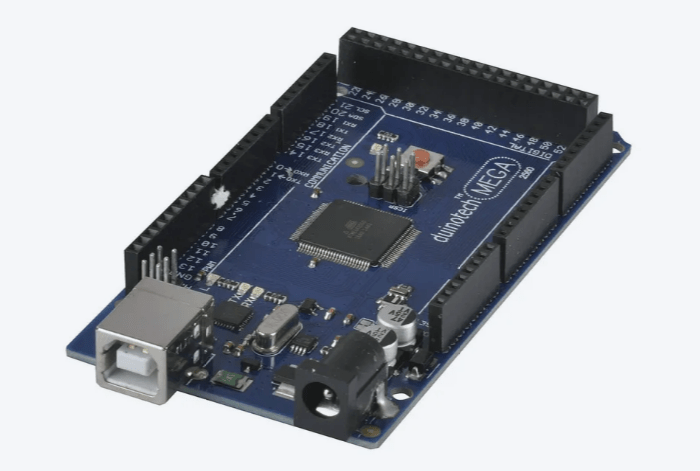
- Arduino Mega 2560 (4× HW UARTs; easy wiring)
https://store.arduino.cc/products/arduino-mega-2560-rev3
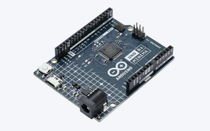
- Arduino Uno (acts as display node)
https://www.jaycar.com.au/duinotech-arduino-compatible-mega-2560-r3-prototype-shield-with-breadboard
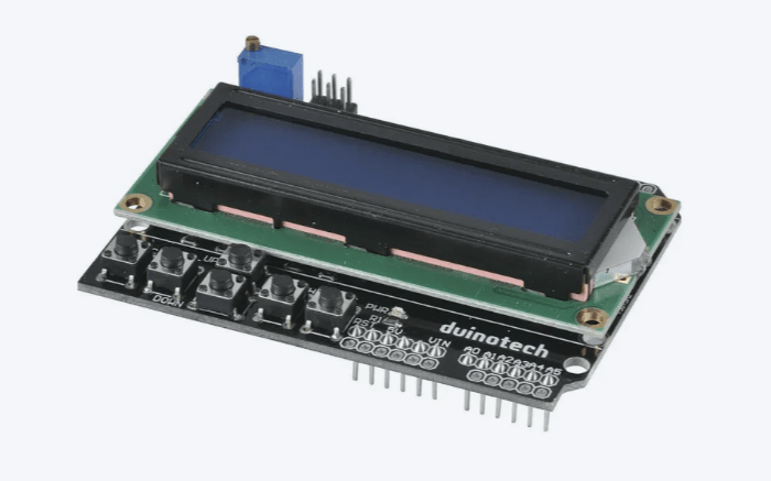
- 16×2 LCD with controller
https://www.jaycar.com.au/duinotech-arduino-compatible-2-x-16-lcd-screen-display-with-controller/p/XC4454
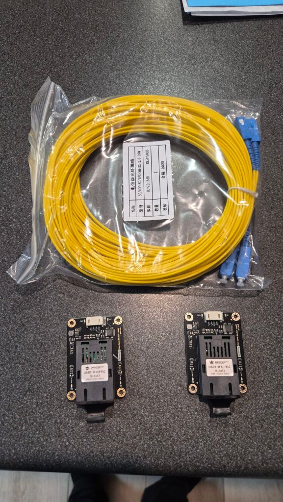
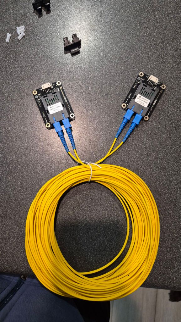
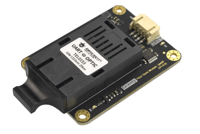
- 2× DFRobot Gravity UART↔Fiber transceivers (TTL UART to optical)
https://www.dfrobot.com/product-2588.html
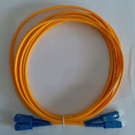
- SC-SC duplex single-mode 20 m patch lead (3 mm jacket)
https://www.aliexpress.com/item/1005008504600535.html
We also had a Mega proto shield in the stack purely because it was already mounted.
Topology & wiring at a glance
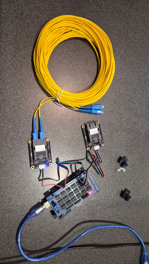
We used a simple point-to-point duplex: Mega UART2 <-> (fiber modules) <-> Uno UART0.
- Cross TX/RX at the UART boundary: Mega TX2 (pin 16) → transceiver RXD; transceiver TXD → Mega RX2 (pin 17). Same on the Uno side.
- Power & logic: modules powered from the host MCU side (common GND per side; fiber isolates between sides).
- LCD on the Uno:
LiquidCrystal lcd(8,9,4,5,6,7) with backlight on D10.
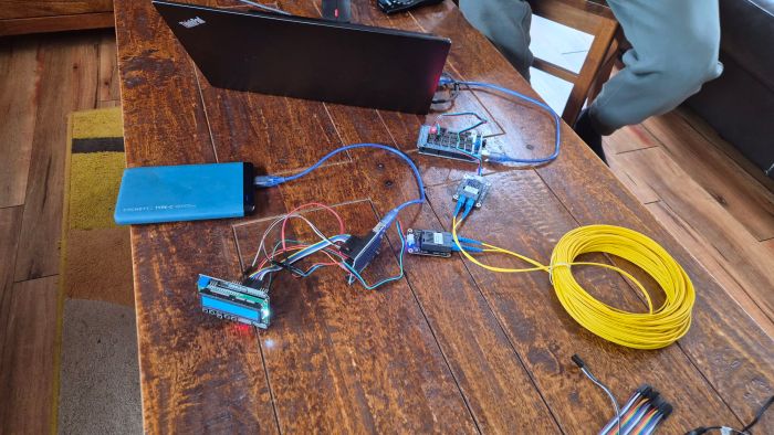
We drew the quick diagram in Fritzing (yeah DFRobot Gravity UART is not part of the standard set so there are UART Wifi modules instead, but you get the point, right?) …
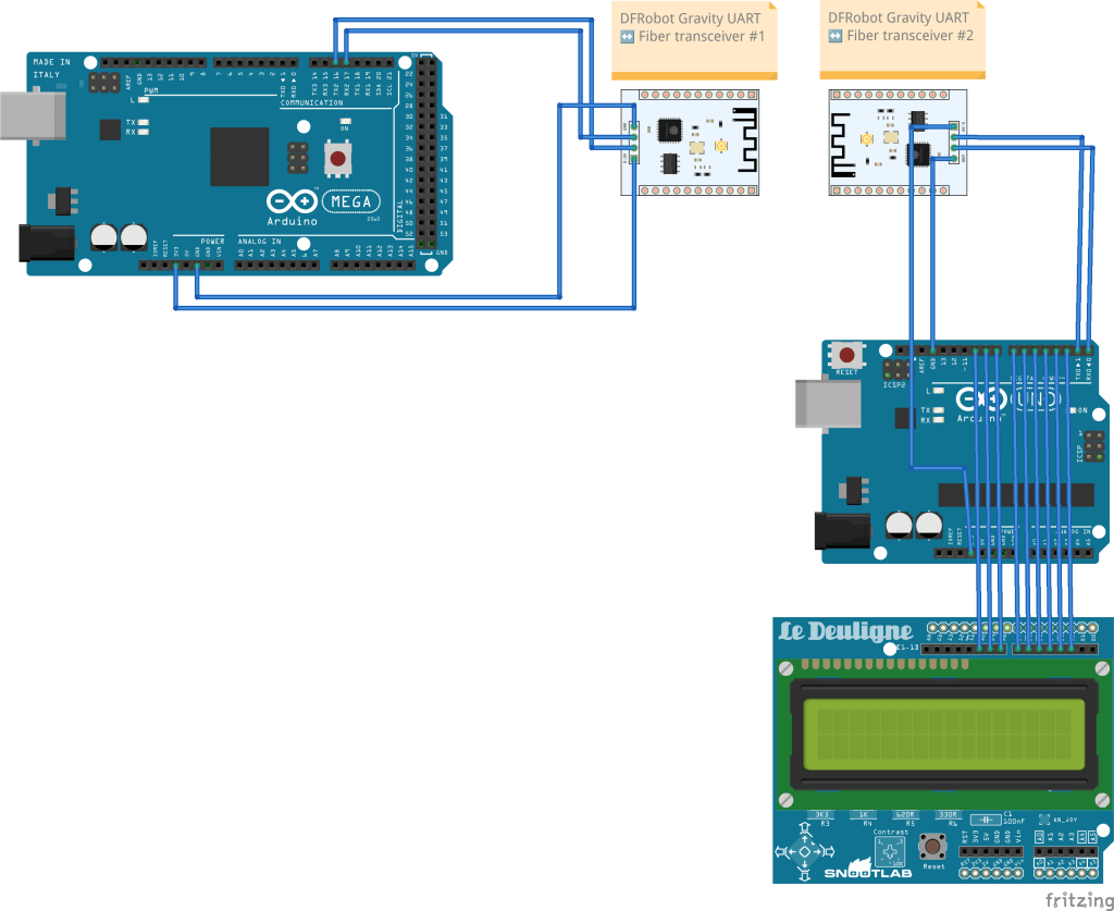
… and then embraced the spaghetti. It’s a demo; it works. 🙂
Firmware roles
Mega 2560 — the “console tee”
- Bridges USB <-> Serial2 (57600 bps).
- Anything you type in the USB serial monitor goes out over fiber; anything coming back is echoed to USB with byte-level logging.
- Optional heartbeat blinks the LED.
// Mega 2560: USB <-> Serial2 (pins 16/17) debug tee
#include <Arduino.h>

static const unsigned long USB_BAUD  = 115200;
static const unsigned long LINK_BAUD = 57600;   // match UNO
static const bool HEARTBEAT = true;

static inline char printable(uint8_t b) {
  return (b >= 32 && b <= 126) ? (char)b : '.';
}

void setup() {
  pinMode(LED_BUILTIN, OUTPUT);
  Serial.begin(USB_BAUD);     // USB console
  Serial2.begin(LINK_BAUD);   // link on TX2=16, RX2=17
  delay(200);
  Serial.println(F("Mega Serial2 tee @57600 (TX2=16 -> UNO D0, RX2=17)"));
  Serial.println(F("Type here; I'll send to Serial2 as [TX2]. Bytes back on RX2 appear as [RX2]."));
}

void loop() {
  while (Serial.available() > 0) {
    uint8_t b = (uint8_t)Serial.read();
    Serial2.write(b);

    Serial.print(F("[TX2] '"));
    if (b == '\r') Serial.print(F("\\r"));
    else if (b == '\n') Serial.print(F("\\n"));
    else Serial.print(printable(b));
    Serial.print(F("' 0x"));
    if (b < 16) Serial.print('0');
    Serial.print(b, HEX);
    Serial.println();

    static bool led = false;
    led = !led; digitalWrite(LED_BUILTIN, led);
  }

  while (Serial2.available() > 0) {
    uint8_t b = (uint8_t)Serial2.read();
    Serial.print(F("[RX2] '"));
    if (b == '\r') Serial.print(F("\\r"));
    else if (b == '\n') Serial.print(F("\\n"));
    else Serial.print(printable(b));
    Serial.print(F("' 0x"));
    if (b < 16) Serial.print('0');
    Serial.print(b, HEX);
    Serial.println();
  }
}
Uno – the “LCD echo node”
- Receives characters on UART0 @ 57600, echoes them back (so Mega can log the return path), and prints them on the LCD second line.
- Backlight is enabled on pin 10.
#include <Arduino.h>
#include <LiquidCrystal.h>
LiquidCrystal lcd(8,9,4,5,6,7);
const int LCD_BL=10;

void setup() {
  pinMode(LCD_BL, OUTPUT); digitalWrite(LCD_BL, HIGH);
  lcd.begin(16,2); lcd.clear(); lcd.print("ECHO @57600");
  Serial.begin(57600);  // D0/D1
  lcd.clear();
}

void loop() {
  while (Serial.available()) {
    char c = (char)Serial.read();
    Serial.write(c);                  // echo back to Mega
    if (c == '\r') continue;
    if (c == '\n') {
      lcd.setCursor(0,1);
    } else {
      lcd.print(c);
    }
  }
}
Gotcha: because the Uno uses D0/D1 for USB and UART, upload the sketch first, then connect the fiber transceiver to D0/D1.
Bring-up checklist
- ✅ TX↔RX crossed (module TXD is MCU input).
- ✅ Non-inverting TTL modules (a test pattern
0x55looked like0x55, not0xAA). - ✅ Both transceivers powered and EN/SD pins strapped as required.
- ✅ Duplex SC-SC fiber seated; if you swap the two fibers, TX/RX flips.
First step: make it talk, then speed-test it
With the echo path working, we ran a quick one-way throughput check by blasting fixed-size chunks and counting bytes at the far end (8-N-1 framing; bps ≈ B/s × 10).
Baseline (bursty sender, 256-byte chunks, 5 s run):
| Baud | Measured B/s | ≈ Line bps |
|---|---|---|
| 115200 | 11 754 B/s | 117.5 kbps |
| 230400 | 22 216 B/s | 222.2 kbps |
| 500000 | 34 730 B/s | 347.3 kbps |
At 115.2 and 230.4 kbps we’re essentially at line-rate. At 500 kbps we plateaued around ~70%—the AVR RX ISR can still momentarily overrun when the sender fires big bursts.
Two quick tweaks push 500 k to ~100%:
- Interleave small TX slices and aggressively drain RX between slices (e.g., write 16 bytes, drain, repeat).
- Bump UART buffers on AVR to give the ISR more headroom:
# platformio.ini
build_flags =
  -DSERIAL_RX_BUFFER_SIZE=512
  -DSERIAL_TX_BUFFER_SIZE=256
With that interleaving change in the loop, 500 k typically lands around 49–50 kB/s (≈ 500 kbps). If a front-end still gets grumpy at 500 k, try 460800 or 250000.
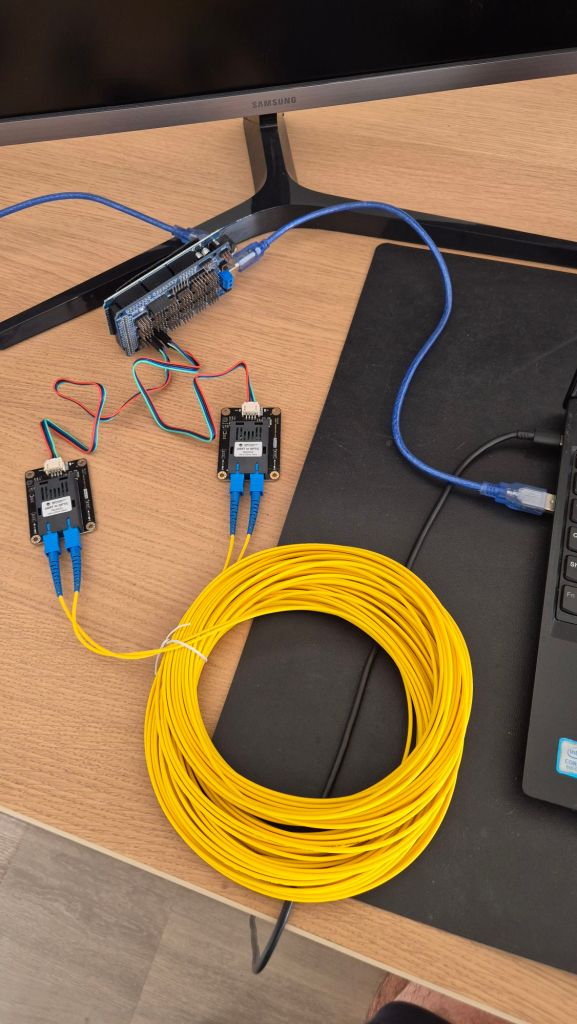
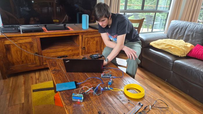
Second step: Demo it so it is clear
With the code & HW above working (thanks Sebi!), it was then easy to show how it really works:
Where this is heading (Phase II comms)
Topology: a star (or sparse mesh) of local edge hubs near actuators/sensors (future Teensy modules) linking back to a central compute. Fiber for the noisy/high-current spans; short local TTL pigtails only.
Protocol plan:
- Keep the fiber hop simple and deterministic: a tiny framed UART protocol (SYNC + LEN + SEQ + CRC16).
- Run MQTT centrally, with hubs speaking MQTT-SN over the UART link (or SLIP-encapsulated packets) and a gateway that bridges into the broker.
- QoS / topics:
- Control: bounded payloads, prioritised.
- Telemetry: ESC rpm/temp at low duty; alarms as retained messages.
- High-rate sensors (LiDAR/video): use a higher-bandwidth branch (see below).
High-bandwidth branch: for LiDAR/camera, plan Ethernet-over-fiber (100BASE-FX/1G SFPs) to the hub, then MQTT/TCP or a custom stream. This keeps the UART path for control/telemetry while heavy data rides a separate lane.
Serviceability:
- OTA updates: publish signed firmware blobs; hubs reboot into a bootloader that streams the image over the same link (CRC32 + version + A/B rollback).
- Diagnostics: per-link BER counters, link up/down, temperatures/voltages, soft resets—exposed as retained MQTT stats.
- Time sync: a tiny time-sync message or PPS-over-GPIO for aligned logs.
What’s next
- Wrap the raw link in the framed protocol and soak-test with motors/ESCs actually running to validate the EMI story under worst-case noise.
- Stand up the MQTT-SN <-> MQTT gateway and a topic map per hub/device.
- Prototype the Ethernet-over-fiber branch for the high-rate sensors.
- Add a simple auto-discovery (hubs publish a retained “hello” with capabilities) and remote diagnostics dashboard.
Project gallery