In continuation on the material preparation and its assessment we prepared the first workshop test matrix for the Phase II TPU envelope material.
This update focuses on the next step: what we are testing, why the current targets changed, what the active plan is, and the first recorded outputs from the strip-loop tests.
What we are testing
The current tests are focused on the delivered `0.13 mm` aliphatic polyether TPU film and the heat-welded lap seam. The immediate questions are:
- how much the material stretches under load
- whether the weld holds under the intended proof-of-concept loads
- whether the strip keeps creeping during the hold
- how much length recovers after unloading
- whether longitudinal and transverse roll directions behave differently
- whether the results are good enough to move toward a closed pressure article
The directionality question matters. The supplier reference sheet lists different tensile strengths:
| Direction | Tensile strength |
| Longitudinal | 576 N / 5 cm |
| Transverse | 459 N / 5 cm |
That may affect the eventual cutting plan, because the weaker direction could become the governing case if it carries the main hoop load.
Revised proof-of-concept pressure basis
Earlier design work used a conservative `300-500 Pa` operating frame, with higher pressures kept as proof or transient references.
For the current Phase II-A proof-of-concept, the target is softer:
- expected maximum speed: about `37 km/h`
- intended demo/operation duration: about `2 h`
- possible inflated duration: up to about `12 h`
Current working interpretation:
| Full-envelope pressure | Interpretation |
| 250 Pa | nominal PoC pressure |
| 300 Pa | strong PoC operating pressure |
| 350 Pa | upper operating / gust margin |
| 500 Pa | proof test, not normal operation |
The purpose of the strip tests is not to force the material to meet the old continuous `500 Pa` assumption. It is to find the practical creep, recovery, and weld-performance limits, then use those results to decide the next pressure article.
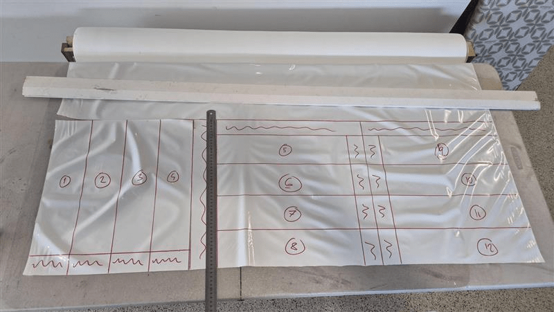
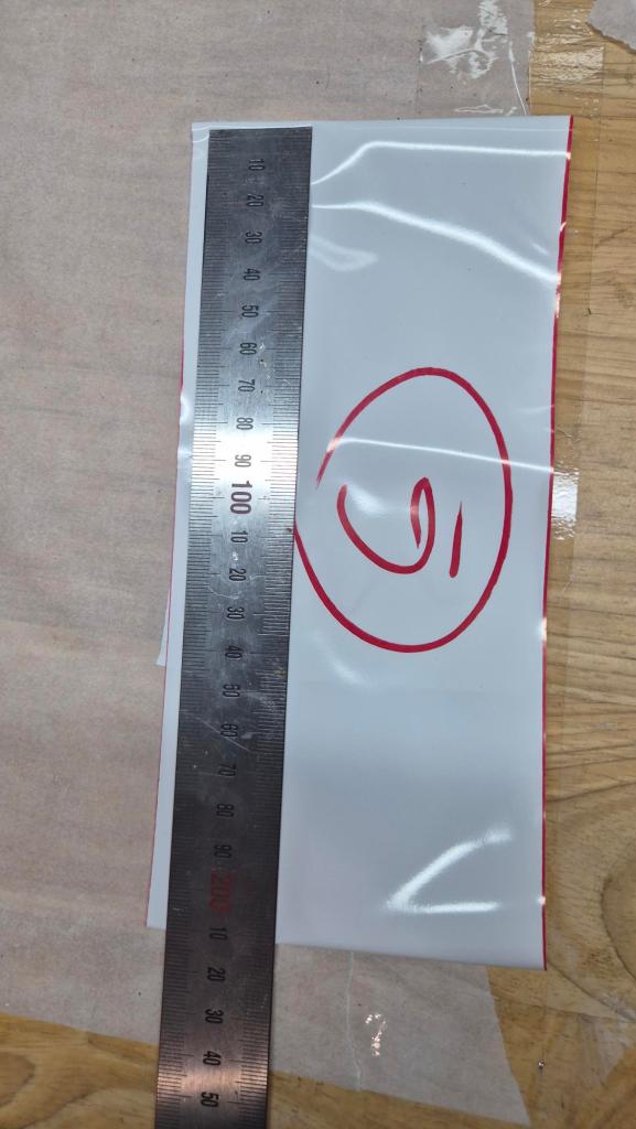
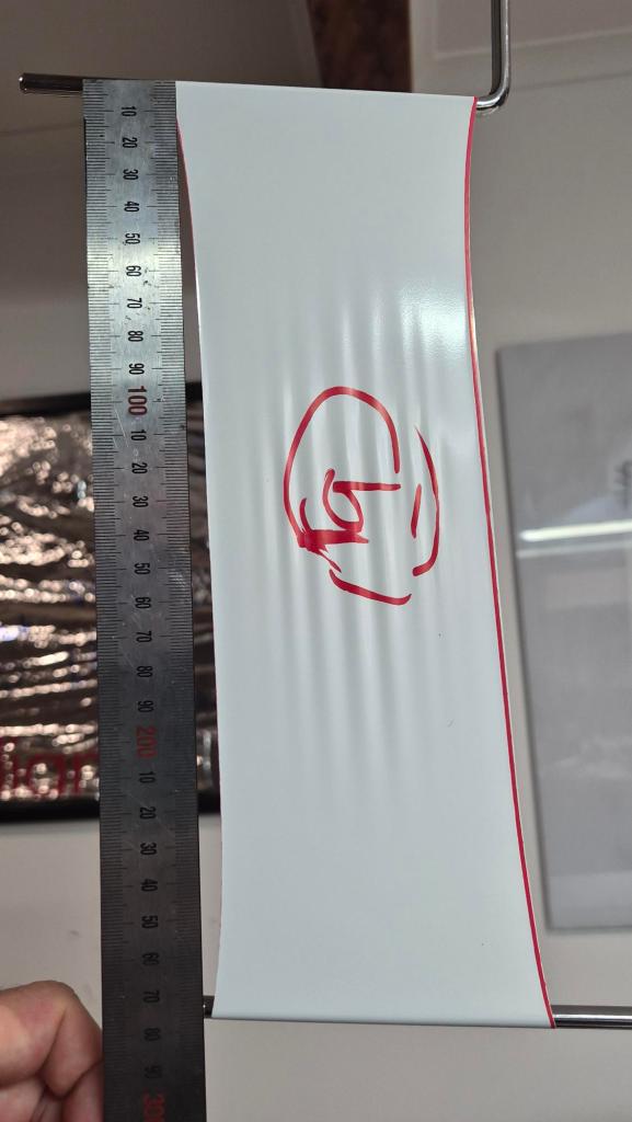
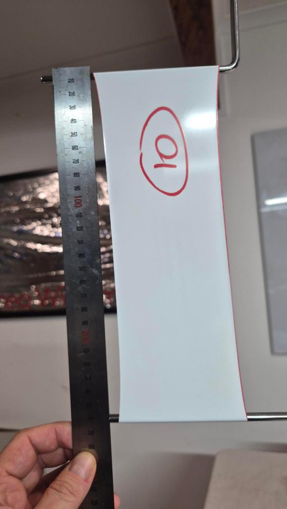
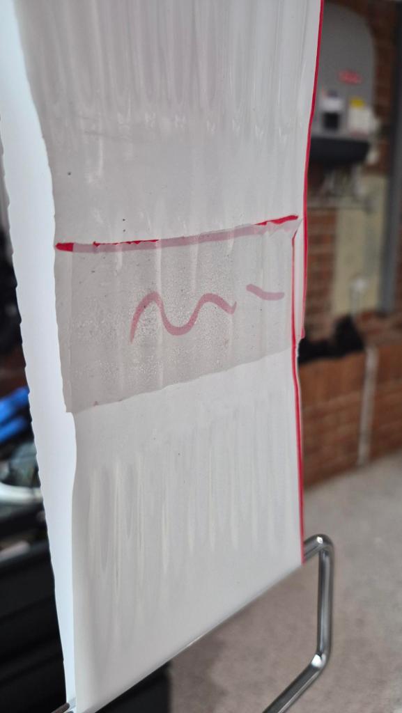
Strip-loop setup
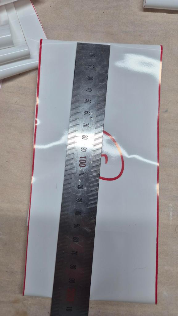
The restarted test set uses 12 welded loops:
- strip width: `100 mm`
- strip length: `400 mm`
- lap seam: `50 mm`
- weld temperature: about `220 C`
- loops `1-4`: longitudinal / roll direction
- loops `5-12`: transverse / cross-roll direction
- average ambient temperature 20C
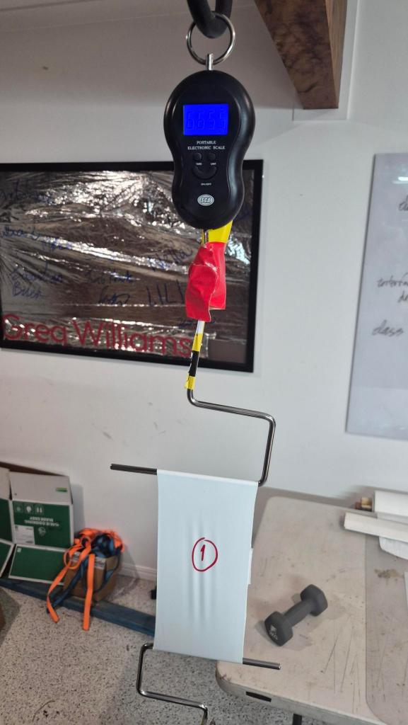
The current test mass is `6.655 kg`, equivalent to about `261 Pa` full-envelope pressure in this strip-loop setup.
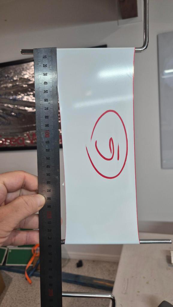
Test log
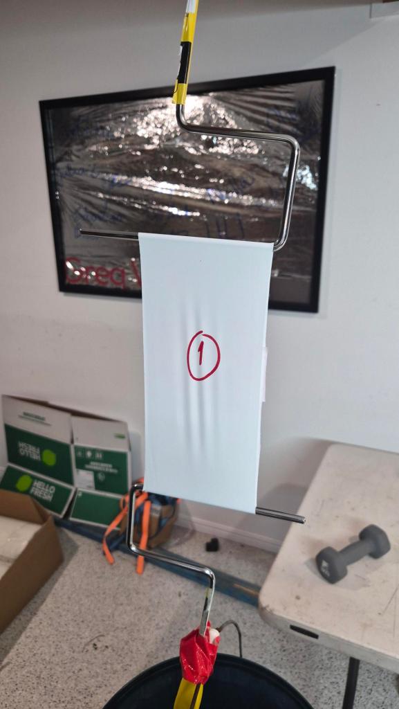
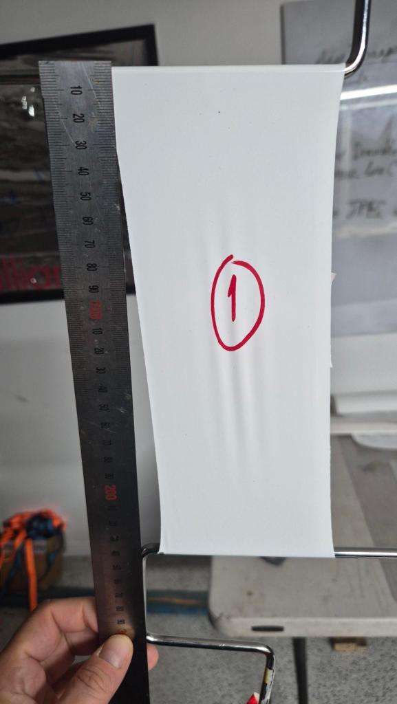
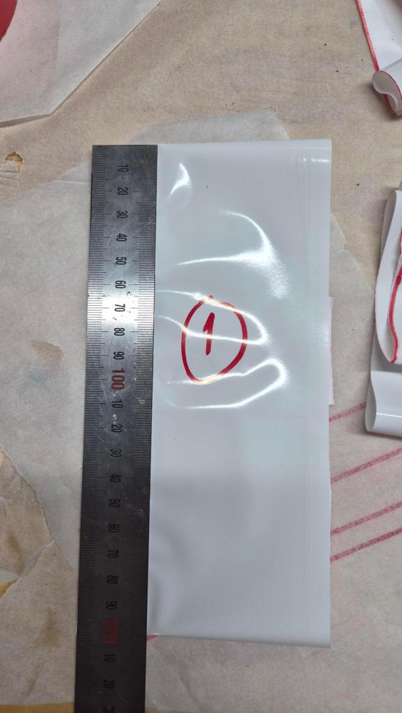
Loop #1: Longitudinal / roll direction
| Time | Elapsed | Load | Equivalent | Length | Observation |
| 2026-06-07 16:10 | 0h | 6.655 kg | ~261 Pa | 420 mm | immediate stretch from `400 mm`; sample holding |
| 2026-06-07 19:10 | 3h | 6.655 kg | ~261 Pa | 440 mm | holding; seam/sample visually happy |
| 2026-06-08 06:30 | 14 h 20 min | 6.655 kg | ~261 Pa | 460 mm | survived overnight; no visible seam |
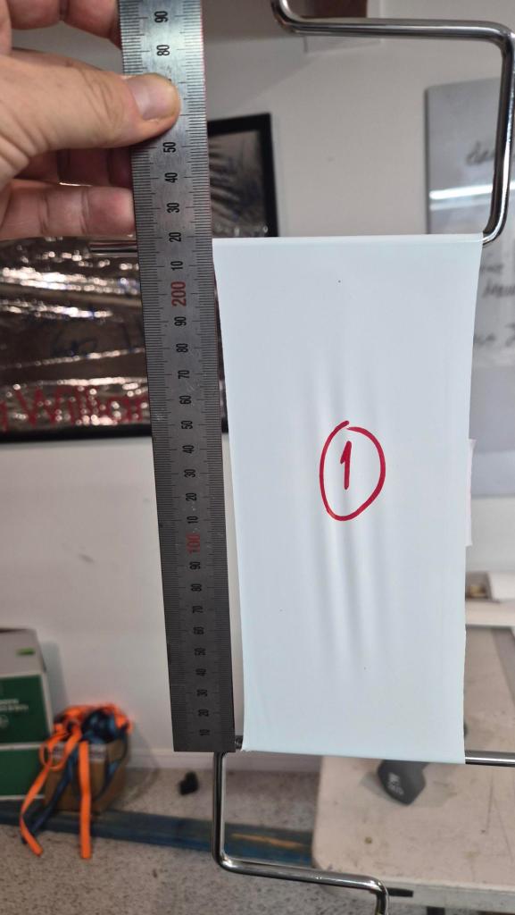
| after unload | instant | none | n/a | 420 mm | immediate recovery after removal from jig |
| 2026-06-08 18:10 | 11 h 40 min | none | n/a | 400 mm | recovered to original length |
Notes:
- original unloaded length before loading: `400 mm`
- the exact `12 h` mark was `2026-06-08 04:10`
- the practical morning check was taken at `14 h 20 min`
- after nearly
12 hoff-load, the sample had recovered back to the original400 mm
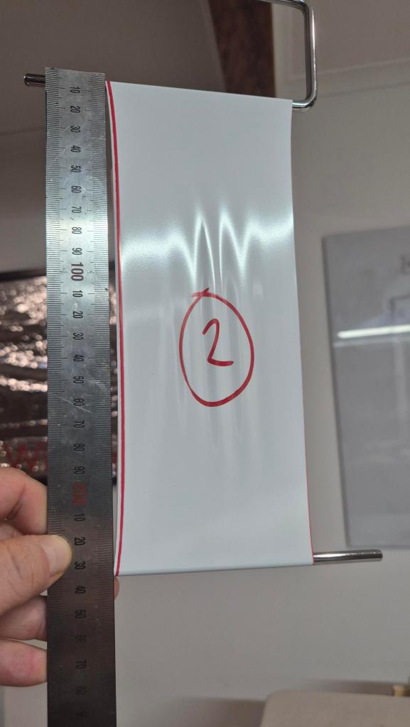
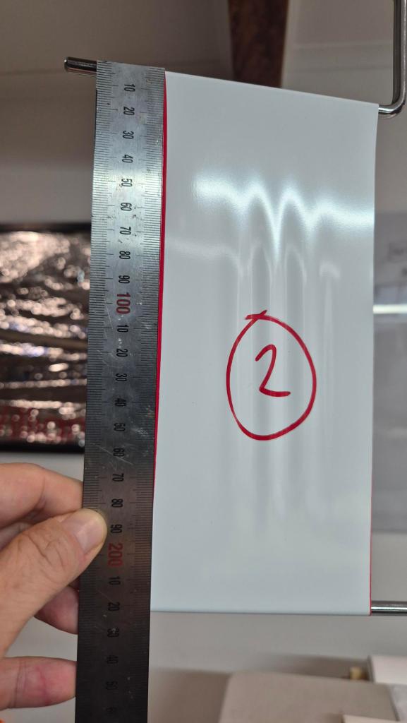
Loop #2: Longitudinal Middle-Margin Hold
| Time | Elapsed | Load | Equivalent | Length | Observation |
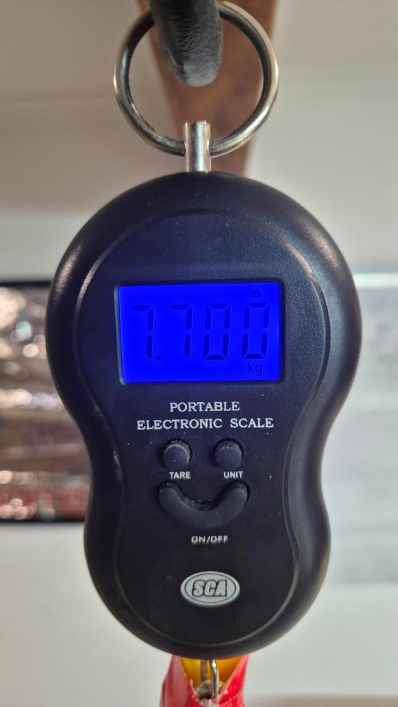
| 2026-06-09 20:15 | 0 h | 7.700 kg | ~302 Pa | 440 mm | |
| 2026-06-09 22:15 | 2 h | 7.700 kg | ~302 Pa | 470 mm | |
| 2026-06-09 22:15 | instant | none | n/a | 420 mm | Instantly recovered after removal from jig |
| 2026-06-10 8:15 | 12h | none | n/a | 400mm | Completely recovered |
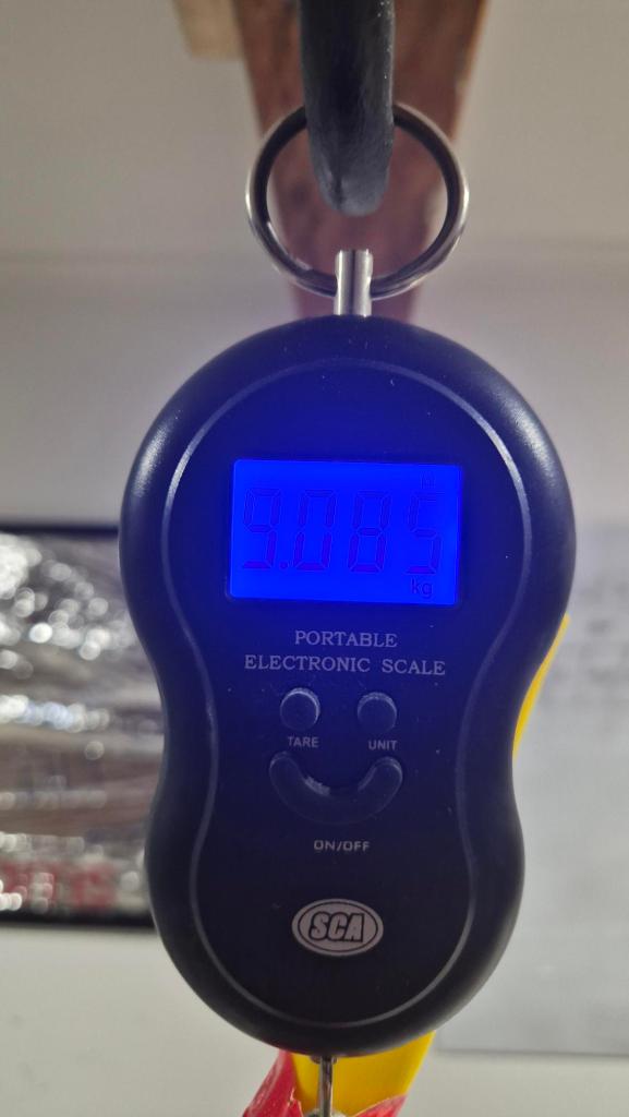
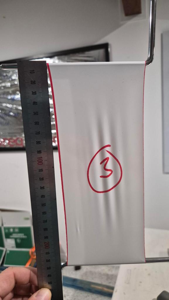
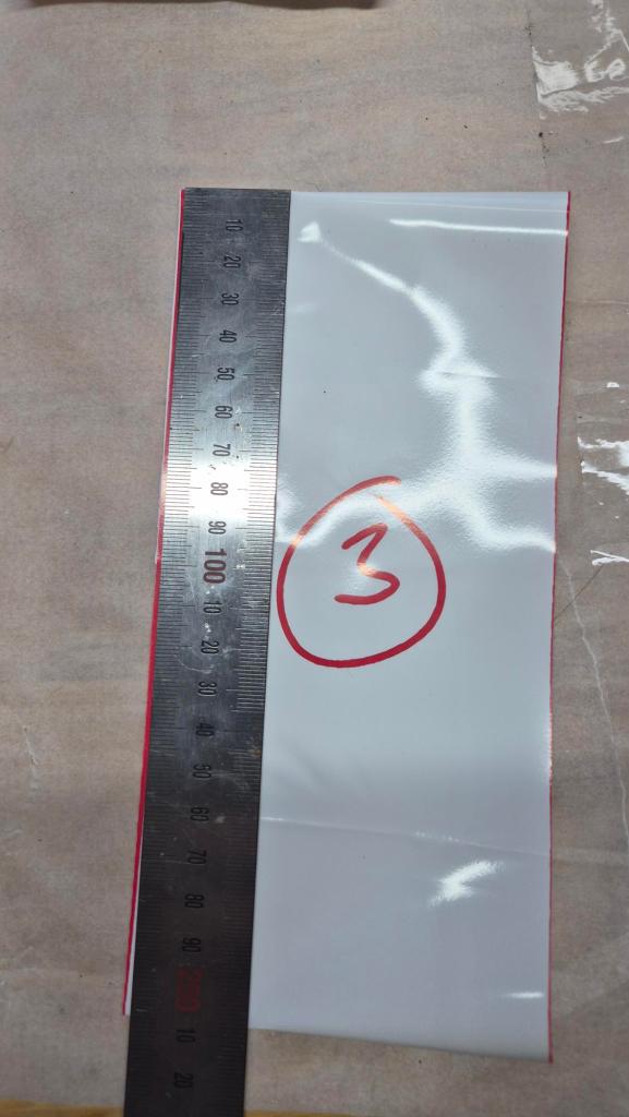
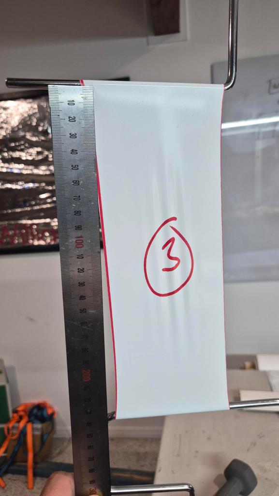
Loop #3: Longitudinal Upper-Margin Hold
| Time | Elapsed | Load | Equivalent | Length | Observation |
| 2026-06-09 06:30 | 0h | 9.085 kg | ~356 Pa | 460 mm | Immediate elongation from 400 mm; 30-60 min upper-margin test started |
| 2026-06-09 07:10 | 40 min | 9.085 kg | ~356 Pa | 480 mm | Removed from jig; seams ok-ish, with minor edge peel-away observed |
| 2026-06-09 07:10 | instant | none | n/a | 415 mm | Instantly recovered after removal from jig |
| 2026-06-09 18:30 | 11 h 20 m | none | n/a | 400 | Recovered completely |
Notes:
- original unloaded length before loading: `400 mm`
- loop
3is longitudinal / roll direction - this load is slightly above the nominal
350 Paupper operating / gust-margin target - minor seam-edge peel on loop
3, after similar observations on loops5and6, supports adding a general seam inspection and repeat-load/cycling check after the current set
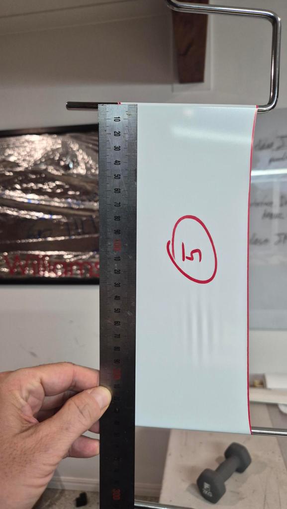
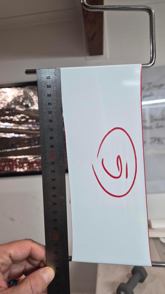
Loop #5: Transverse / cross-roll direction
Loop `5` is important because transverse behaviour may be the governing design case.
| Time | Elapsed | Load | Equivalent | Length | Observation |
| 2026-06-08 06:30 | 0h | 6.655 kg | ~261 Pa | 420 mm | immediate stretch from `400 mm`; second transverse sample started |
| 2026-06-08 18:10 | 11 h 40 min | 6.655 kg | ~261 Pa | ~460-470 | weld had no apparent damage |
| 2026-06-08 18:10 | instant | none | n/a | 430 mm | immediate recovery after removal from jig |
| 2026-06-09 06:20 | 12 h 10 min | none | n/a | ~410 mm | recovered further; similar seam-edge peel defect observed as loop 6 |
Notes:
- original unloaded length before loading:
400 mm - loop #5 is the first governing-direction transverse check at the nominal PoC load.
- loaded length before removal was estimated by feel/handling rather than recorded as a precise ruler measurement.
- the observed seam-edge peel on loops
5and6suggests the weld process needs inspection before treating transverse nominal-load survival as a clean pass.
Loop #6: Transverse / cross-roll direction
Loop `6` is to confirm observations through the loop #5.
| Time | Elapsed | Load | Equivalent | Length | Observation |
| 2026-06-08 18:10 | 0h | 6.655 kg | ~261 Pa | 430 mm | immediate stretch from `400 mm`; transverse sample started |
| 2026-06-08 18:10 | 11 h 40 min | 6.655 kg | ~261 Pa | ~460-470 | weld had no apparent damage |
| 2026-06-08 18:10 | instant | none | n/a | 430 mm | immediate recovery after removal from jig |
| 2026-06-09 16:25 | 22h | none | n/a | 410 mm | recovery/set checked; this may include cutting, welding, or measurement error |
Loop #9: Transverse / cross-roll direction
Loop `9` is important because it was first short higher-load samples.
| Time | Elapsed | Load | Equivalent | Length | Observation |
| 2026-06-09 15:40 | 0h | 9.095 kg | ~356 Pa | 460 mm | |
| 2026-06-09 16:25 | 45 min | 9.095 kg | ~356 Pa | 540 mm | |
| 2026-06-09 16:25 | instant | none | n/a | 420 mm | immediate recovery after removal from jig |
| 2026-06-10 6:25 | 14 h | none | n/a | 400 mm | Complete recovery |
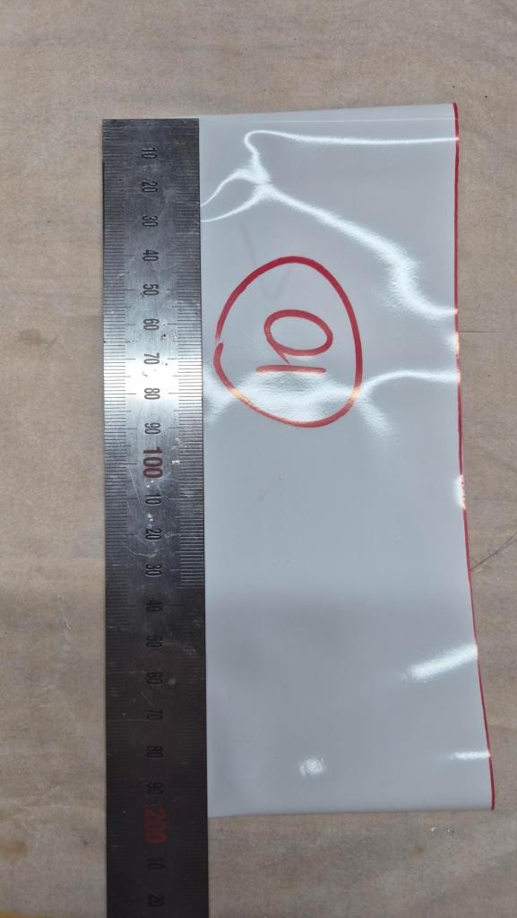
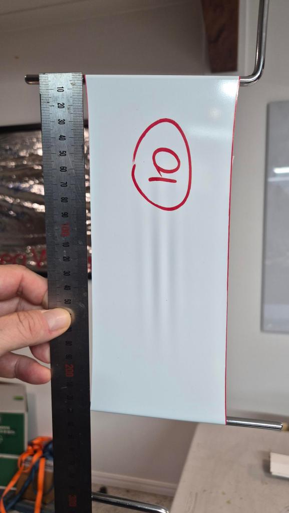
Loop #10: Transverse / cross-roll direction
Loop `10` is loop `9` cross-check
| Time | Elapsed | Load | Equivalent | Length | Observation |
| 2026-06-09 16:25 | 0h | 9.095 kg | ~356 Pa | 460 mm | |
| 2026-06-09 17:05 | 40 min | 9.095 kg | ~356 Pa | 540 mm | |
| 2026-06-09 17:05 | instant | none | n/a | 420 mm | immediate recovery after removal from jig |
| 2026-06-09 22:15 | 5 h 10 min | none | n/a | 400 | complete recovery, weld clean |
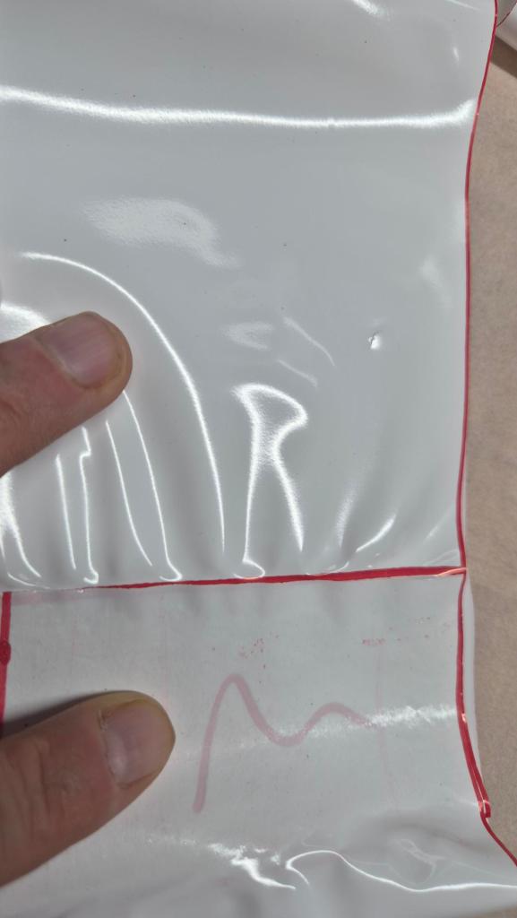
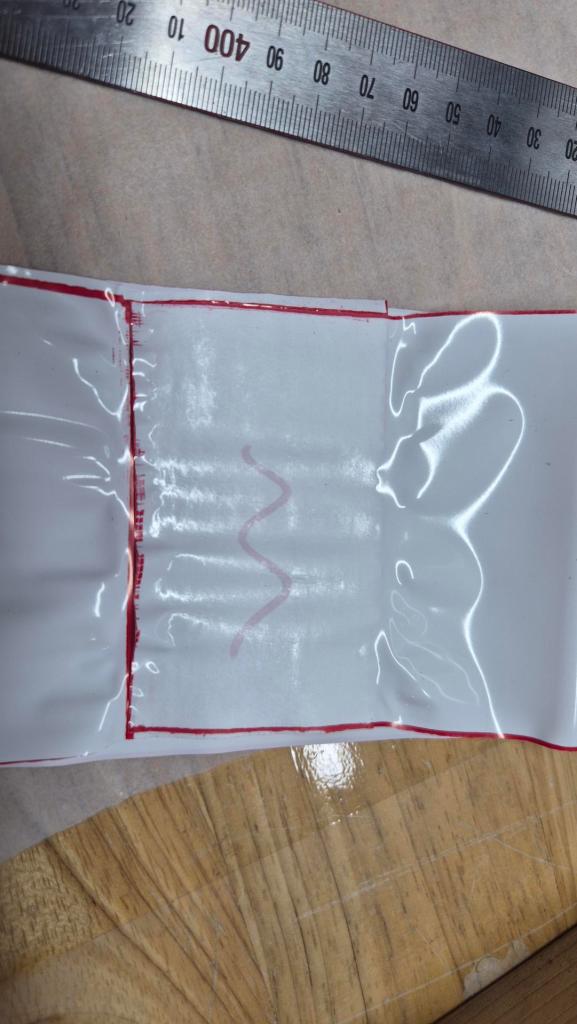
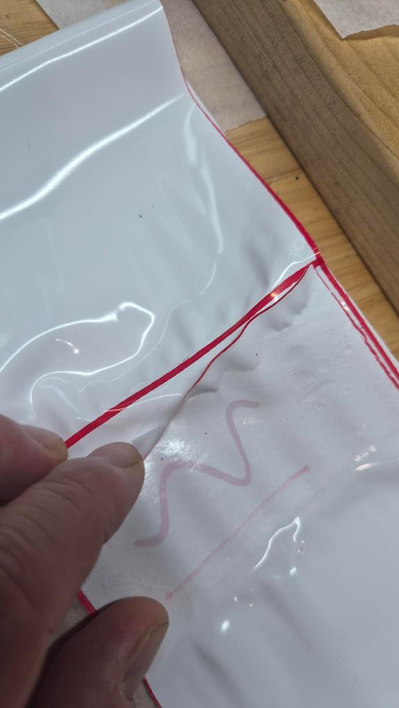
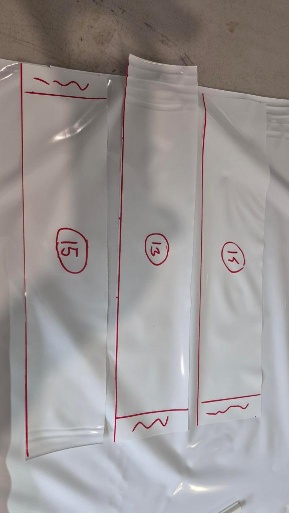
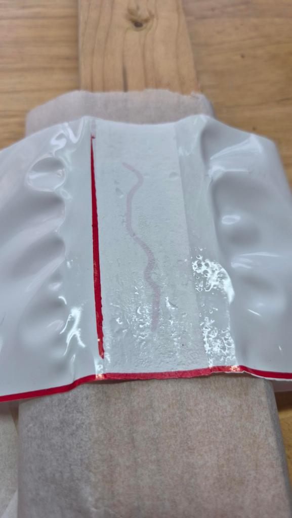
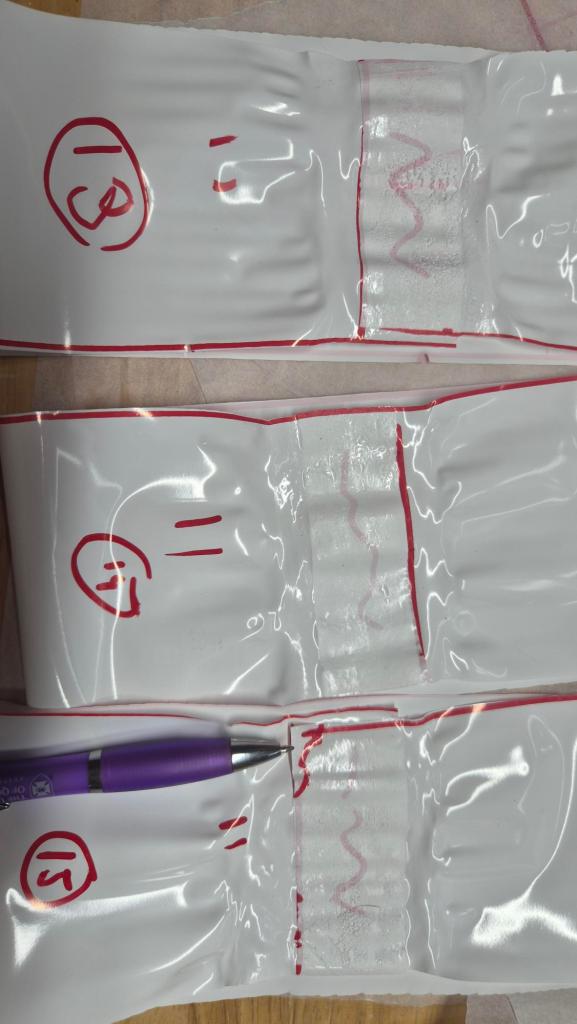
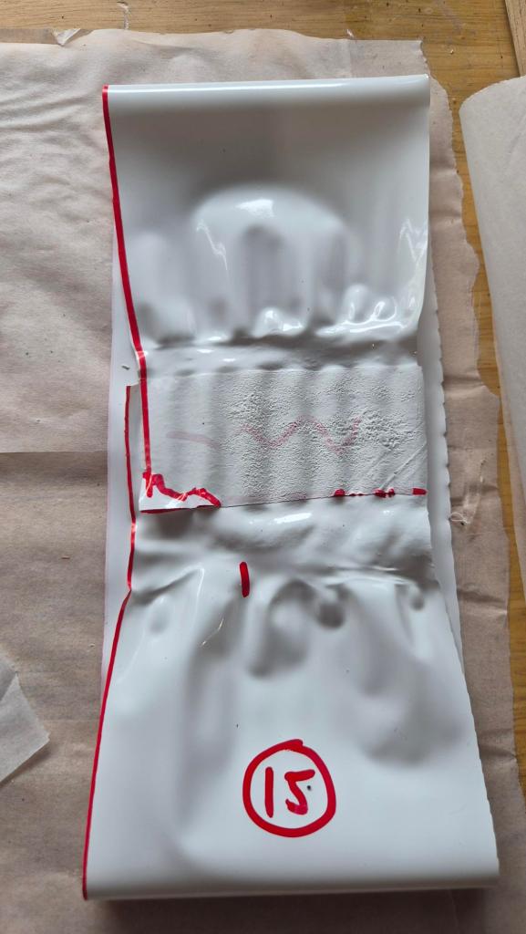
Follow-up `30 mm` seam check
Because the 50 mm overlap samples often appeared to peel at the outer edge while retaining a strong central bond, we made three fresh longitudinal loops with a deliberate 30 mm weld overlap at about 220 C.
All three were tested at 7.7 kg, about 302 Pa equivalent:
| Loop | Test history | Result |
| #13 | 2 h, then another 1 h 50 min repeat cycle | no damage observed |
| #14 | about 4 h 25 min hold repeated cycle | no damage observed |
| #15 | about 1 h 20 min, then another 2 h 10 min repeat cycle | one external-corner defect was marked; later judged likely setup damage, and it did not propagate under the repeat cycle |
This is a useful result because it separates the apparent material/weld-center strength from the edge-peel problem. A deliberate `30 mm` seam, aligned under the effective hot/pressure zone, appears stable at the strong-operating loop load.
Final results
The first controlled longitudinal result is encouraging: the 220 C / 50 mm lap seam survived overnight at about the nominal PoC pressure equivalent without visible seam damage, and recovered to the original 400 mm length after nearly 12 h off-load.
The nominal transverse samples also survived their holds, but loops 5 and 6 both showed seam-edge peel. That changes the interpretation: the material strength is still promising, but the weld process needs closer inspection before we treat the current seam as qualified.
The higher-load samples are useful but mixed. Loops 3, 9, and 10 are encouraging because they recovered to about the original 400 mm length after unloading, even after upper-margin loading. At the same time, the loaded elongation at the upper-margin load is large, and several samples now point back to seam-edge fusion as the issue to control.
The ~300 Pa / 2 h strong-operating checks have now run in both directions. Loop 2 covered the longitudinal case and recovered to about 400-410 mm. Loops 7 and 8 repeated the same load in the transverse direction; both reached about 500 mm while loaded and later recovered to 400 mm. That is encouraging enough to keep the strong-operating case alive, while still watching seam quality closely.
The proof-zone tests near 12.5 kg / ~490 Pa are a different story. Loop 4 in the longitudinal direction reached about 620 mm after 10 min and instantly recovered to 420 mm. Transverse loops 11 and 12 stretched much more, reaching about 920 mm and 1020 mm, with instant recovery only to 460 mm and 520 mm. Unless later recovery is surprisingly complete, this looks like the beginning of a practical no-go zone for the current loop geometry and weld process.
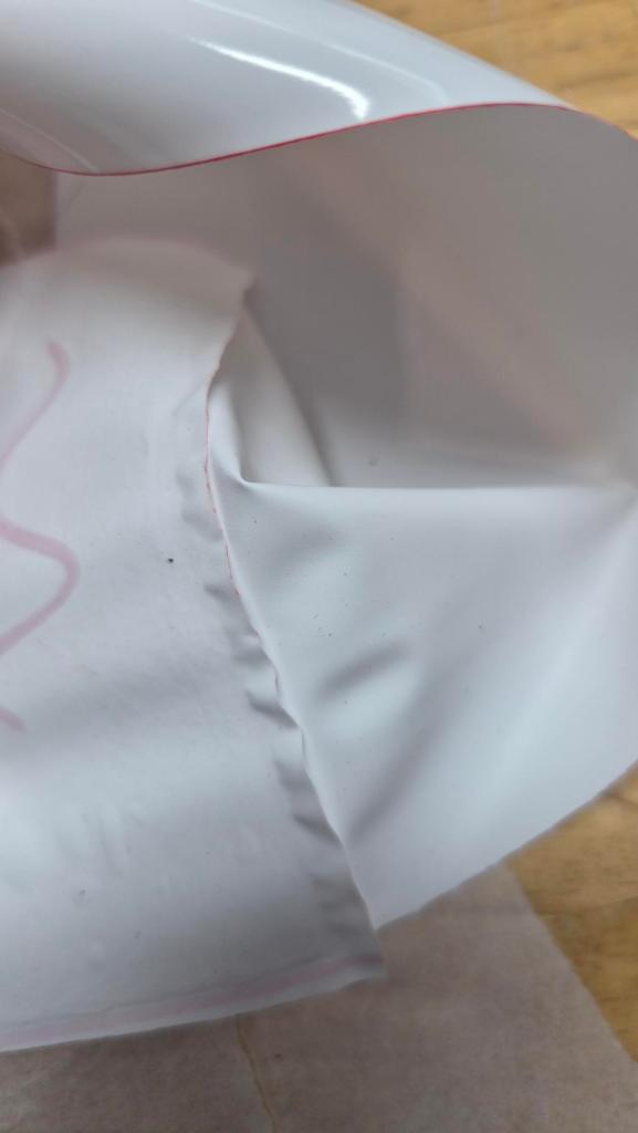
The post-test seam review also shows a pattern. The maximum peel-away depth was usually worse on the outer seam edge than the inner seam edge, while the center of the seam often still appeared strongly bonded. That points toward a weld-process issue more than a simple material-strength issue: alignment, iron heat distribution, pressure distribution, backing compliance, the baking-paper stack, or the thermal sock may be giving a reliable central bond but weaker edges.
The follow-up 30 mm seam loops support that interpretation. When the weld was deliberately centered on the apparent effective bond zone, the loops survived repeated strong-operating load cycles, and the one known damaged corner did not grow.
The main caution is that survival is not the same as qualification. The real decision points are:
- creep rate during the hold
- permanent set after unloading
- seam-edge peel or weld-edge movement
- repeatability across more samples
- comparison between longitudinal and transverse directions
The strip-loop gate is now good enough to move toward an air-only pressure article, with the weld process changed from a nominal 50 mm overlap to a controlled 30 mm effective seam. The next question is no longer whether coupons can survive the strong-operating load; it is whether a closed article can be built leak-tight, hold pressure, and keep its seams stable.
The 400 mm x 1200 mm cylinder is the cleaner next article for validating the real hoop/longitudinal seam geometry, unless a smaller pillow is needed first to rehearse fittings or gauge plumbing.
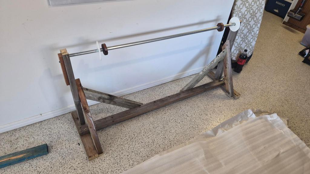
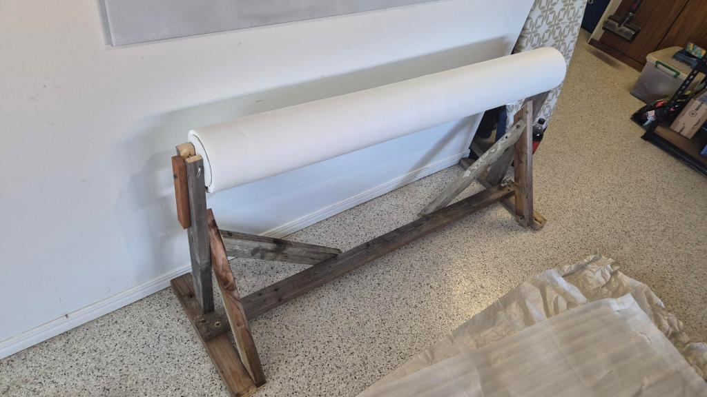
Finally huge thanks to Serge for preparing awesome roll-holder jig, these rolls are seriously heavy! Thank you Serge! 🙂

Tu váhu máš z alíku ?
LikeLike