This was supposed to be a few quick checks of our blimp frame. We are now at V135. So yes, the “quick” part went very well. 🙂
I have been having a lot of fun with SkyCiv. It lets us build a structural model, put loads on it and see how the frame and tethers respond. For a hobby project with a fairly ambitious collection of carbon tubes, batteries and bits of string, that is enormously useful. I would much rather find a bad idea on the screen than after making the parts (One of our Phase I lessons).
SkyCiv did a lot of the heavy lifting in this round of development. We could change one thing, run the calculation, compare it with the previous version and keep the results. Its API also let us automate batches of “what if?” questions and in cooperation with Codex we certainly found plenty of those.
There were other tools alongside it in play: OpenSeesPy for independent comparisons, OpenSCAD for geometry checks, and Autocad Fusion 360 for the actual layout. Here is the slightly condensed story….. very slightly, judging by the version numbers.
It started with a beam
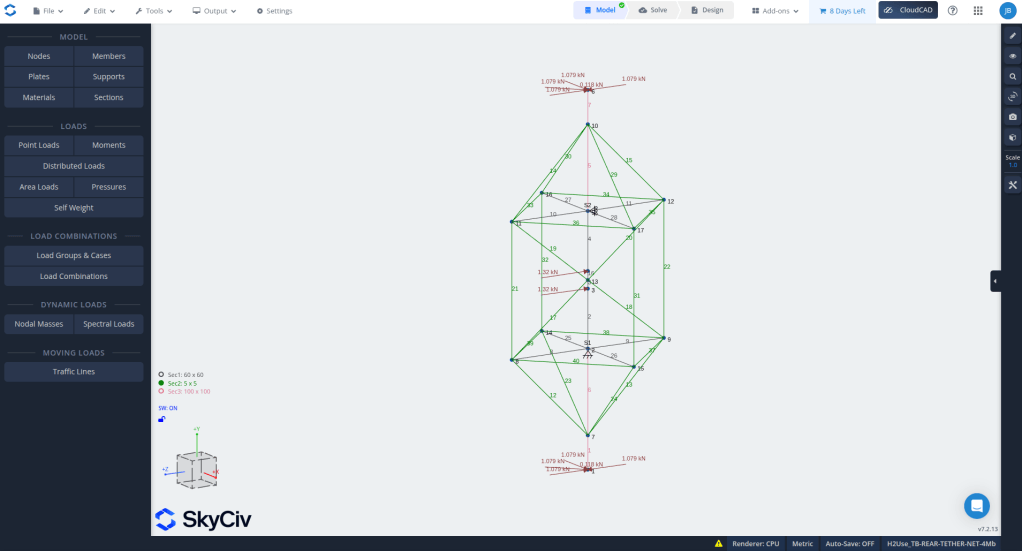
The early model was deliberately simple. V1 added the keels and a basic ground-support arrangement so we could start asking sensible questions. Where does a load enter? What carries it? What stops the whole thing moving? Easy questions to ask, much more difficult to answer, but good to have them!
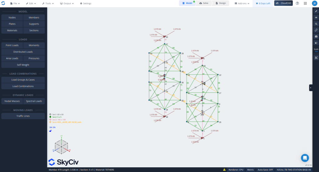
By V19–V27 we were placing the battery, tanks and other weight into more useful places in the model. A single lump of “vehicle weight” is convenient, but a battery hanging from a particular part creates an arm and arm creates a moment and the frame needs to handle it.
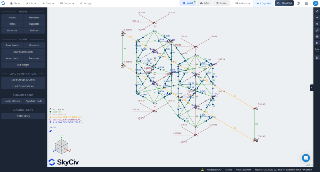
Some nice-looking ideas did not survive the maths
Tried/brainstormed longer members, different bracing and arrangements that looked lighter on screen. Several did not behave nearly as nicely once we included their weight and applied the loads. That is one of the things I really appreciated about SkyCiv: we could explore an idea and find out why it was troublesome before getting too attached to it. Codex helped preparing loading groups so we can quickly iterated of multiple scenarios (30+) on every change.
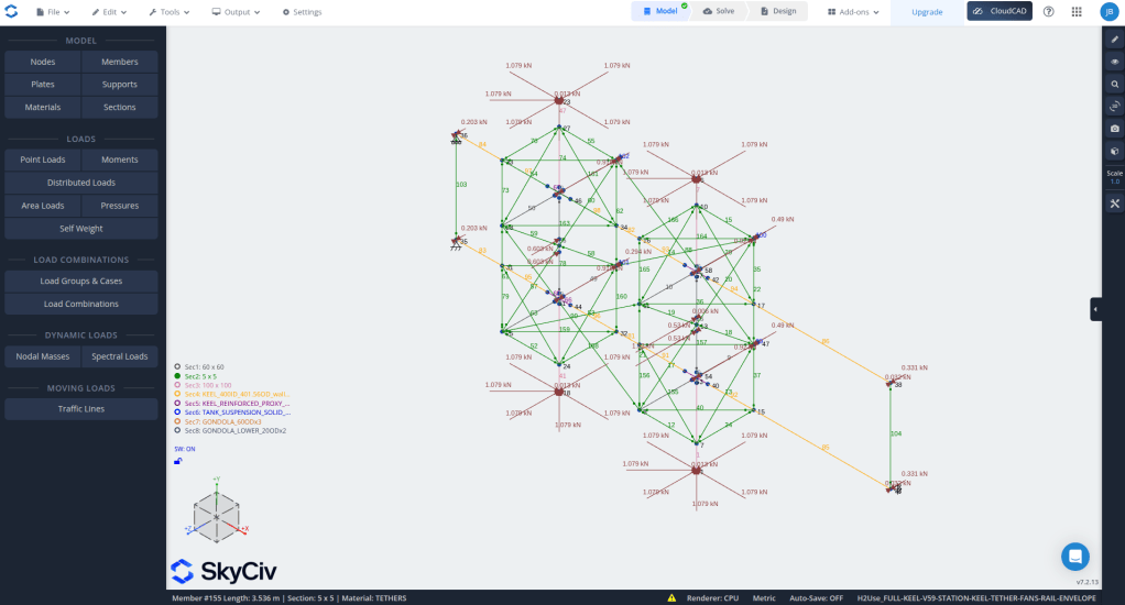
Adding tethers came up with some additional complexity. They pull, but they do not push. A line can be doing very little in one situation and become important when the load changes direction. So removing a slack-looking line from one screenshot is not much of a design method.
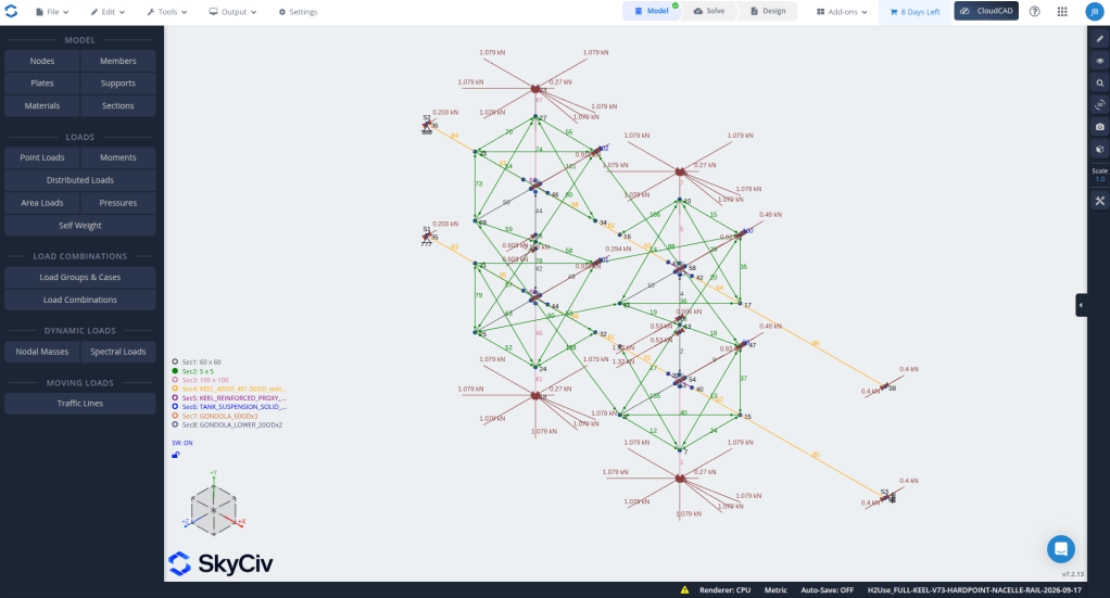
Through these iterations we worked through the network, fixed an accidental loss of symmetry and tested smaller sets of tethers. V72 solved all 33 cases in that particular study. A useful milestone! It still did not cover every gust, handling mishap or real-world connection, but it gave us something much better to work from.
The motors wanted their own bit of attention
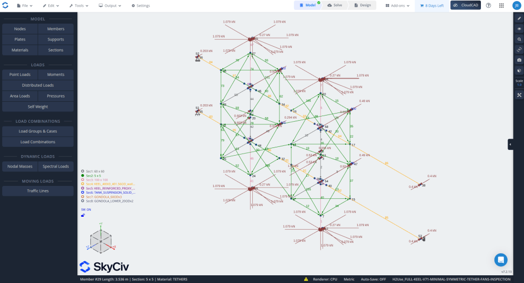
Then we added forces from motors – tilting the thrust downward/upward produced some rather large movements. Tried lowering the main arms by 200 mm and then 400 mm, but that came back with some ugly moment forces. The motor pivot and its offset needed a proper local design; moving a big part of the frame was a poor substitute.
When two calculations disagree, start small
SkyCiv and our local OpenSeesPy model did not always agree about the assembled tether network. Some cases would not converge either. “Converge” is the solver finding a consistent answer – a failure to do so is a reason to investigate, not automatically proof that a real tube has broken.
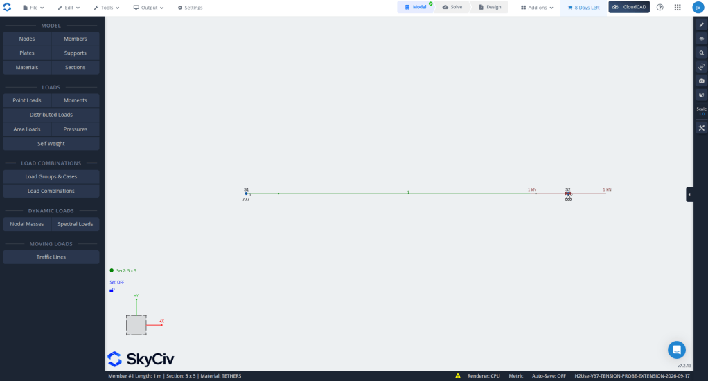
We went right back to a single one-metre tension member. Both programs gave the same extension under a 1 kN pull, and both stopped it carrying compression. Good! That helped rule out some basic mistakes, even though the larger-model disagreement still needed more work.
And sometimes you need to look at the shape again
OpenSCAD was useful for checking the things that are easy to miss in a busy structural picture: empty space, collar positions, propeller clearance and envelope volume. Fusion then helped us see how the proposed hardware might actually fit together. A beautifully coloured result is not much help if two parts want to occupy the same space.
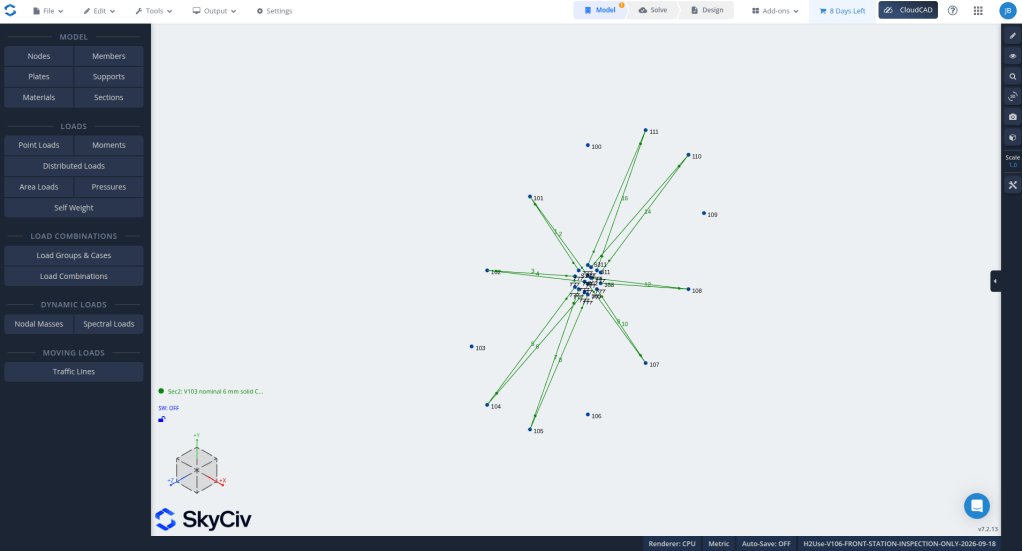
One small SkyCiv fixture was particularly helpful. We tested whether a shallow pair of batons could carry loads along the vehicle. Under that little test load, the predicted movement was about 308 mm. That was enough to send us back to the drawing board. The longitudinal load belongs in the keel – we cannot quietly ask those shallow batons to do the job.
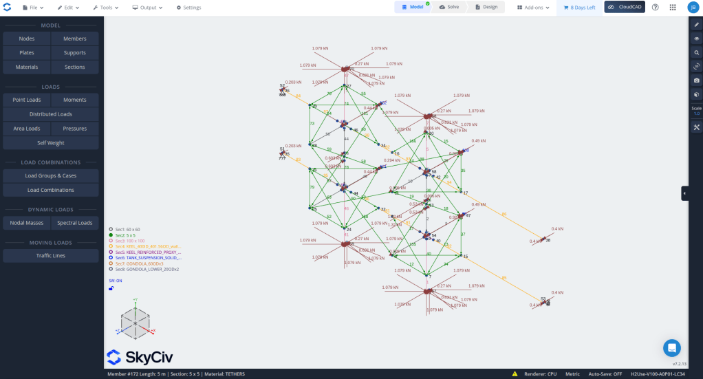
We also moved battery loads around, tried different control directions and made the balancing forces explicit. All rather less glamorous than a new render, but this is where SkyCiv earned its place in the project: we could keep asking questions and see the consequences.
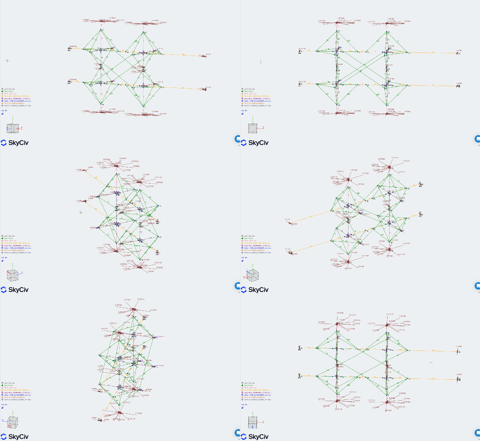
V125: the frame was not the only thing needing a fix
At one point the upward-thrust case stubbornly refused to solve. Even a tiny amount of forward thrust caused trouble. Reducing the thrust looked like a possible answer, until we found two problems in our model setup: a missing balancing longitudinal load and a missing restraint against the whole model rotating in yaw.
V125 corrected those. No bigger tubes, no extra tethers. Both of the retained SkyCiv thrust cases then converged. That was a very useful reminder to check the question we are asking the software before redesigning the aircraft around its answer.
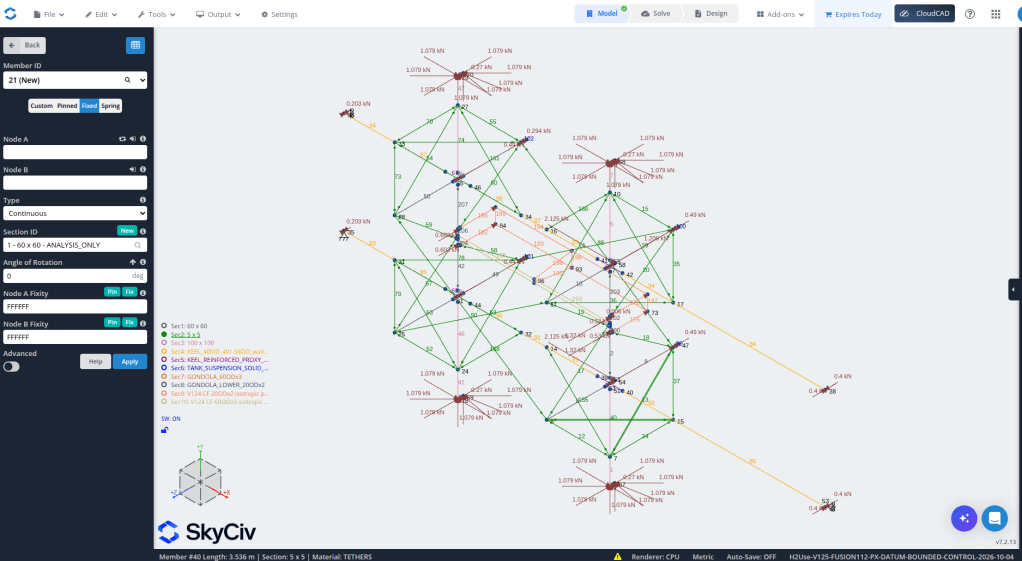
Those two cases gave movements of roughly 135 mm downward-thrust and 114 mm upward-thrust. Useful numbers to investigate, not permission to declare the frame finished. Our matching downward case in OpenSeesPy still did not converge, so that comparison was not closed either.
Serge’s suggestion, and a less awkward gondola
Credit to Serge here: he suggested lowering the gondola and battery. That gave us another layout to explore and helped steer this part of the development. Thanks, Serge!
We worked through the lower arrangement and kept a two-metre gondola. Then there was the fairly practical problem of the lower diamond tethers getting in the way underneath it. Could we bring them to the floor ends instead, and use the existing crossbar between them?
That became V134. SkyCiv let us test the rerouting before committing to the hardware. Both retained cases converged: LC24 means full forward thrust tilted 10 degrees down, and LC25 means 10 degrees up. The obstructing route was gone, but its forces had to go somewhere. The floor and its joints now have a real job to do.
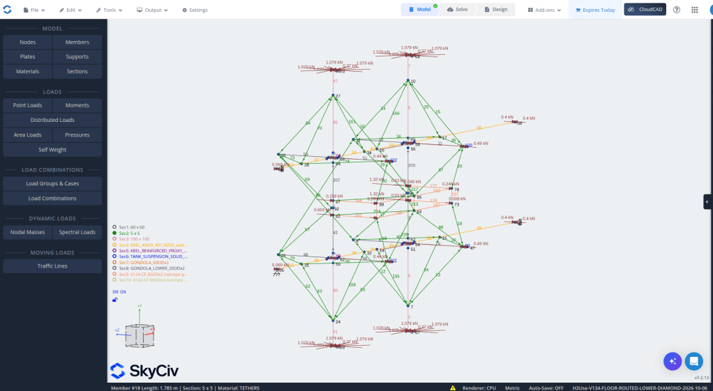
V135: bring the tank anchors into the picture
V135 is our current analysis starting point. Twelve tether ends now attach at the lower tank collars, and four mast extensions reach those connections. The corresponding Fusion layout is saved as v127. We have reached 90 nodes, 137 members and 42 tension-only tethers. Quite a journey from that first beam.
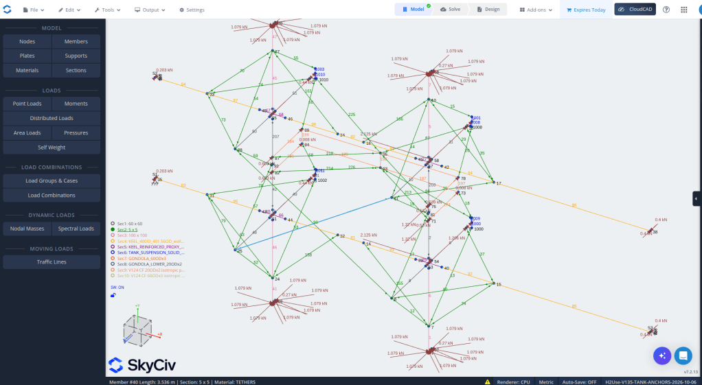
The collars are still represented by simplified connections in the calculation. We have to design and test the real things. Also, four 50-litre tanks give us 200 litres of capacity, but these operating calculations contain only 40 kg of water (each). Full tanks, sloshing water and landing on the tank bottoms remain separate questions.
Yes, we tried putting 120 kg payload in it
Our intended Phase IIa+b payload is still 1 kg (alongside the 100 kg battery). The 120 kg payload was a deliberate stress test. We moved the battery and payload forward and backward to see what became unhappy. It was not a sudden plan to fly another 120 kg!
This is where the SkyCiv API was especially useful. We ran 74 follow-up cases covering placement, tether loss, stiffness, sleeve weight and other variations. All 74 converged. Rear concentration generally made movement worse in these tests, where forward support helped, although that also changes balance and trim. There is no “put everything at the front” shortcut.
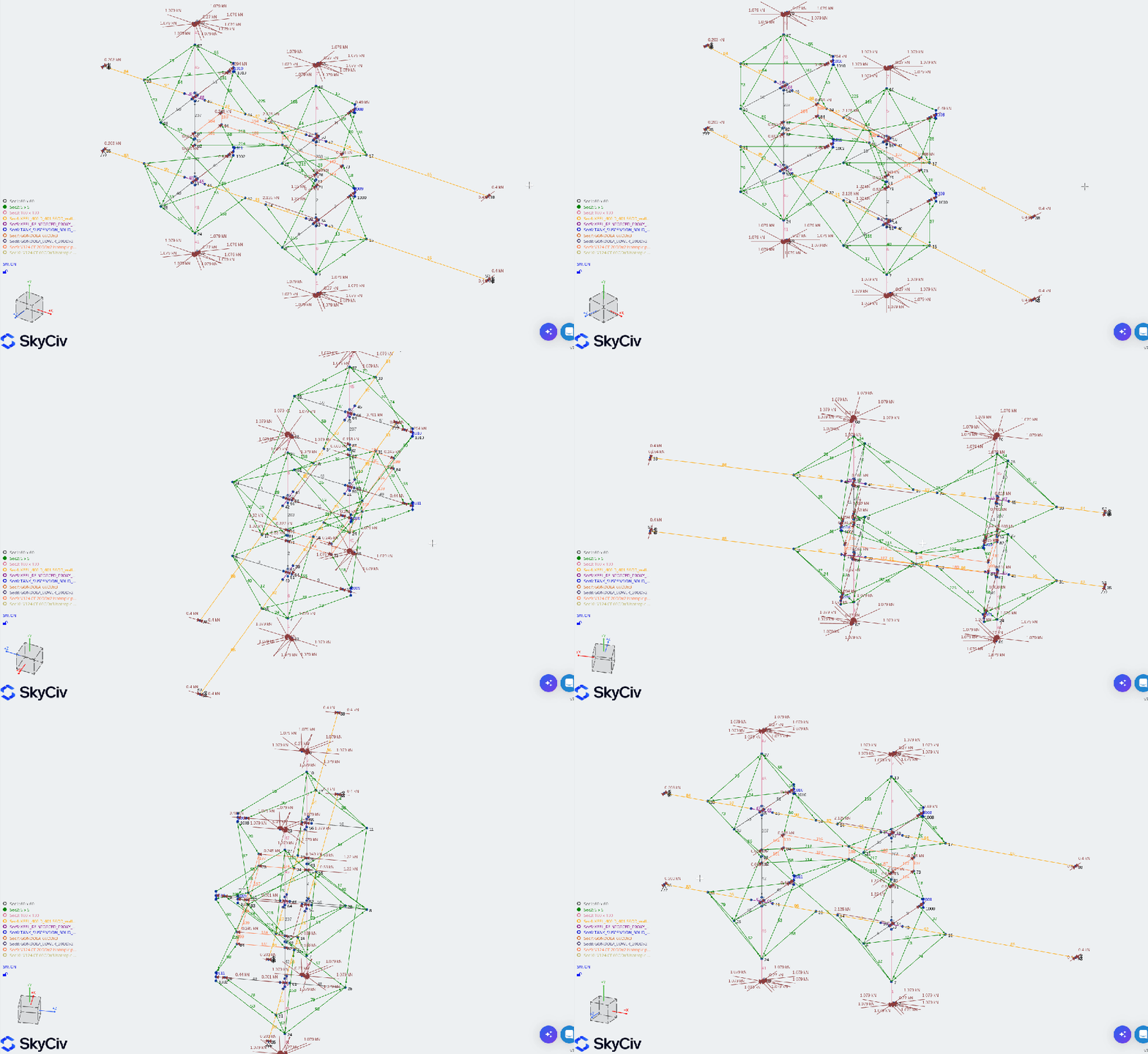
We then ran another 20 cases around the actual one-kilogram mission, and those also converged. At the reference tether stiffness, the ordinary down/up thrust cases gave about 140 mm and 112 mm of frame movement. Softer assumed rope and roll loads produced much more movement, so real rope measurements and clearance checks are still on the list.
The current tether candidate is 1,500 lb Kevlar. Its advertised breaking load is about 6.67 kN, compared with roughly 2.28 kN peak tether demand in those ordinary cases. That looks more encouraging than the earlier 1,000 lb option. A bigger number on the spool does not finish the job for us, those terminations / knots will be still interesting to see developed and tested.
One very large number deserved a second look
One scary result reported an enormous movement inside a tether. The actual frame nodes were moving about 141 mm. That was a good reason to slow down and investigate rather than panic at the largest number on the screen.
Luckily it was just a self-weight tether parameter, where changing it only about 0.00003 mm made that enormous internal value disappear.
Now we also have conditional load sheets for the collars and floor connections from the small-displacement calculations. Some force outputs from the large-displacement formulation still need explaining. I am glad we kept digging, pretending that every number is settled is not a way forward.
With the SkyCiv trial coming to an end, we backed up the models, results and scripts, then checked that we could reproduce our local reports from those backups. Future Jan will surely appreciate that.
So, where are we now with this?
Here is the updated tube list, including the keels. These are planning lengths along the model axes; sockets, joints and trimming still need to be allowed for before anyone reaches for a saw.
| Function | Tube geometry | Nominal assembly spans | Net length | Comparison mass |
|---|---|---|---|---|
| Nacelle arms | 100 mm OD × 3 mm wall | 4 × 3.300 m | 13.200 m | 19.31 kg |
| Upper masts | 60 mm OD × 3 mm wall | 4 × 2.300 m | 9.200 m | 7.91 kg |
| Lower masts, including tank extensions | 60 mm OD × 3 mm wall | 4 × 2.670644 m | 10.683 m | 9.18 kg |
| Main-frame crossbeams | 60 mm OD × 3 mm wall | 2 × 3.600 m | 7.200 m | 6.19 kg |
| Gondola corner posts | 20 mm OD × 2 mm wall | 4 × 1.988 m | 7.952 m | 1.44 kg |
| Gondola floor rails | 20 mm OD × 2 mm wall | 2 × 6.000 m | 12.000 m | 2.17 kg |
| Gondola floor crossbars, including M198 | 20 mm OD × 2 mm wall | 3 × 0.580 m | 1.740 m | 0.31 kg |
| Two keel parent shells – physical candidate | 400 mm ID × 1.577 mm wall (403.154 mm OD) | 2 × 19.000 m assembled length | 38.000 m | 120.96 kg |
The non-keel tubes add up to 61.975 m and 46.51 kg. Adding the two clean keel shells gives current 167.48 kg of CF tubing. Those masses use an assumed density of 1600 kg/m³. Reinforcement, joins, fittings, glue, coatings and cutting waste are extra.
Thank you, SkyCiv – and hopefully more to come
SkyCiv has been a huge help with this project. Being able to see the structure respond, compare versions and automate lots of small experiments has made ambitious ideas much easier to investigate on a hobby budget. It helped us improve the layout, and just as usefully, showed us which ideas needed another think.
We did get a little enthusiastic with the API: the 300-credit allowance was gone before we requested the final V135 PDF. Oops. There is plenty I would love to do next: work through the real joints, measure the tethers, check clearances and see how the next design changes behave.
For now, a big thank you to SkyCiv for the trial, to Serge for the gondola and battery suggestion, Chris Drake for constructive feedback and to everyone following this slightly overgrown hobby project. There is still plenty to build and test. I suspect V135 will not be the last version. 🙂


