Over the weekend we finally achieved something worth reporting!
As part of our airship design and Phase II scale‑up (see our Carbon Fiber Tube Sizing conversation around the H2Use project), we need to develop a new 19 m long, Ø 400 mm carbon‑fiber tube that can withstand the loads and deflections defined in our sizing study.
Specs recap:
- Target axial load: 5 kN service (conservative) with very large margin vs. Euler buckling on 6 m effective spans.
- Bending stiffness (EI): ≈ 3.47 × 10⁶ N·m² (Ø 400 mm, wall 2 mm, E≈70 GPa).
- Safety factors: Global buckling ≥ 3, local wall buckling ≥ 2, bonded joints ≥ 2.5 (prototype targets).
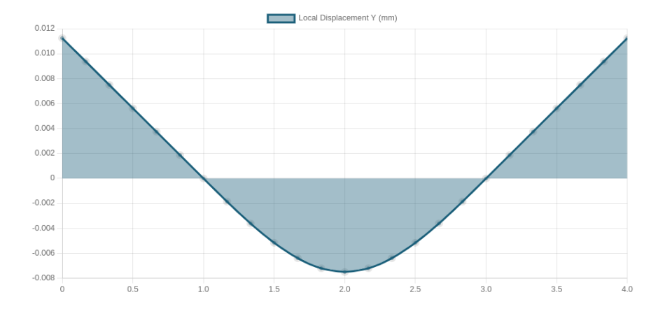
- Allowable mid-span deflection: ≤ L/500 under service loads → ≤ 12 mm on a 6 m span.
- Mass budget per metre: ≈ 4.0 kg/m laminate (2 mm wall, ρ≈1600 kg/m³) → ~76–80 kg for a 19 m tube incl. joins/coatings contingency.
- Laminate schedule/plan: Eight plies total of 3K 200 gsm plain-weave tape (100 mm width) applied by spiral wrap: 4× CW + 4× CCW, ~75% overlap (25 mm step) for ~2.0 mm consolidated wall; wet lay-up with high-temp epoxy; consolidation via compression wrap + thermal expansion of the 400 mm Al mold; cure ~120 °C per resin datasheet.
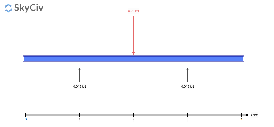
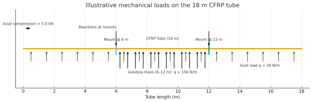
Diagram showing Axial compression (~5 kN), distributed lateral gust load (~30 N/m) along the whole tube, added gondola mass between 6–12 m (~150 N/m), plus the two mounts (reactions) at 6 m and 12 m.
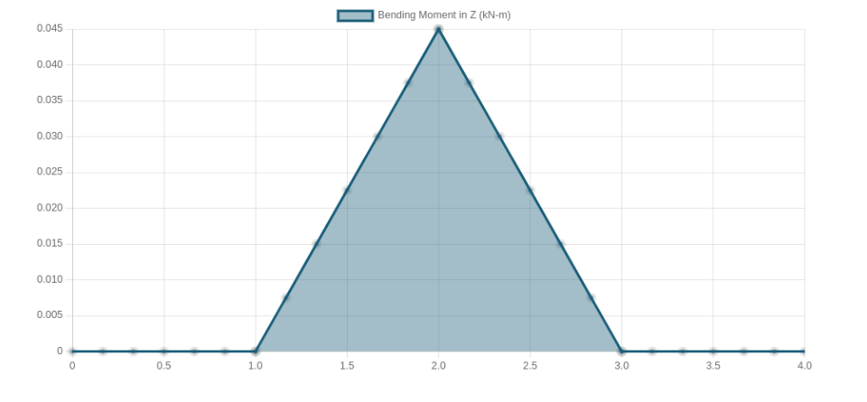
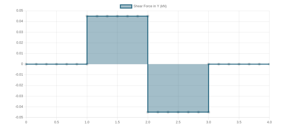
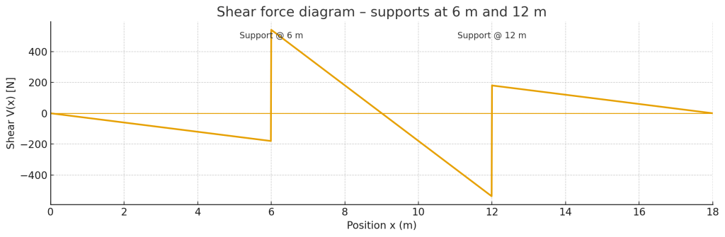
Plots of shear and bending moment diagrams for our loads:
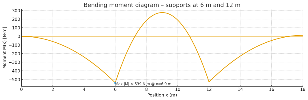
Anyway, the purpose of this tube stays the same: it’s our airship keel and doubles as a vectoring intake manifold so we can steer in 3D without classic elevators/rudders. Physics did smack us with a reality check: using these intakes for forward motion comes with ~25–35% efficiency penalty (credits to Chris Drake for smacking hard!). So the plan is to use them primarily for slow‑speed direction changes and yaw/roll/pitch control, and only lean on them for forward‑thrust assist when really needed.
Shopping, rolling, and a friendly metal shop
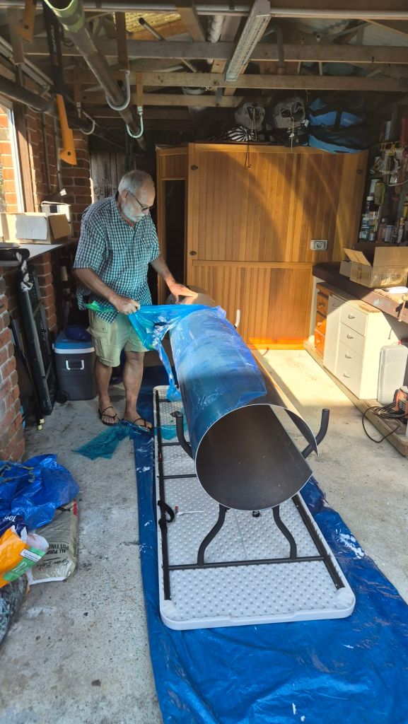
The initial plan was a simple aluminium sheet to form a mandrel:
- Sheet SKU 100115
Material: 5005 H34, 2.0 × 1200 × 2400 mm (Mill Finish)
https://shop.capral.com.au/100115/
Then I spoke with Richard & Paula at Brisbane Metal Form (https://brisbanemetalform.com.au/). They not only gave me a good price but also offered to roll the sheet into a tube.
On Thu, 21 Aug 2025, 2:55 pm, Richard Shilling wrote:
All up cost including GST: $286.00
Thanks Richard!
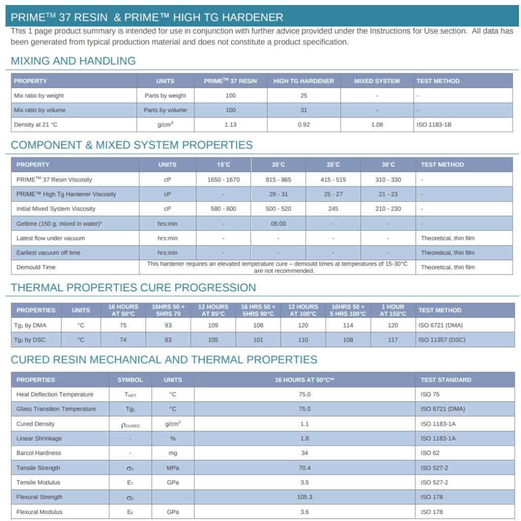
HT epoxy & cure profile
Next stop: Gurit PRIME™ 37 high‑temperature system via a local supplier (smooth process).
- Datasheet: https://www.gurit.com/wp-content/uploads/bsk-pdf-manager/2022/08/PRIME-37-1.pdf
- Invoice: [insert PDF or screenshot]
Target cure from the datasheet is 150 °C for 1 h (post‑cure), but there’s also a 100 °C for 12 h pathway to achieve required strength – handy in case we can’t hit 150 °C on the nose.
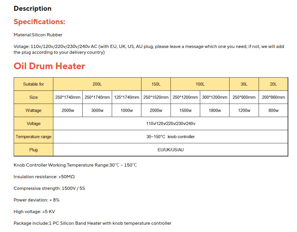
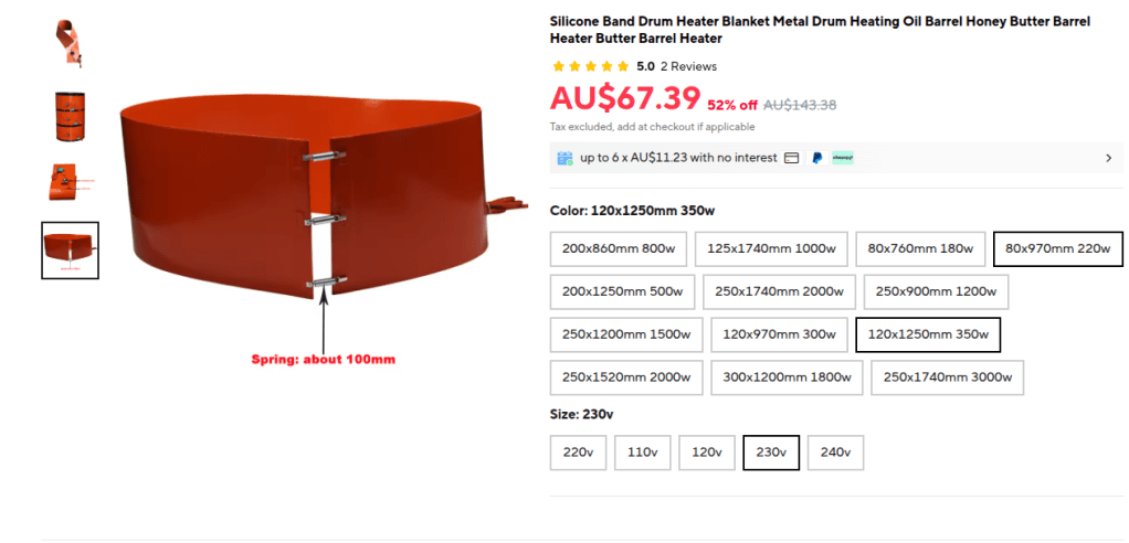
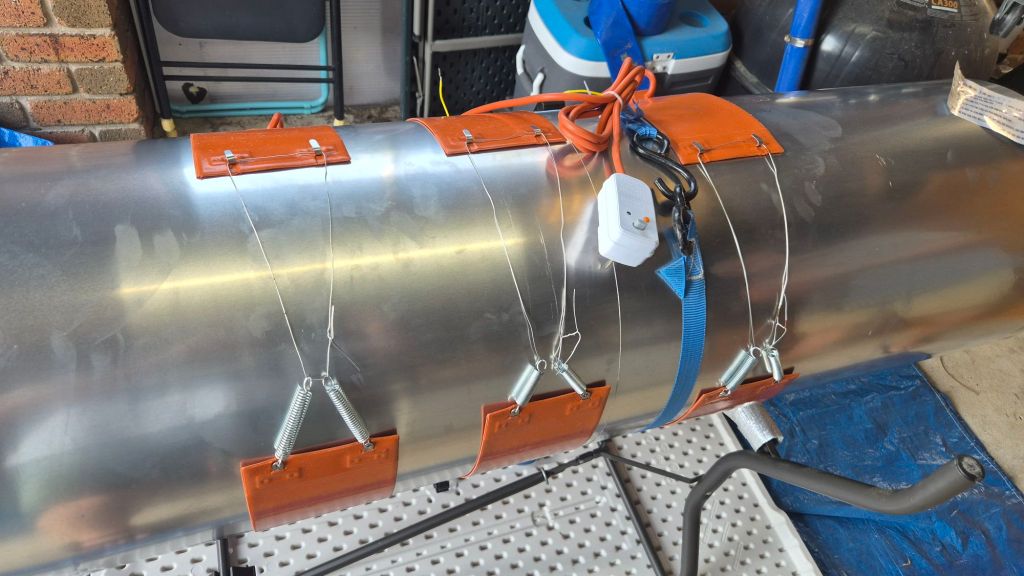
Chatting with Vilem & Martin, Martin suggested silicone drum‑heater belts mounted inside the aluminium mandrel to heat the laminate from within. We went with these:
Silicone Band Drum Heater Blanket (120 × 970 mm, 300 W)
https://www.aliexpress.com/item/1005006949643440.html
Initial order: 6 × 120×970 mm / 300 W – for testing and initial installation too.
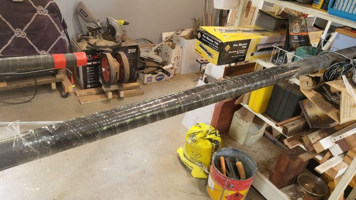
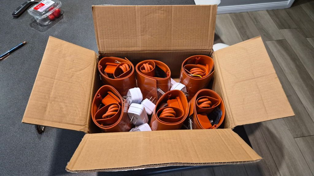
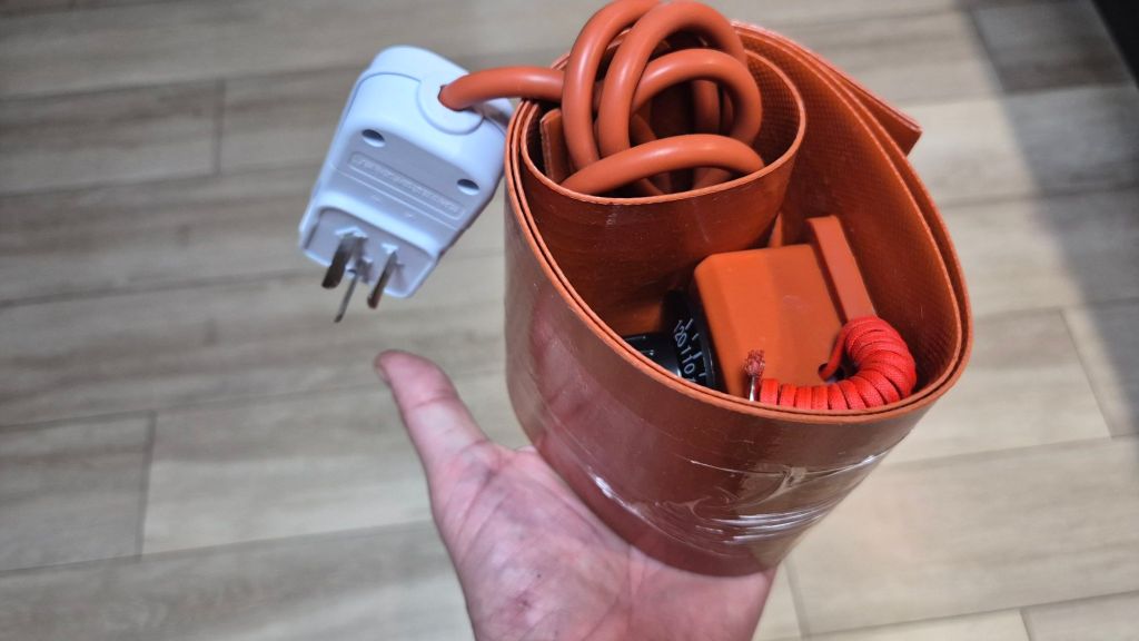
Package arrived in a week time
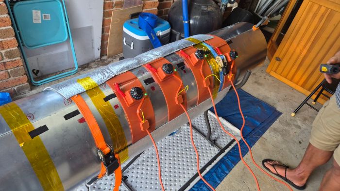
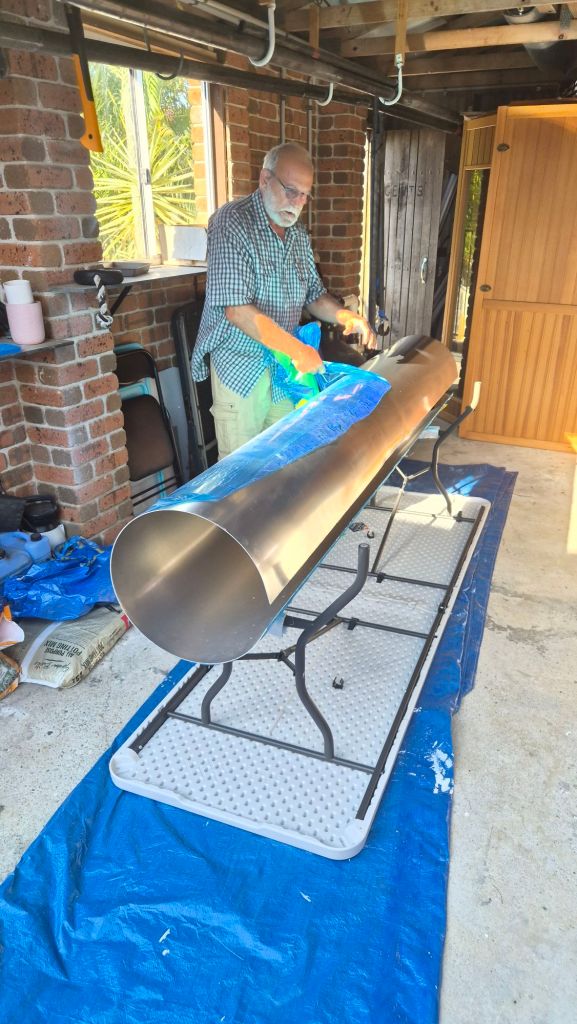
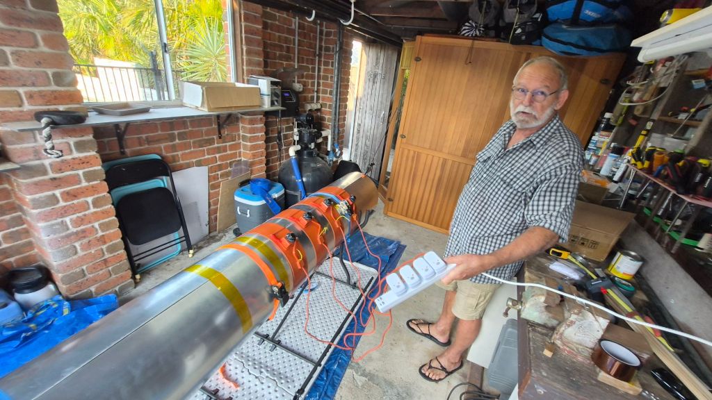
Test day with Serge — setup & goals
Huge thanks to Serge for jumping in on Sunday afternoon! We set goals:
- Check that the belts actually heat and we can operate them safely.
- Characterise heat‑up speed, max temperature, and edge losses.
- Verify thermal expansion of the aluminium mandrel (critical for our process: expand under heat to press the CF wrap; shrink to release after cure).
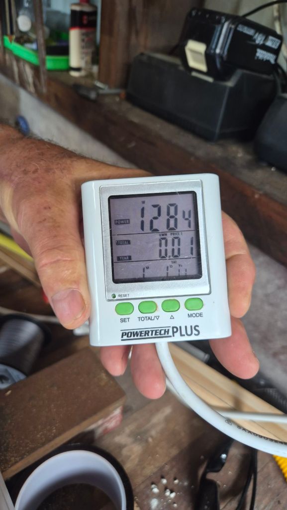
- Log power draw.
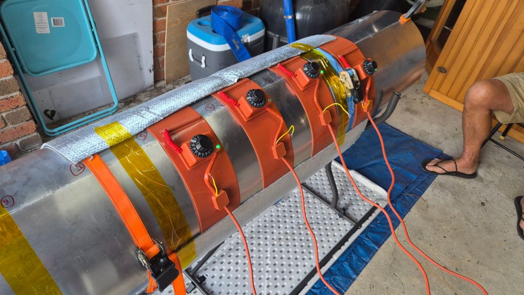
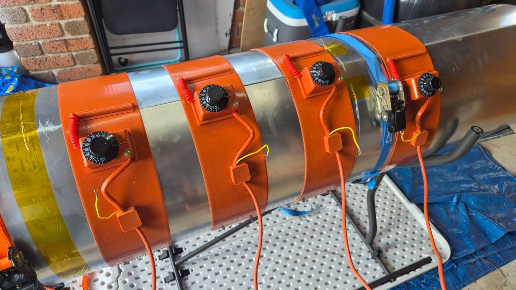
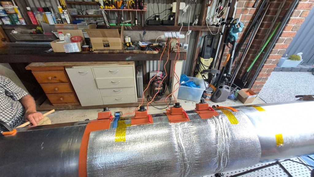
Setup:
- Tube set horizontally.
- Four belts, mounted vertically inside the tube, spaced ~100 mm apart (test configuration).
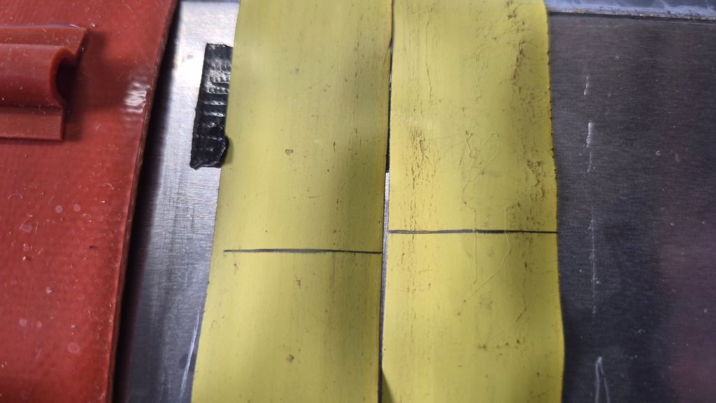
- Temperature points marked on the outside, T0…T6.
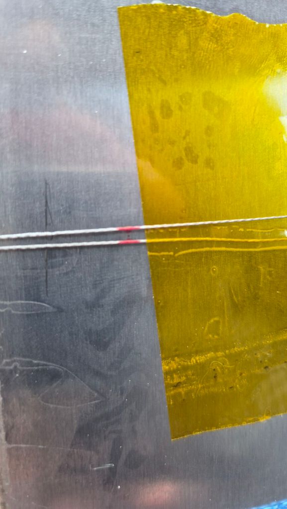
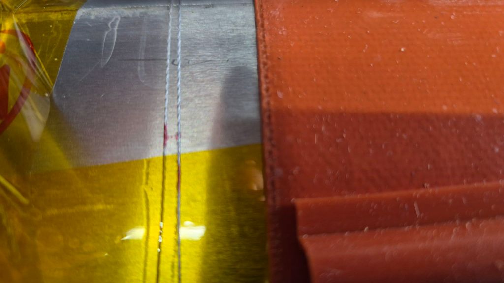
- A textile line (tight loop) around the circumference to track expansion.
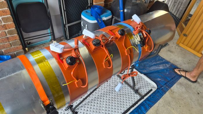
Ambient was ~27 °C, mostly still air with the occasional tiny gust.
CF Tube Heating Log (OCR + Stats)
| time | T0 | T1 | T2 | T3 | T4 | T5 | T6 | minutes | mean | min | max | spread |
| 4:37 | 28 | 28 | 28 | 28 | 28 | 28 | 28 | 0 | 28 | 28 | 28 | 0 |
| 4:46 | 29 | 32 | 31 | 35 | 32 | 30 | 29 | 9 | 31.1 | 29 | 35 | 6 |
| 4:52 | 35 | 38 | 39 | 40 | 40 | 35 | 15 | 15 | 34.6 | 15 | 40 | 25 |
| 5:09 | 77 | 83 | 97 | 102 | 89 | 67 | 55 | 32 | 81.4 | 55 | 102 | 47 |
| 5:21 | 77 | 77 | 95 | 104 | 93 | 68 | 56 | 44 | 81.4 | 56 | 104 | 48 |
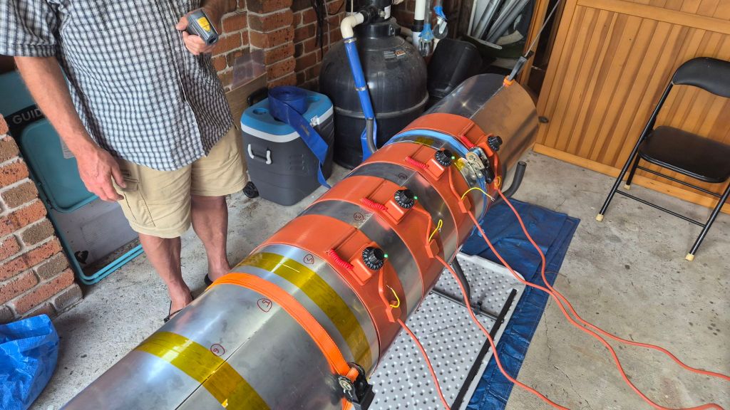
Early facepalm, then good data
For about 30 minutes we “saw” almost no temperature rise. Then Serge touched the tube and went: “It’s hot!”. Turns out our IR thermometer (https://www.bunnings.com.au/matador-surface-infrared-thermometer_p0276145) can’t read polished aluminium properly (emissivity!) so our numbers were… artistic.
We slapped black tape over the measurement spots and instantly got sane readings. We also added front & rear end‑caps to reduce airflow, plus a thermal blanket to curb losses.
Results & takeaways
1) 150 °C vs 120 °C reality
The belt listing says up to 150 °C, but the knob tops out at 120 °C. That’s okay for now – PRIME 37 allows 100 °C × 12 h, so we can still hit strength targets; we’ll just run a longer cycle while we sort the 150 °C option.
2) Edge losses are real
We observed a big temperature drop at the tube edges. Plan: add two more belts near the sides (i.e., circumferentially offset) to flatten the temperature gradient where we’re working.
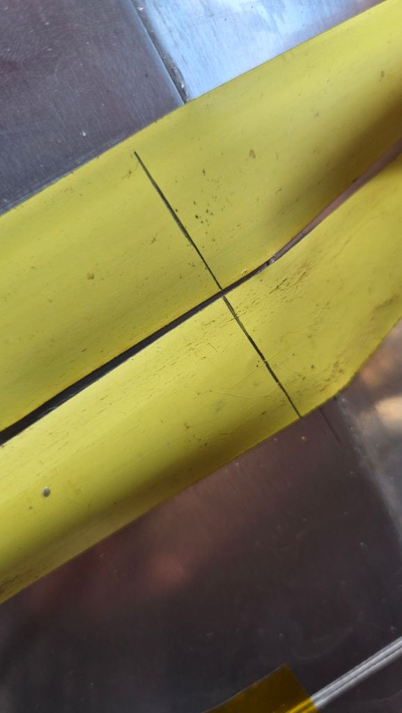
3) Thermal expansion: measured vs theory
We recorded ~7 mm increase using the textile loop. For reference, theoretical circumference expansion for 5005‑H34 Al (α ≈ 23×10⁻⁶/°C) from 26 °C → 100 °C (ΔT = 74 °C) on a Ø 400 mm tube is:
- Circumference C = π·D ≈ 1200.00 mm
- Fractional expansion = α·ΔT = 23e‑6 × 74 ≈ 0.001702
- ΔC = C × 0.001702 ≈ 2.14 mm → ΔD ≈ 0.68 mm
So our 7 mm observation was >3× theoretical ΔC and ~10× theoretical ΔD. Likely causes: ovalisation of the tube under uneven heating, local hotspots, textile heat-shrink, or measurement slack in the textile loop. We’ll re‑run with full 6‑belt coverage, rotational averaging (see next point), and a steel band gauge.
4) Top vs bottom gradient
Horizontal layup showed clear temperature stratification (hotter top, cooler bottom). We’ll need to add a slow back‑and‑forth 180° rotation during soak to average it out.
5) Join the seam
The rolled‑sheet seam is wobbly. We need to stiffen/join both longitudinal edges:
- Welded seam: stiff, permanent, but reduces interior access later.
- Mechanical seam: long backing strip + countersunk fasteners; keeps future access but needs careful heat‑path design.
We’ll trial the mechanical seam first.
What’s next
- Order two more belts (longer size: 120 × 1250 mm, 350 W) for edge coverage.
- Adhesively bond belt mounts and add thermal shields under each.
- Confirm with the vendor why we saw 120 °C limit on a 150 °C‑rated unit.
- Add slow rotation during soak and repeat the expansion test with a proper band gauge.
- Decide seam strategy (mechanical first, welded if needed).
Huge thanks to Serge for all the help and patience – and to Richard & Paula for rolling the tube so quickly.