Grond: an update on our Phase II keel-tube development

It has been a while, but we are moving ahead again.

For Phase II we need to develop two long carbon-fibre keel tubes: roughly 19 m long and 400 mm in diameter. They are meant to do much more than look tidy. They are the backbone of the airship: carrying the gondola and cross-beam loads, helping join the two hulls together, and eventually giving us a home for the keel-vectoring hardware.

That makes the tubes one of the big make-or-break pieces of the project. It is also a direct continuation of our Phase I tube adventures. Back then we learned how much work hides behind a nice-looking carbon tube: winding, heat, release, curing, a bit of stubbornness, and plenty of testing. Phase II is the same story – just with a rather more serious tube.
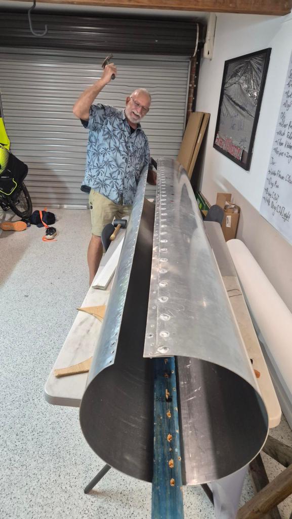
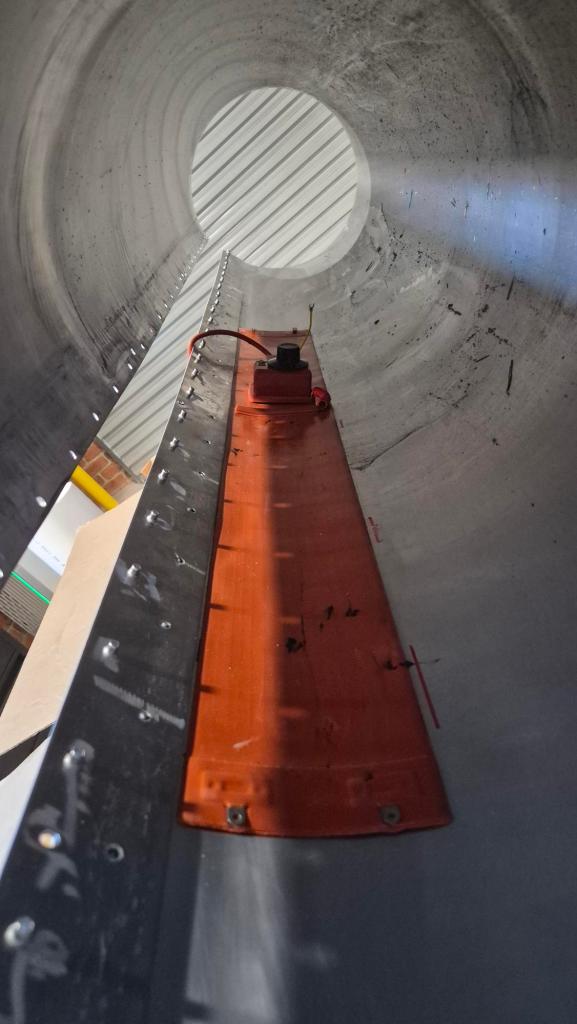
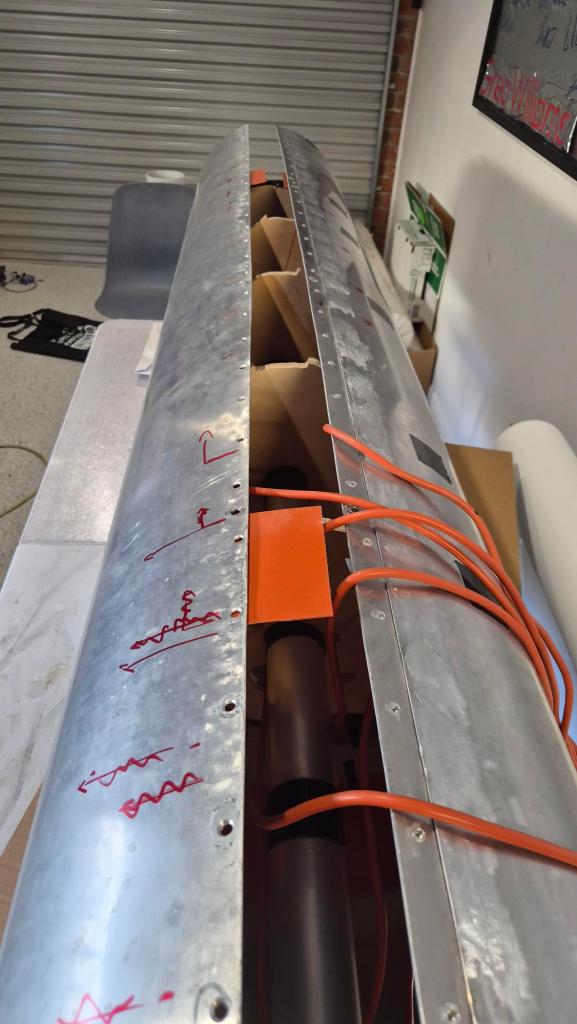
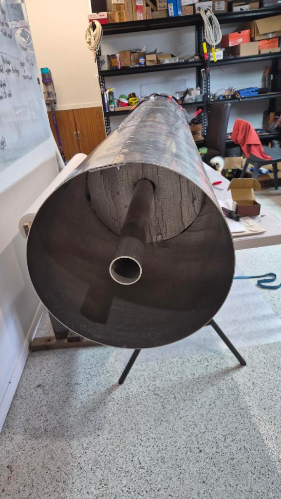
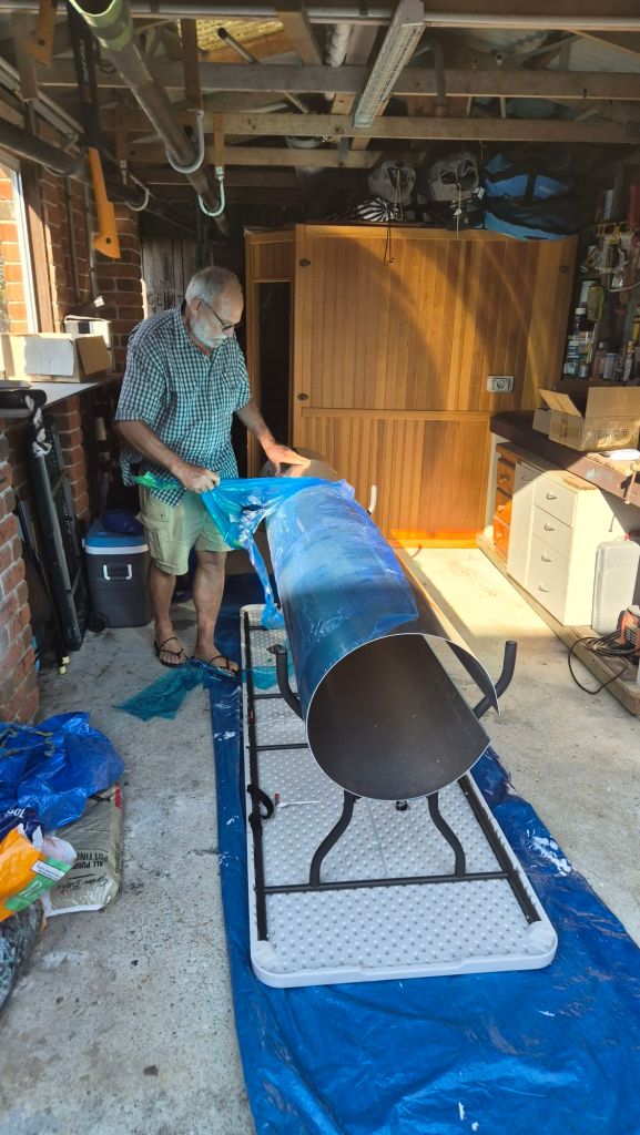
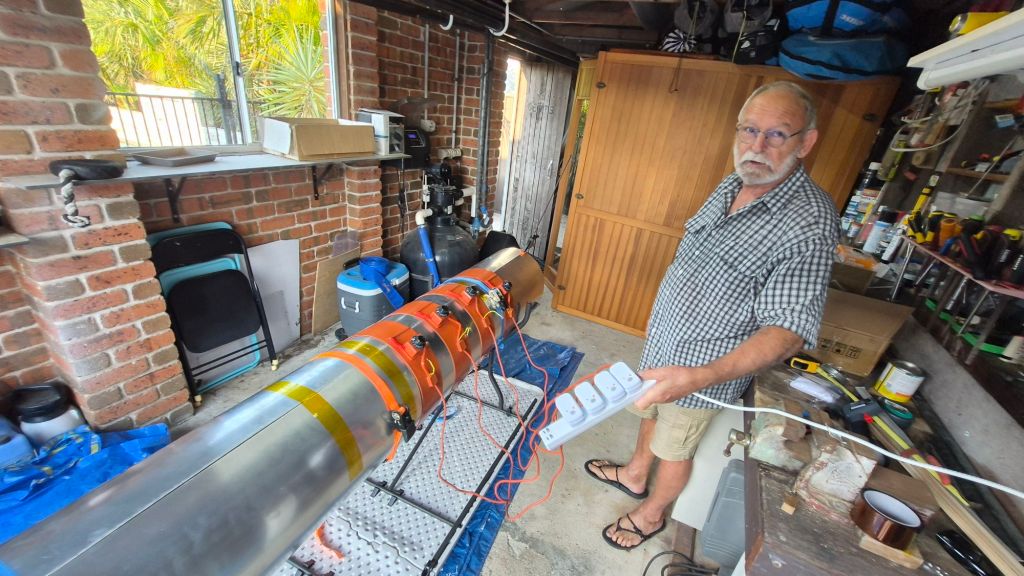
The Grond mould open in the workshop

How light does it need to be?

The first planning placeholder was about 76 kg per keel, based on a 2 mm shell-equivalent wall. We would very much like to do better than that. Our current first-pass structural screen uses a 60 kg keel as a useful target, which corresponds to roughly a 1.58 mm uniform-wall equivalent before the real reinforcement zones, joins and fittings are designed.

We have now gone back through the simplified lift and load picture rather than just waving our hands at a very long tube. In the 650 kg total-lift sensitivity case, after allowing for the envelope, a 60 kg keel, a 10 kg tip assembly and a 5 kg tail-vector assembly, the two main cross-beam stations per keel carry approximately:

  • 61 kg at the front cross-beam;
  • 135 kg at the rear cross-beam.

The first global beam check is actually encouraging. It gives about 1.29 kN m of maximum bending moment at the rear cross-beam, an indicative 6.6 MPa outer-fibre bending stress and around 14 mm of relative deflection under the idealised static case. The important word there is first. It does not yet prove a flight-ready tube. The tricky work is still local reinforcement around the cross-beams, nacelles, joins and anything that wants to put a hole through our lovely tube. Gusts, thrust, handling and fatigue still need their own checks – but it is a much better place to start than a guess.
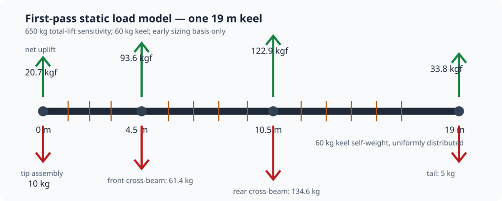
Simplified first-pass keel static-load diagram

Back to the mould

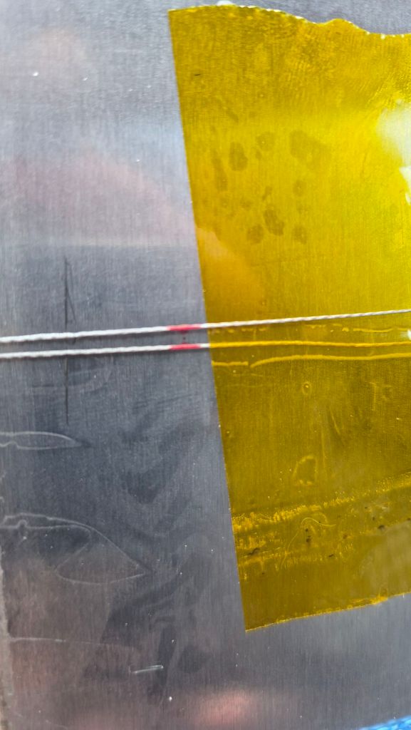
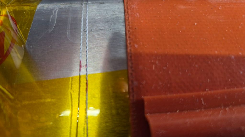
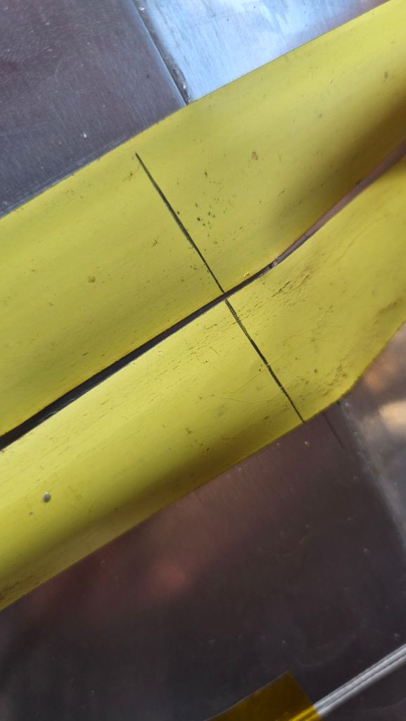
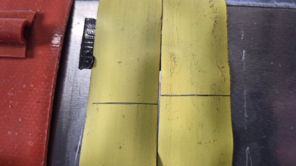
The manufacturing idea is familiar from Phase I. We will wrap carbon fibre around an aluminium mould, wet it with high-temperature epoxy, bring the cure zone up to roughly 100 C, and then let the part cure before cooling the mould back down. The mould is protected with Kapton tape and high-temperature release wax; the hope is that, after cooling, the finished tube lets go cleanly enough to slide the tooling along and continue the process towards a continuous keel.
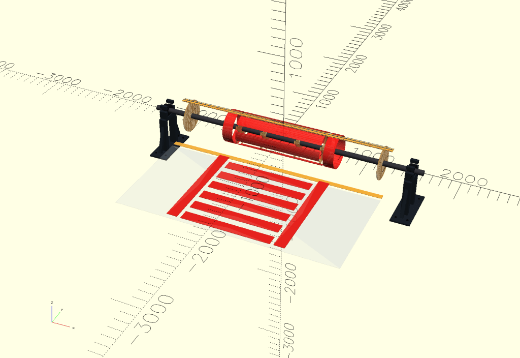
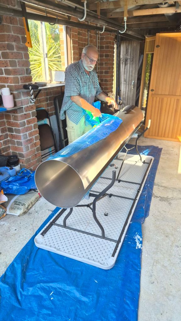
That is the theory. The workshop version is a 2.5 m long aluminium mould section made from a rolled 2500 x 1200 x 3 mm sheet. Its resulting outside diameter is about 382 mm, close enough to the planned 400 mm keel to make it a useful and honest process test.
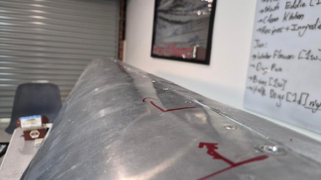
The rolled aluminium mould section

Rather than welding the rolled sheet permanently shut, we made it serviceable. An internal 60 mm aluminium seam strap is spot-welded along one side, then secured with nutserts and countersunk fasteners on the other. That means we can open the mould to get at heaters, wiring and partitions instead of turning a small mistake into a large aluminium paperweight.

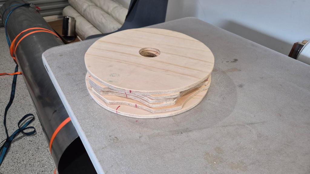
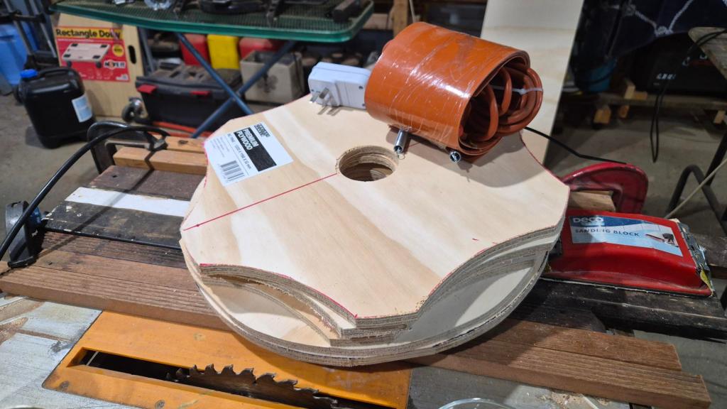
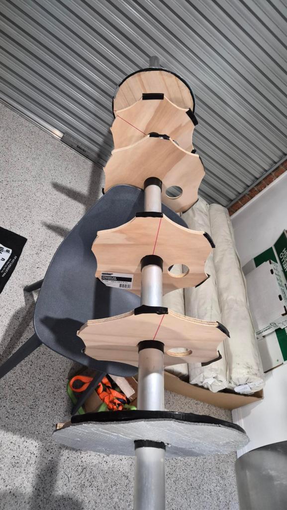
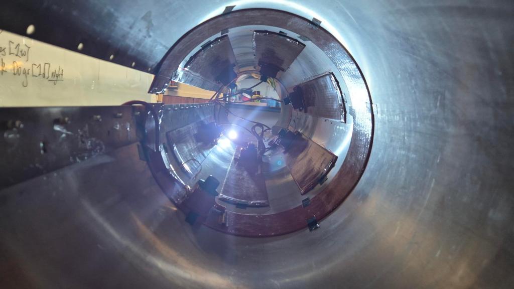
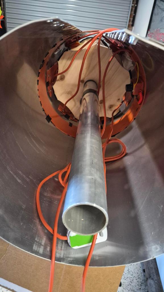
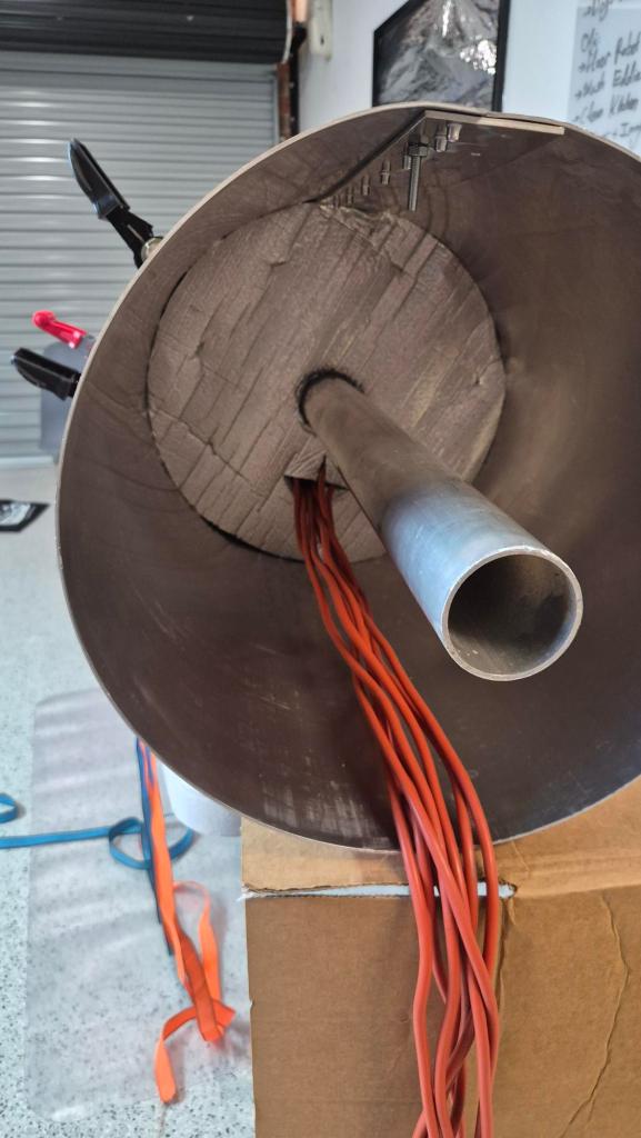
Inside are six plywood partitions, a central 60 mm axle and the beginnings of a spinning/winding jig. It is all there to keep the mould round, support it while we work, and leave us room to improve the process as we learn.

Making it hot

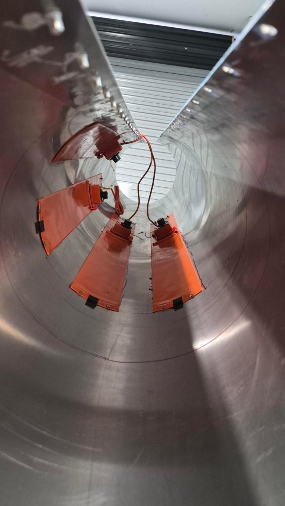
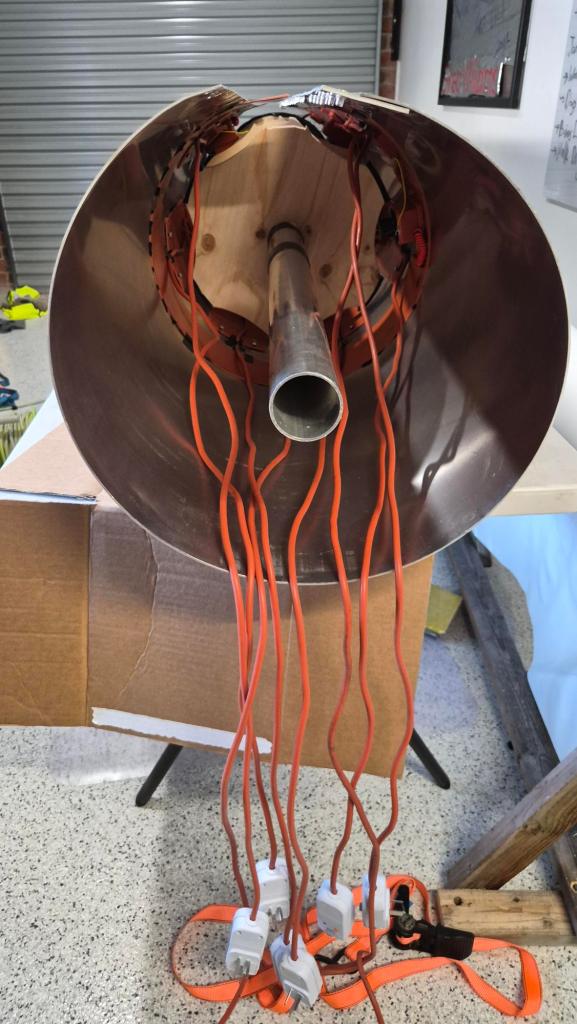
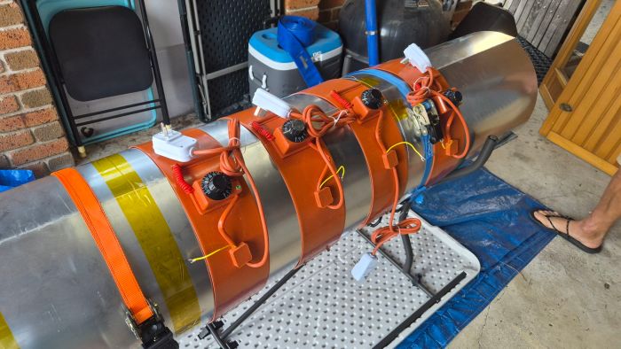
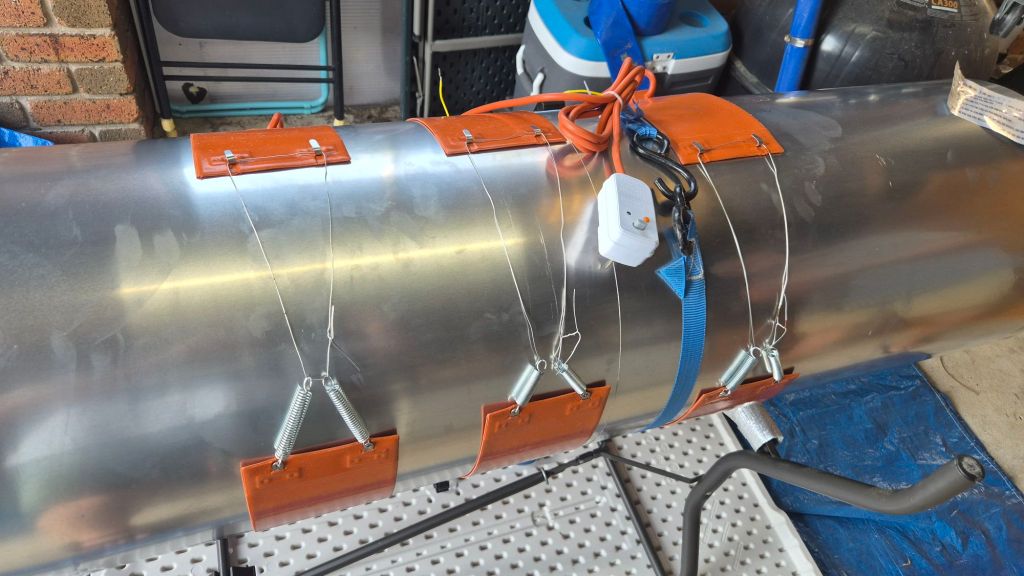
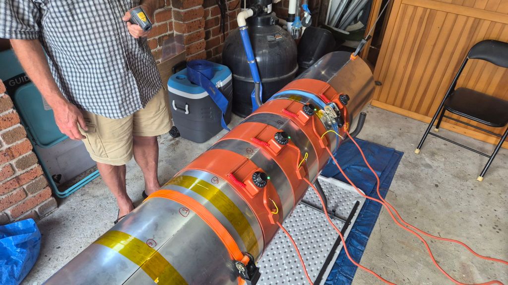
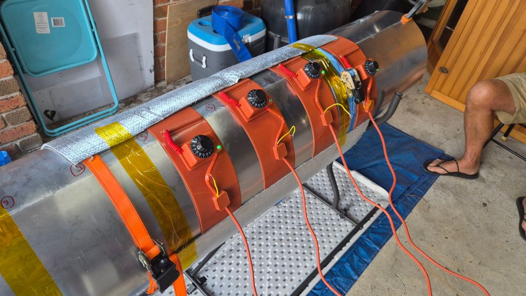
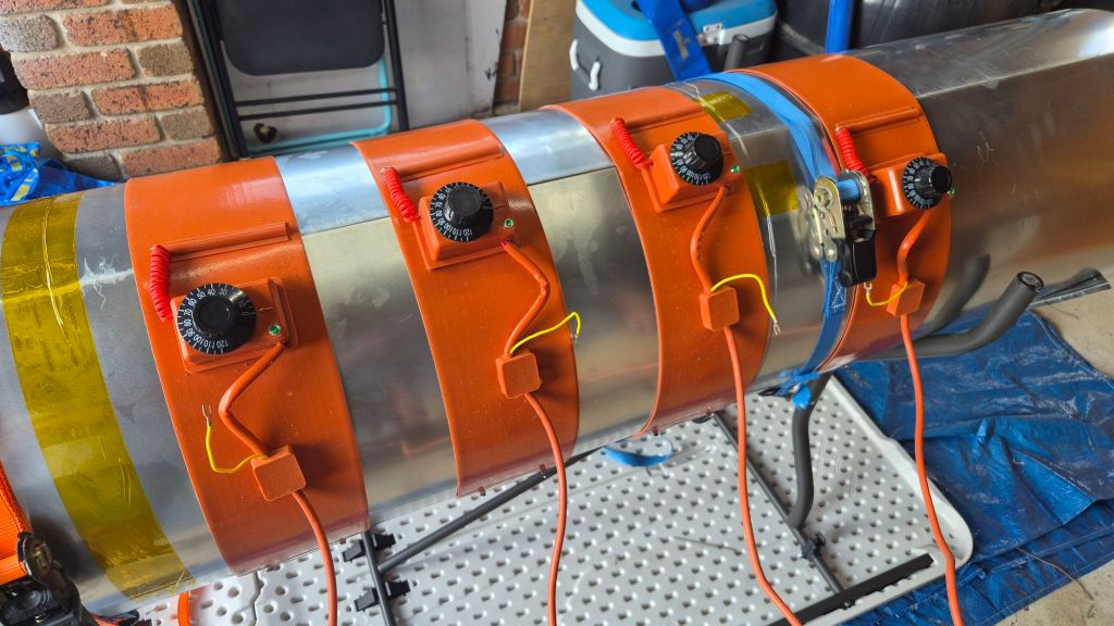
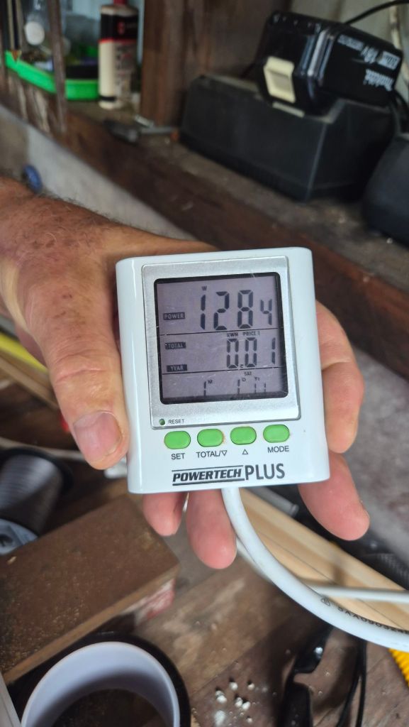
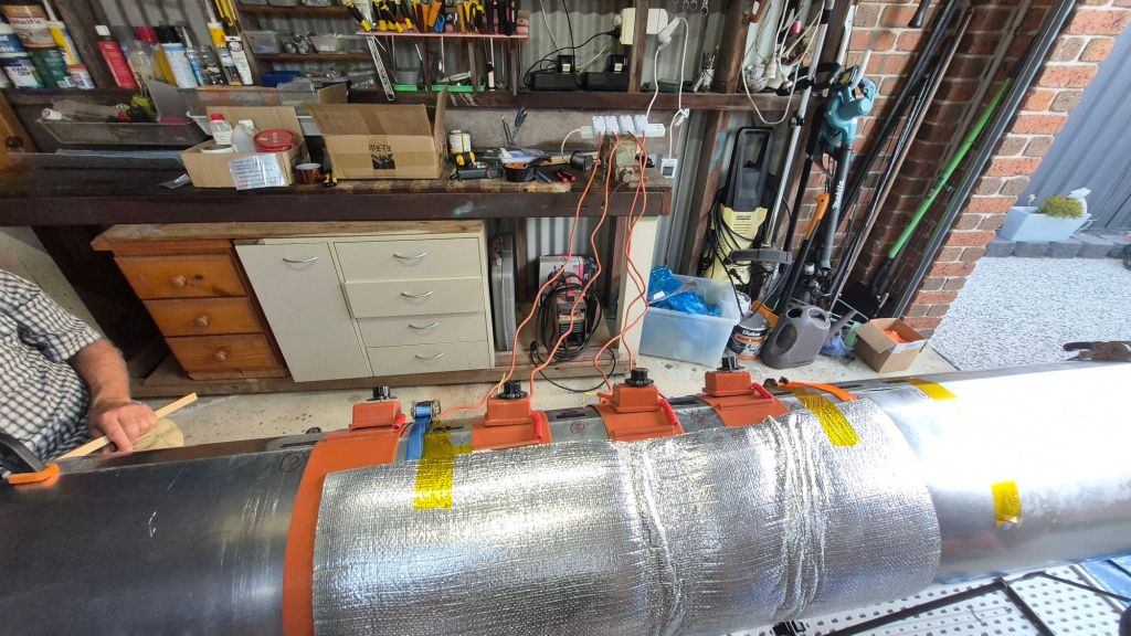
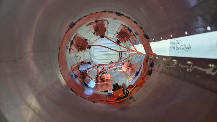
The cure is a big part of the experiment, so the mould is being fitted with flexible heater belts inside the aluminium shell. The plan is six axial belts (120 x 1000 mm, 300 W each), plus two belts around the circumference near the ends of the working zone (about 400 W each). At full power that is a potential 2.6 kW, so this is definitely not a casual plug-it-into-any-old 10 A workshop socket job.

One heater has already survived its first small test: after a 24 h adhesive cure, it stayed attached through an 80 C, one-hour heat run. Next we will fit the rest, check clearance around the partitions, and map the real temperature across the mould. The thermometer on a heater is not the same thing as knowing what the aluminium (and later the resin) are actually doing.
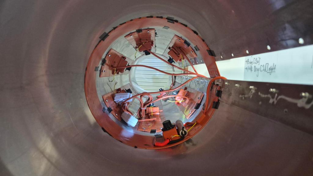
Inside Grond: heater layout, partitions and wiring

The people and the name

We started with the rolled aluminium sheet. Vilem helped weld the seam strap and fit the nutserts; Serge helped with the partitions; Kristian took on the less glamorous but very necessary clearing and sanding work. Once it was all coming together, it looked rather spectacular in the workshop.
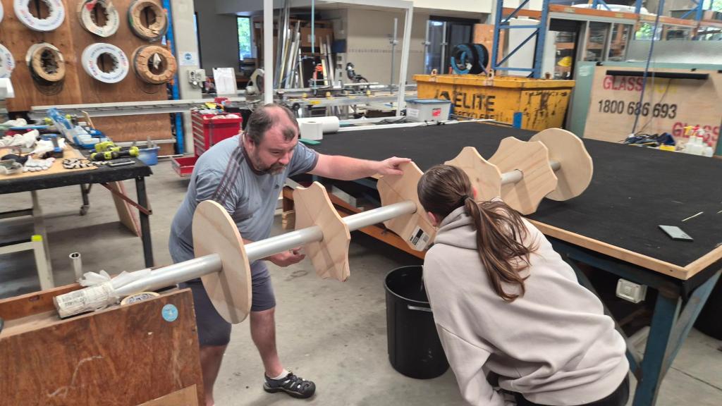
Building the plywood partitions

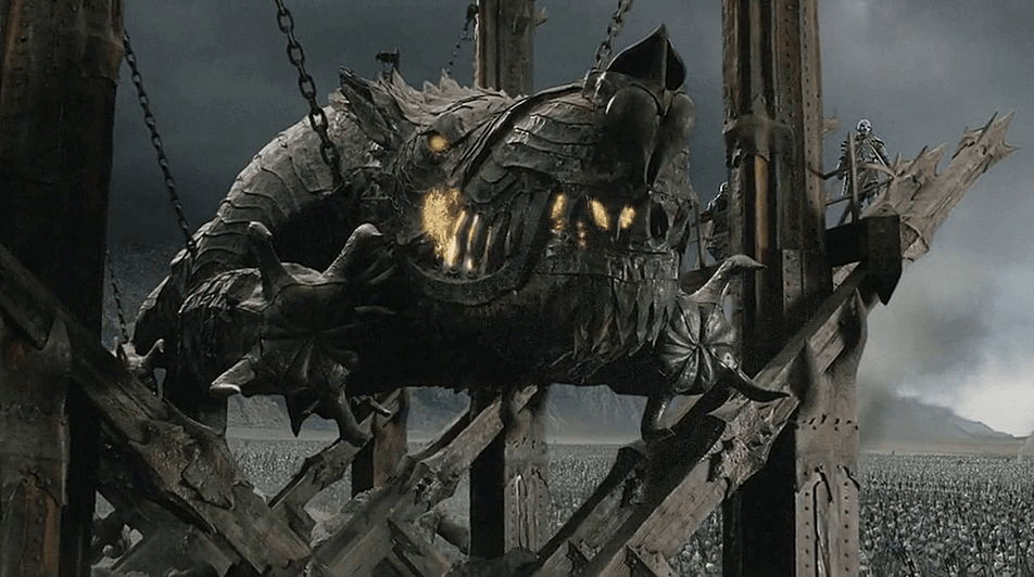
Serge also suggested that the mould needed a name. That felt correct. We have called it Grond – a nod to Tolkien’s famously formidable battering ram. Hopefully ours will be slightly friendlier to operate, and much less interested in knocking down city gates.
What happens next

First we finish the heater installation, prove that the mould warms evenly and sort out the practical winding support. Then come carbon layup trials, measured mass per metre, and reinforcement experiments around the real load stations.

The end goal is still a continuous 19 m keel tube, but we are deliberately getting there one workshop-sized lesson at a time. That is how the Phase I tube work got us this far, and it is how Grond will earn its name.

Gallery
CF Tubes – Phase II: Heating Rig Test & First Wins

Over the weekend we finally achieved something worth reporting!

As part of our airship design and Phase II scale‑up (see our Carbon Fiber Tube Sizing conversation around the H2Use project), we need to develop a new 19 m long, Ø 400 mm carbon‑fiber tube that can withstand the loads and deflections defined in our sizing study.

Specs recap:

  • Target axial load: 5 kN service (conservative) with very large margin vs. Euler buckling on 6 m effective spans.
  • Bending stiffness (EI): ≈ 3.47 × 10⁶ N·m² (Ø 400 mm, wall 2 mm, E≈70 GPa).
  • Safety factors: Global buckling ≥ 3, local wall buckling ≥ 2, bonded joints ≥ 2.5 (prototype targets).
  • Allowable mid-span deflection: ≤ L/500 under service loads → ≤ 12 mm on a 6 m span.
  • Mass budget per metre: ≈ 4.0 kg/m laminate (2 mm wall, ρ≈1600 kg/m³) → ~76–80 kg for a 19 m tube incl. joins/coatings contingency.
  • Laminate schedule/plan: Eight plies total of 3K 200 gsm plain-weave tape (100 mm width) applied by spiral wrap: 4× CW + 4× CCW, ~75% overlap (25 mm step) for ~2.0 mm consolidated wall; wet lay-up with high-temp epoxy; consolidation via compression wrap + thermal expansion of the 400 mm Al mold; cure ~120 °C per resin datasheet.

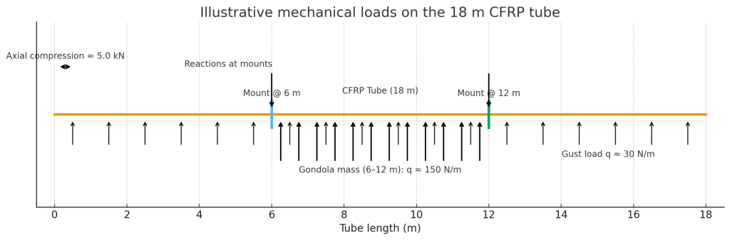
Diagram showing Axial compression (~5 kN), distributed lateral gust load (~30 N/m) along the whole tube, added gondola mass between 6–12 m (~150 N/m), plus the two mounts (reactions) at 6 m and 12 m.

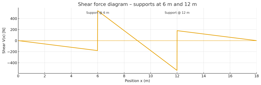
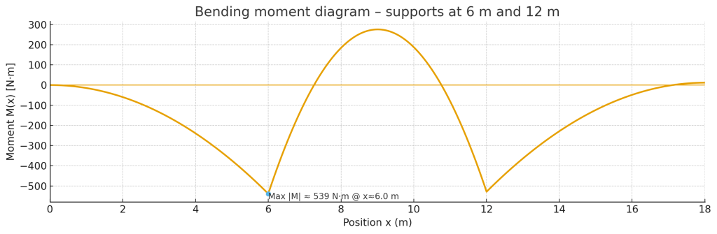
Plots of shear and bending moment diagrams for our loads:

Anyway, the purpose of this tube stays the same: it’s our airship keel and doubles as a vectoring intake manifold so we can steer in 3D without classic elevators/rudders. Physics did smack us with a reality check: using these intakes for forward motion comes with ~25–35% efficiency penalty (credits to Chris Drake for smacking hard!). So the plan is to use them primarily for slow‑speed direction changes and yaw/roll/pitch control, and only lean on them for forward‑thrust assist when really needed.

Shopping, rolling, and a friendly metal shop

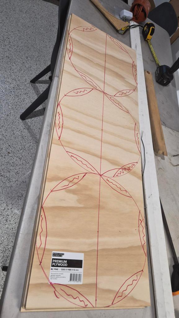
The initial plan was a simple aluminium sheet to form a mandrel:

Then I spoke with Richard & Paula at Brisbane Metal Form (https://brisbanemetalform.com.au/). They not only gave me a good price but also offered to roll the sheet into a tube.

On Thu, 21 Aug 2025, 2:55 pm, Richard Shilling wrote:
All up cost including GST: $286.00
Thanks Richard!

HT epoxy & cure profile

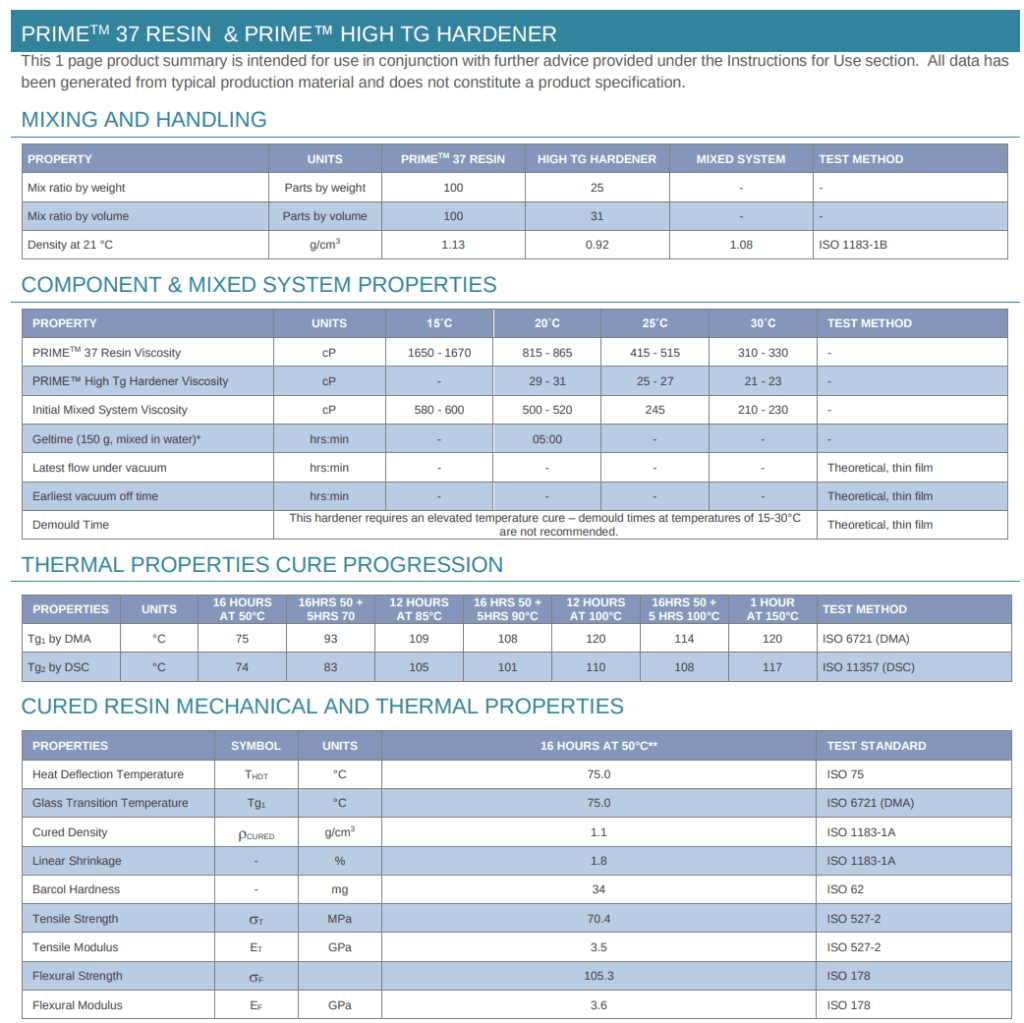
Next stop: Gurit PRIME™ 37 high‑temperature system via a local supplier (smooth process).

Target cure from the datasheet is 150 °C for 1 h (post‑cure), but there’s also a 100 °C for 12 h pathway to achieve required strength – handy in case we can’t hit 150 °C on the nose.

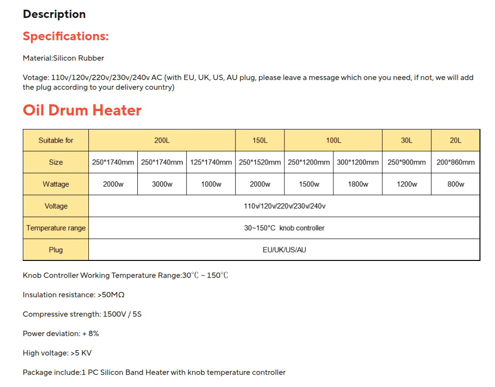
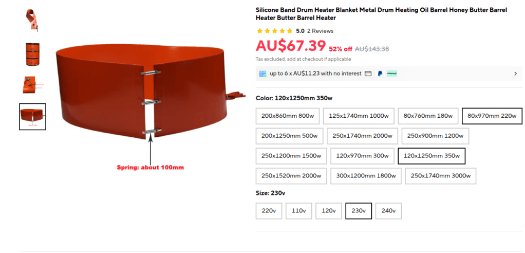
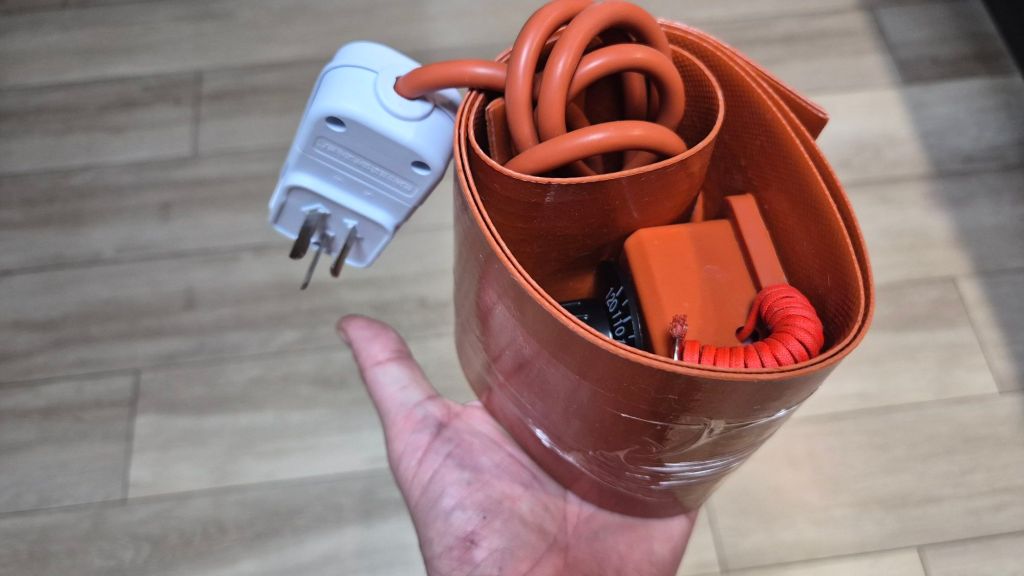
Chatting with Vilem & Martin, Martin suggested silicone drum‑heater belts mounted inside the aluminium mandrel to heat the laminate from within. We went with these:
Silicone Band Drum Heater Blanket (120 × 970 mm, 300 W)
https://www.aliexpress.com/item/1005006949643440.html

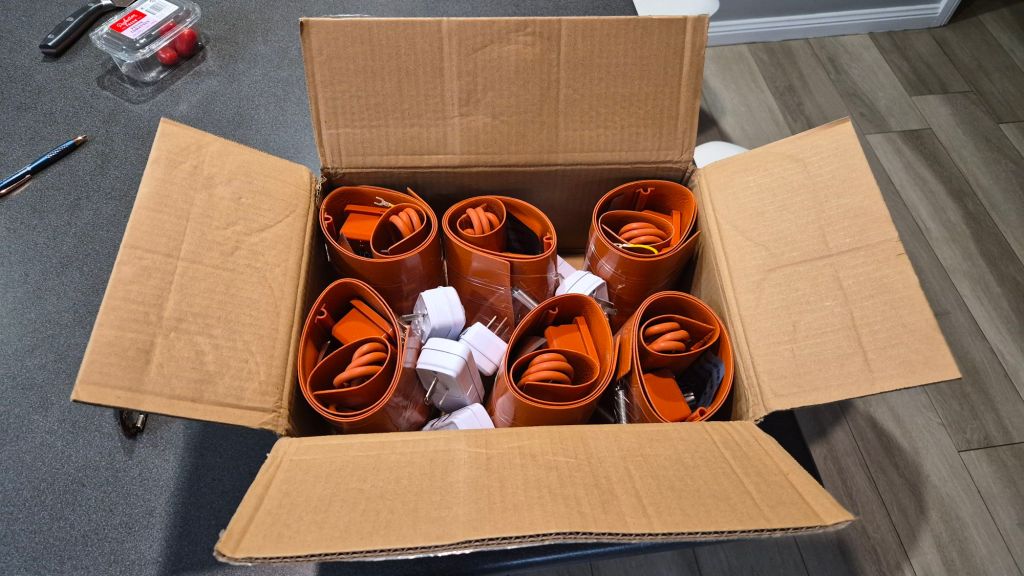
Initial order: 6 × 120×970 mm / 300 W – for testing and initial installation too.

Package arrived in a week time

Test day with Serge — setup & goals

Huge thanks to Serge for jumping in on Sunday afternoon! We set goals:

  • Check that the belts actually heat and we can operate them safely.
  • Characterise heat‑up speed, max temperature, and edge losses.
  • Verify thermal expansion of the aluminium mandrel (critical for our process: expand under heat to press the CF wrap; shrink to release after cure).
  • Log power draw.

Setup:

  • Tube set horizontally.
  • Four belts, mounted vertically inside the tube, spaced ~100 mm apart (test configuration).
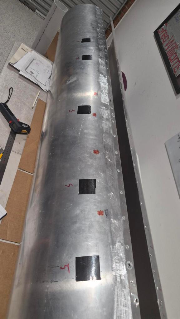
  • Temperature points marked on the outside, T0…T6.
  • A textile line (tight loop) around the circumference to track expansion.

Ambient was ~27 °C, mostly still air with the occasional tiny gust.

CF Tube Heating Log (OCR + Stats)

timeT0T1T2T3T4T5T6minutesmeanminmaxspread
4:372828282828282802828280
4:4629323135323029931.129356
4:52353839404035151534.6154025
5:097783971028967553281.45510247
5:217777951049368564481.45610448

Early facepalm, then good data

For about 30 minutes we “saw” almost no temperature rise. Then Serge touched the tube and went: “It’s hot!”. Turns out our IR thermometer (https://www.bunnings.com.au/matador-surface-infrared-thermometer_p0276145) can’t read polished aluminium properly (emissivity!) so our numbers were… artistic.

We slapped black tape over the measurement spots and instantly got sane readings. We also added front & rear end‑caps to reduce airflow, plus a thermal blanket to curb losses.

Results & takeaways

1) 150 °C vs 120 °C reality
The belt listing says up to 150 °C, but the knob tops out at 120 °C. That’s okay for now – PRIME 37 allows 100 °C × 12 h, so we can still hit strength targets; we’ll just run a longer cycle while we sort the 150 °C option.

2) Edge losses are real
We observed a big temperature drop at the tube edges. Plan: add two more belts near the sides (i.e., circumferentially offset) to flatten the temperature gradient where we’re working.

3) Thermal expansion: measured vs theory
We recorded ~7 mm increase using the textile loop. For reference, theoretical circumference expansion for 5005‑H34 Al (α ≈ 23×10⁻⁶/°C) from 26 °C → 100 °C (ΔT = 74 °C) on a Ø 400 mm tube is:

  • Circumference C = π·D ≈ 1200.00 mm
  • Fractional expansion = α·ΔT = 23e‑6 × 74 ≈ 0.001702
  • ΔC = C × 0.001702 ≈ 2.14 mm → ΔD ≈ 0.68 mm

So our 7 mm observation was >3× theoretical ΔC and ~10× theoretical ΔD. Likely causes: ovalisation of the tube under uneven heating, local hotspots, textile heat-shrink, or measurement slack in the textile loop. We’ll re‑run with full 6‑belt coverage, rotational averaging (see next point), and a steel band gauge.
4) Top vs bottom gradient
Horizontal layup showed clear temperature stratification (hotter top, cooler bottom). We’ll need to add a slow back‑and‑forth 180° rotation during soak to average it out.

5) Join the seam
The rolled‑sheet seam is wobbly. We need to stiffen/join both longitudinal edges:

  • Welded seam: stiff, permanent, but reduces interior access later.
  • Mechanical seam: long backing strip + countersunk fasteners; keeps future access but needs careful heat‑path design.

We’ll trial the mechanical seam first.

What’s next

  • Order two more belts (longer size: 120 × 1250 mm, 350 W) for edge coverage.
  • Adhesively bond belt mounts and add thermal shields under each.
  • Confirm with the vendor why we saw 120 °C limit on a 150 °C‑rated unit.
  • Add slow rotation during soak and repeat the expansion test with a proper band gauge.
  • Decide seam strategy (mechanical first, welded if needed).

Huge thanks to Serge for all the help and patience – and to Richard & Paula for rolling the tube so quickly.

CF Tubes Reinforcement & Testing

Since the beginning of our carbon fibre (CF) tube manufacturing journey, one question has lingered in my mind—how strong are these tubes, really? We knew they would be lightweight and durable, but with their role in critical load-bearing parts like our EDF (Electric Ducted Fan) intakes and 3D thruster mounts, we had to be sure. Initial tests and assemblies exposed the reality: some of the early designs couldn’t handle the stress. A few unfortunate failures under load made it clear we needed a stronger solution.

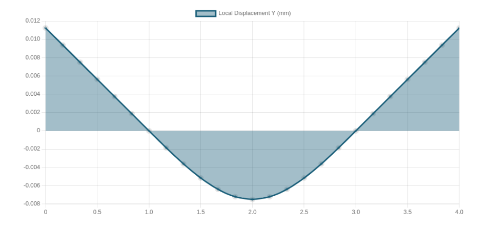
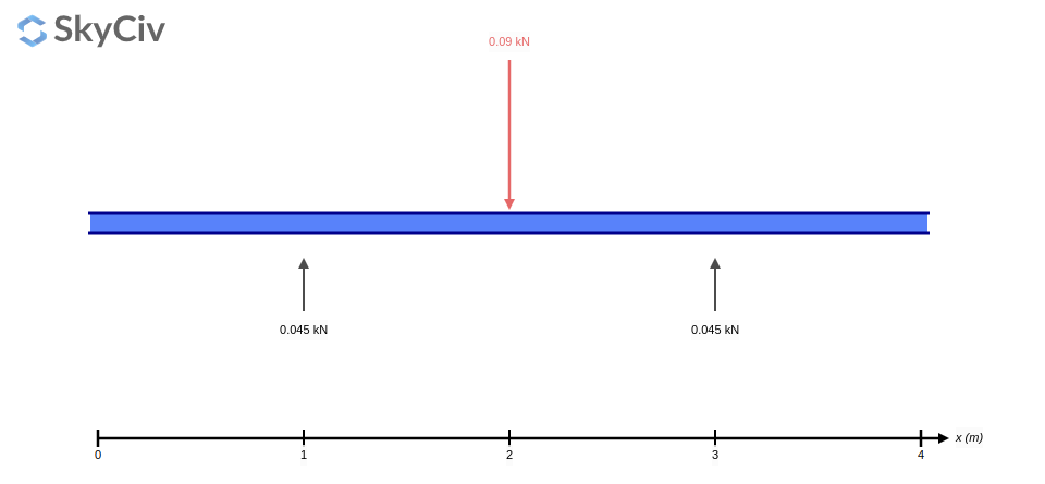
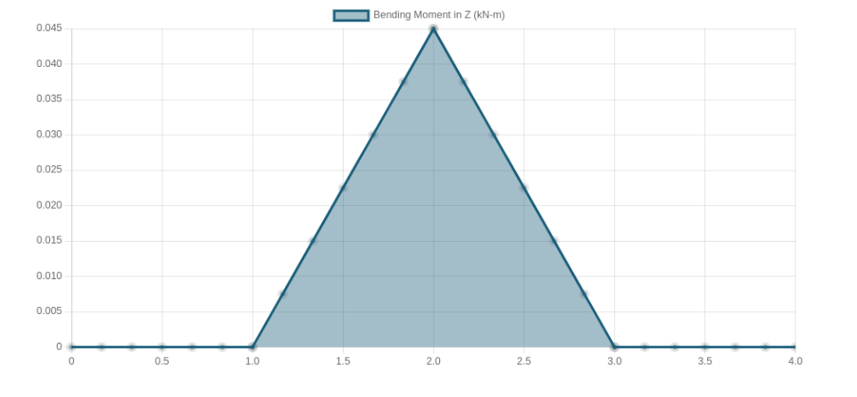
Actually, main focus has been on those traverse tubes connecting main tubes with gondola and so bearing the main load of a whole airship. I ran SkyCiv to demonstrate our situation (probably used this one before):

Reactions at Supports

Bending moment

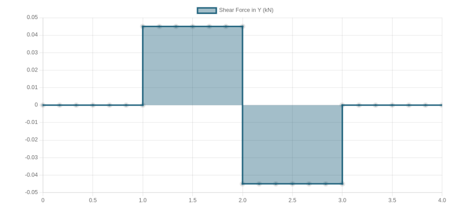
Shear Force Diagram

Deflection

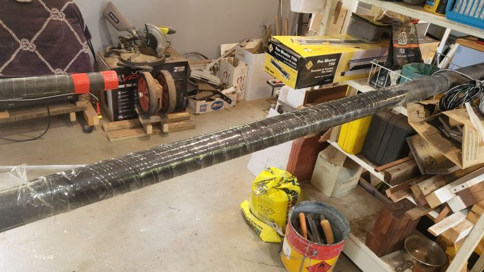
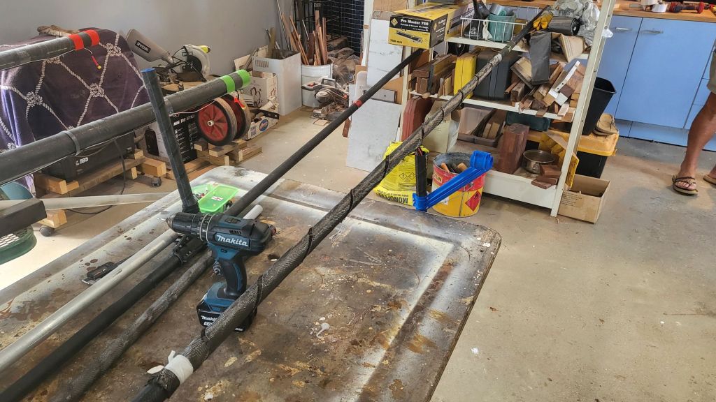
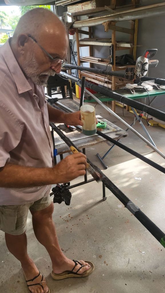
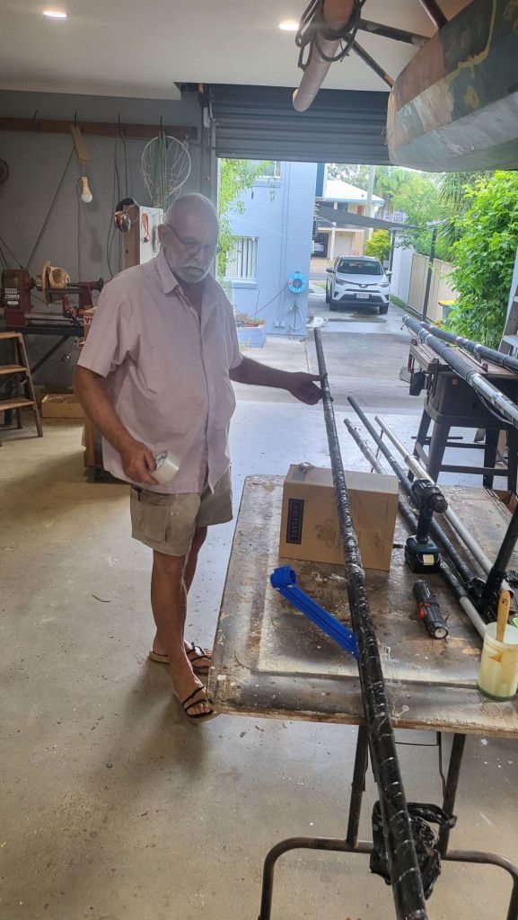
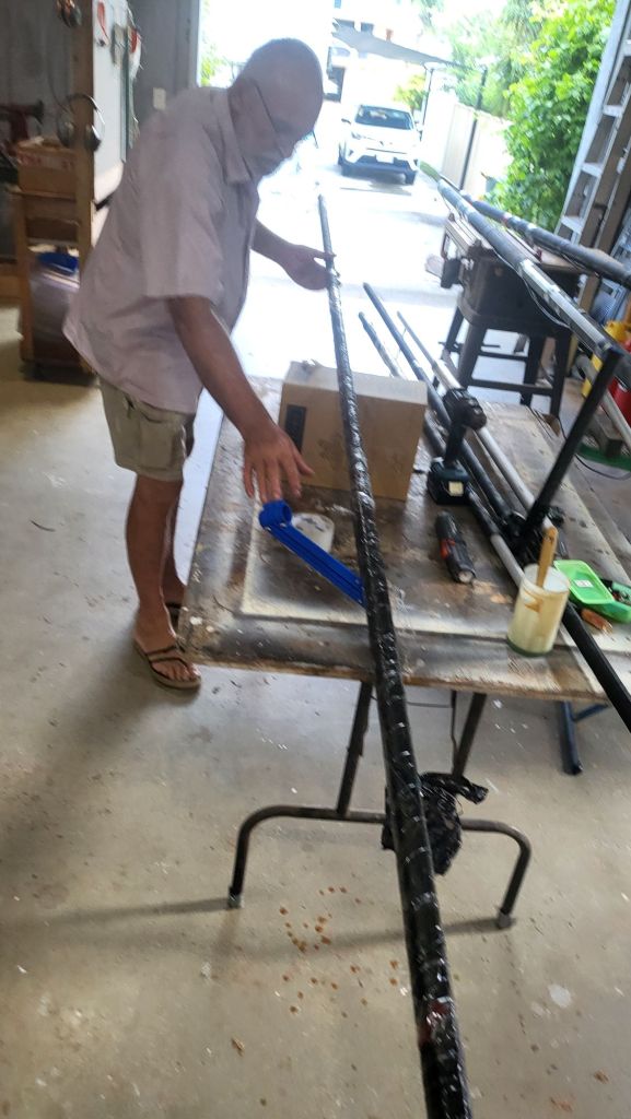
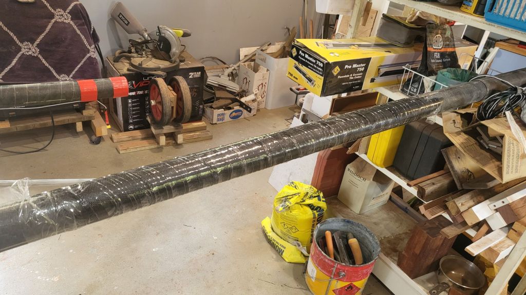
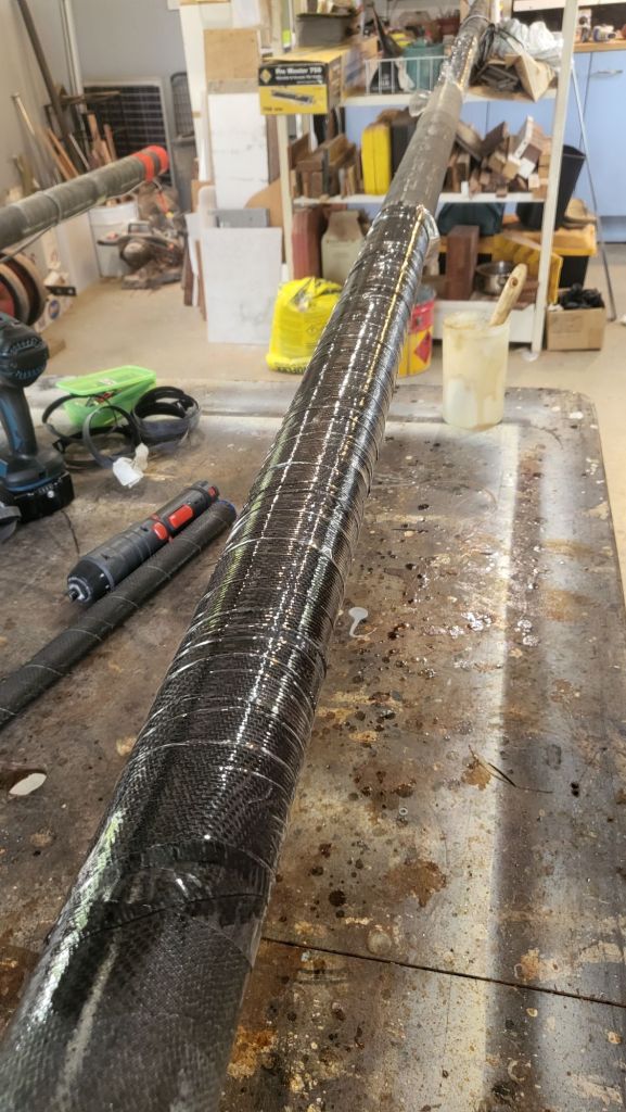
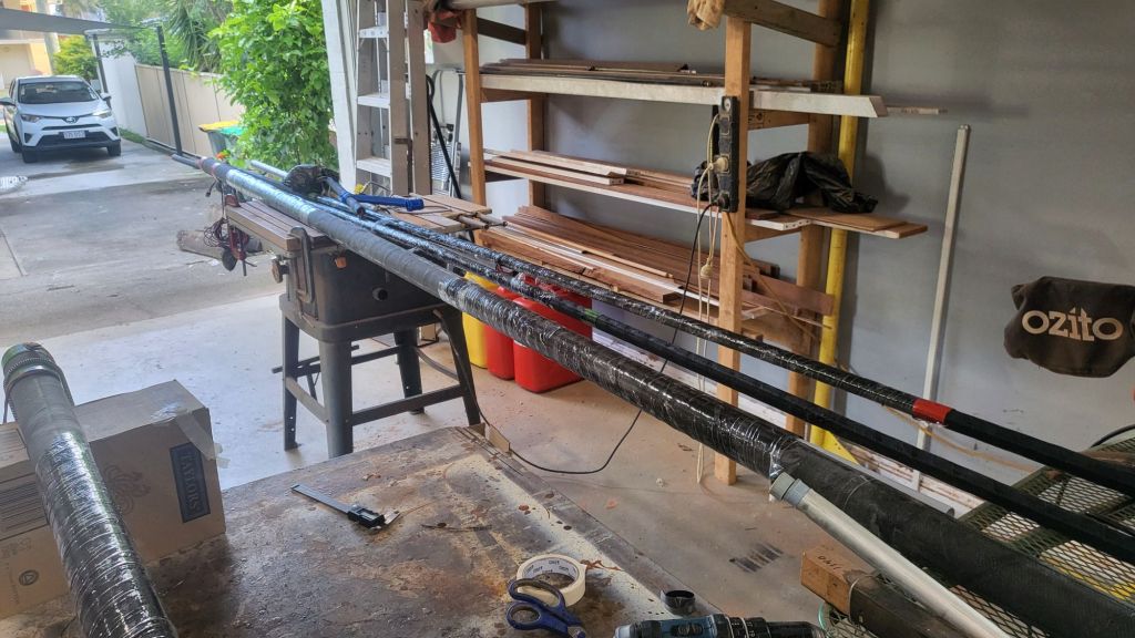
This is where Serge stepped up and over the past few weeks rethinking the reinforcement of our most critical CF tubes. Serge’s solution? Using leftover CF tape and polyester resin, he reinforced the high-stress zones. The result? A beautifully layered enhancement that practically doubled the strength of the traverse tubes. Enjoy watching Serge in action!

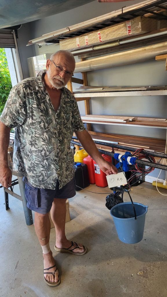
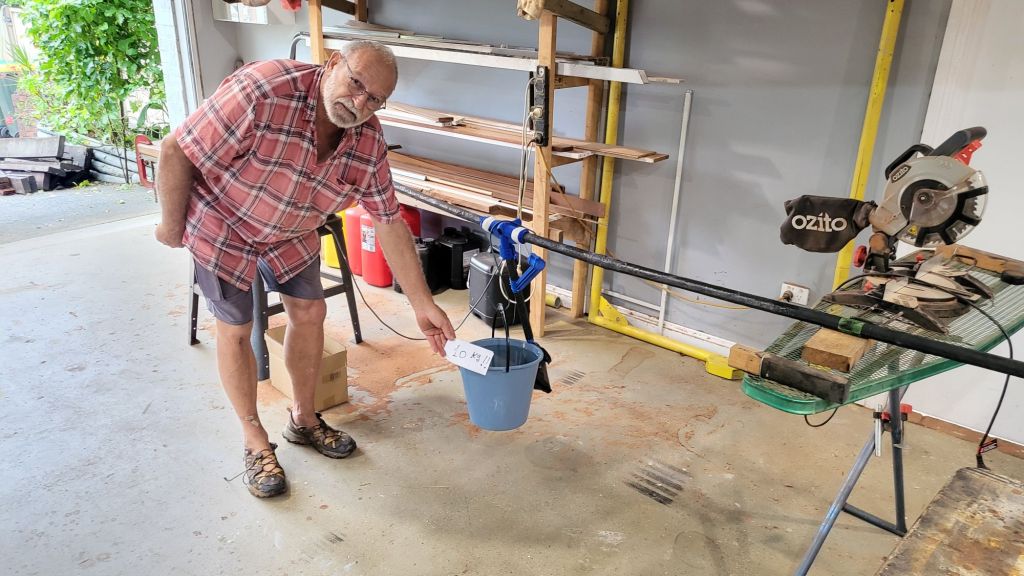
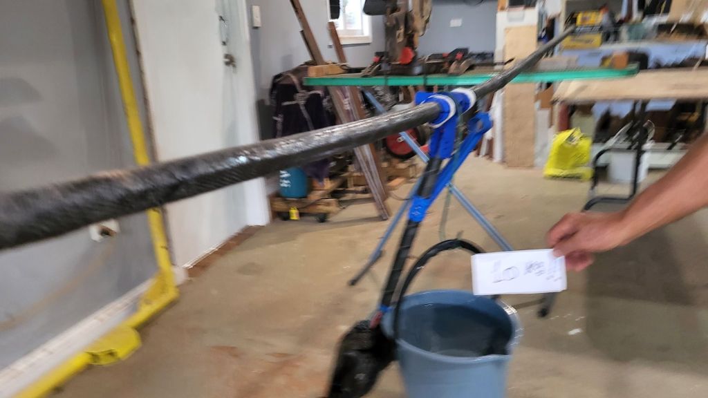
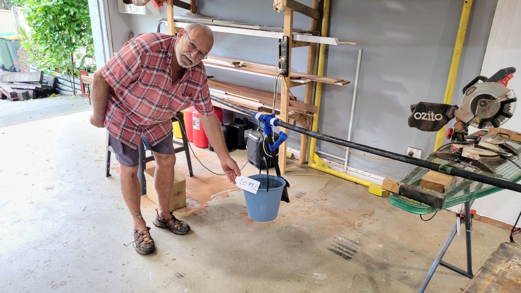
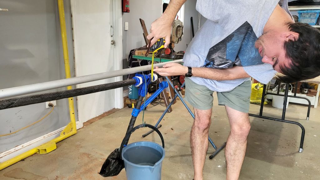
We weren’t going to stop just there. These reinforced tubes were put to the test—and passed with flying colours. They now comfortably support over 10kg of load, simulating real operational stress, including a suspended weight (like a 10kg water bucket) at the center span.

The tests didn’t just prove the design—they validated Serge’s craftsmanship and wisdom. It’s been an absolute privilege to learn from him and watch him bring decades of know-how into this project. Thank you Serge!