It has been a while, but we are moving ahead again.
For Phase II we need to develop two long carbon-fibre keel tubes: roughly 19 m long and 400 mm in diameter. They are meant to do much more than look tidy. They are the backbone of the airship: carrying the gondola and cross-beam loads, helping join the two hulls together, and eventually giving us a home for the keel-vectoring hardware.
That makes the tubes one of the big make-or-break pieces of the project. It is also a direct continuation of our Phase I tube adventures. Back then we learned how much work hides behind a nice-looking carbon tube: winding, heat, release, curing, a bit of stubbornness, and plenty of testing. Phase II is the same story – just with a rather more serious tube.
How light does it need to be?
The first planning placeholder was about 76 kg per keel, based on a 2 mm shell-equivalent wall. We would very much like to do better than that. Our current first-pass structural screen uses a 60 kg keel as a useful target, which corresponds to roughly a 1.58 mm uniform-wall equivalent before the real reinforcement zones, joins and fittings are designed.
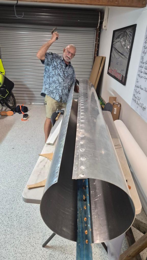
We have now gone back through the simplified lift and load picture rather than just waving our hands at a very long tube. In the 650 kg total-lift sensitivity case, after allowing for the envelope, a 60 kg keel, a 10 kg tip assembly and a 5 kg tail-vector assembly, the two main cross-beam stations per keel carry approximately:
61 kgat the front cross-beam;135 kgat the rear cross-beam.
The first global beam check is actually encouraging. It gives about 1.29 kN m of maximum bending moment at the rear cross-beam, an indicative 6.6 MPa outer-fibre bending stress and around 14 mm of relative deflection under the idealised static case. The important word there is first. It does not yet prove a flight-ready tube. The tricky work is still local reinforcement around the cross-beams, nacelles, joins and anything that wants to put a hole through our lovely tube. Gusts, thrust, handling and fatigue still need their own checks – but it is a much better place to start than a guess.
Back to the mould
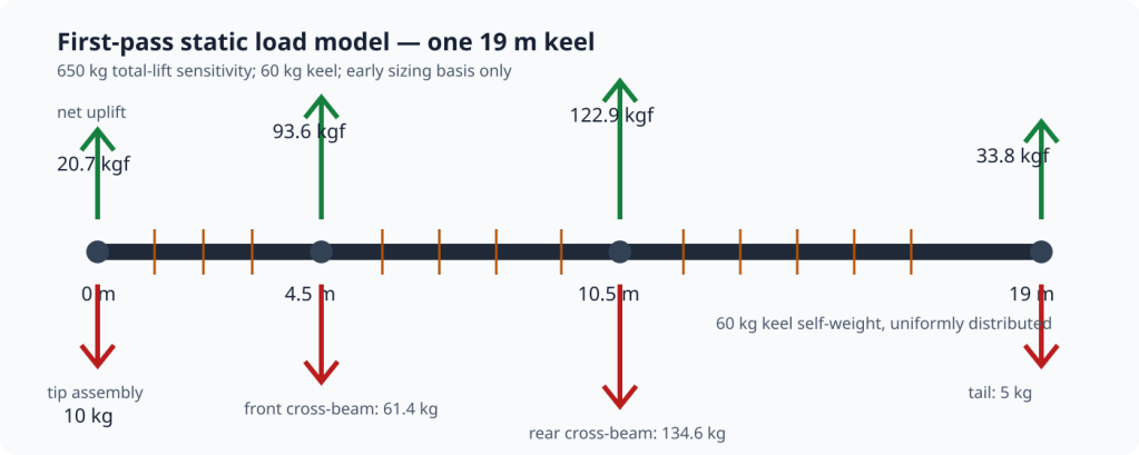
The manufacturing idea is familiar from Phase I. We will wrap carbon fibre around an aluminium mould, wet it with high-temperature epoxy, bring the cure zone up to roughly 100 C, and then let the part cure before cooling the mould back down. The mould is protected with Kapton tape and high-temperature release wax; the hope is that, after cooling, the finished tube lets go cleanly enough to slide the tooling along and continue the process towards a continuous keel.
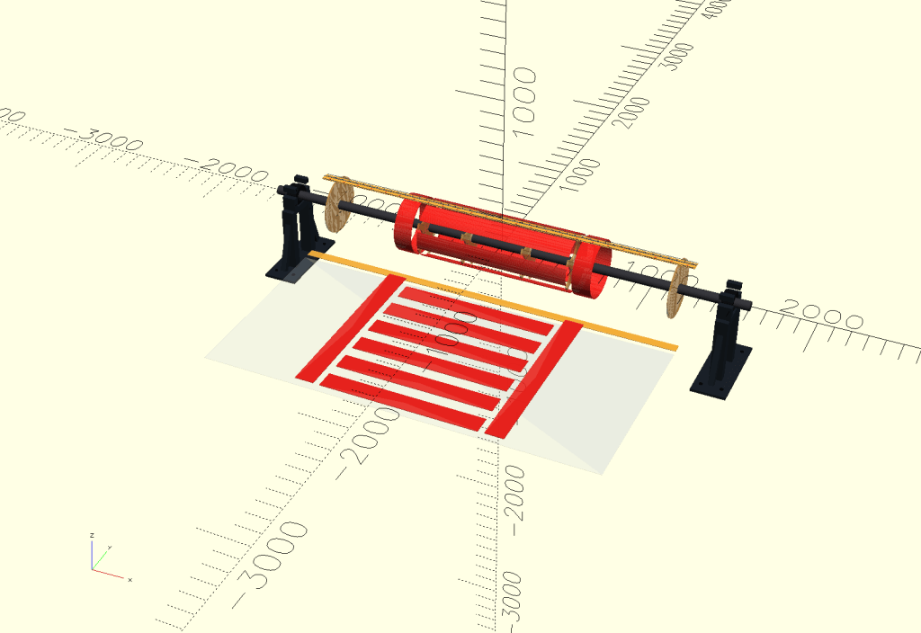
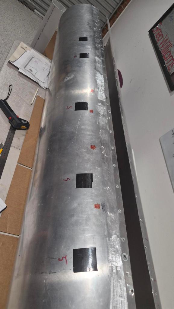
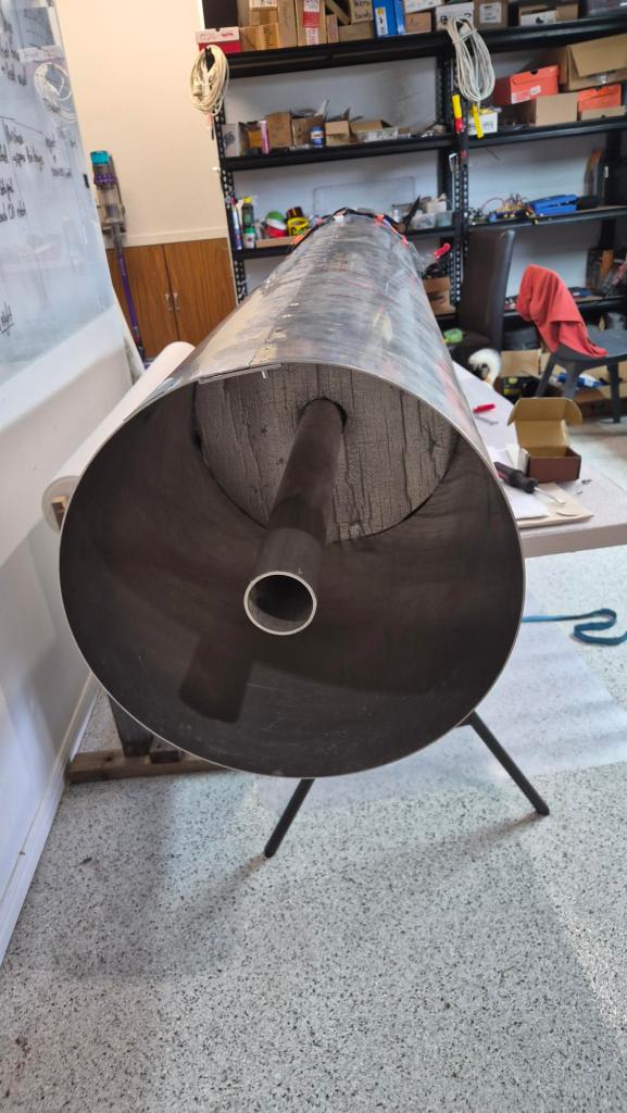
That is the theory. The workshop version is a 2.5 m long aluminium mould section made from a rolled 2500 x 1200 x 3 mm sheet. Its resulting outside diameter is about 382 mm, close enough to the planned 400 mm keel to make it a useful and honest process test.
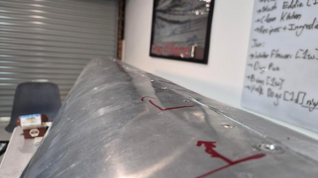
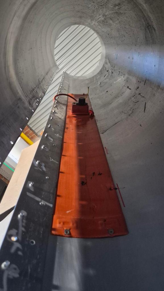
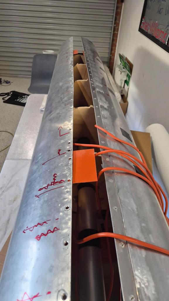
Rather than welding the rolled sheet permanently shut, we made it serviceable. An internal 60 mm aluminium seam strap is spot-welded along one side, then secured with nutserts and countersunk fasteners on the other. That means we can open the mould to get at heaters, wiring and partitions instead of turning a small mistake into a large aluminium paperweight.
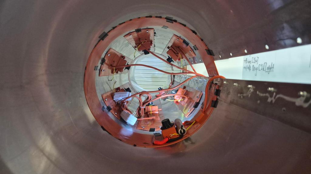
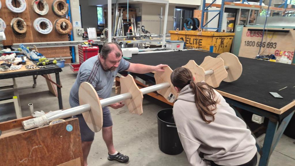
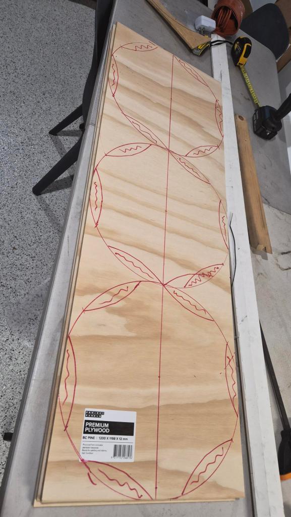
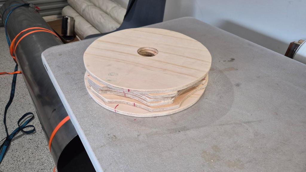
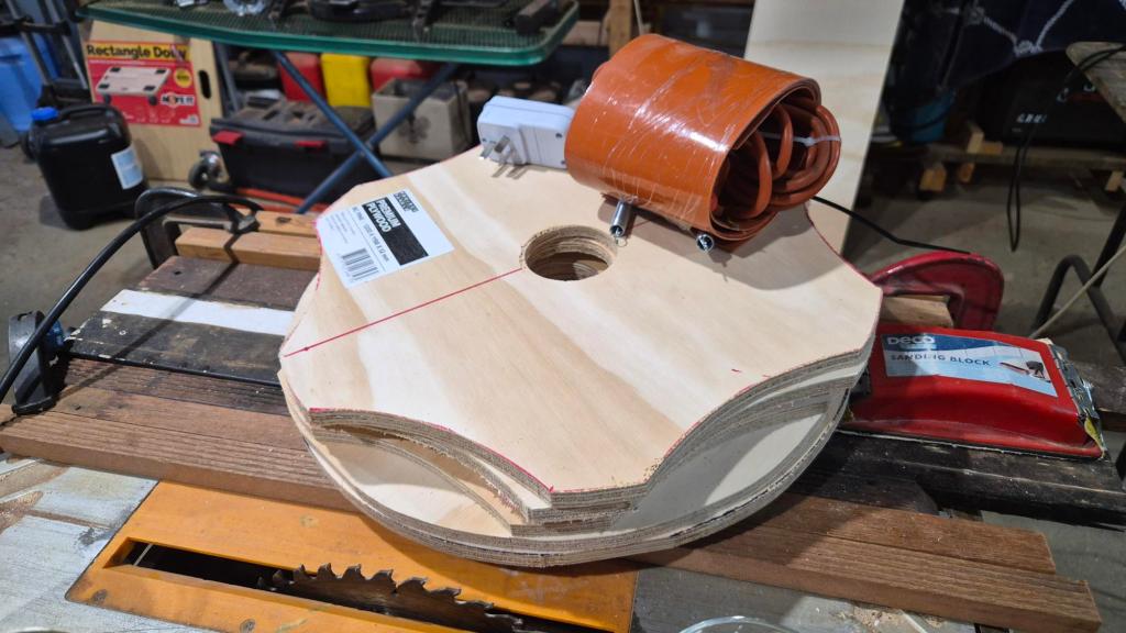
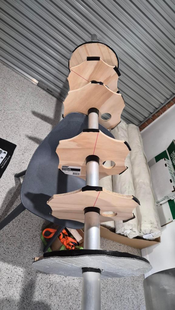
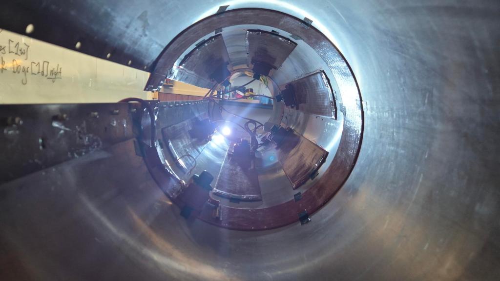
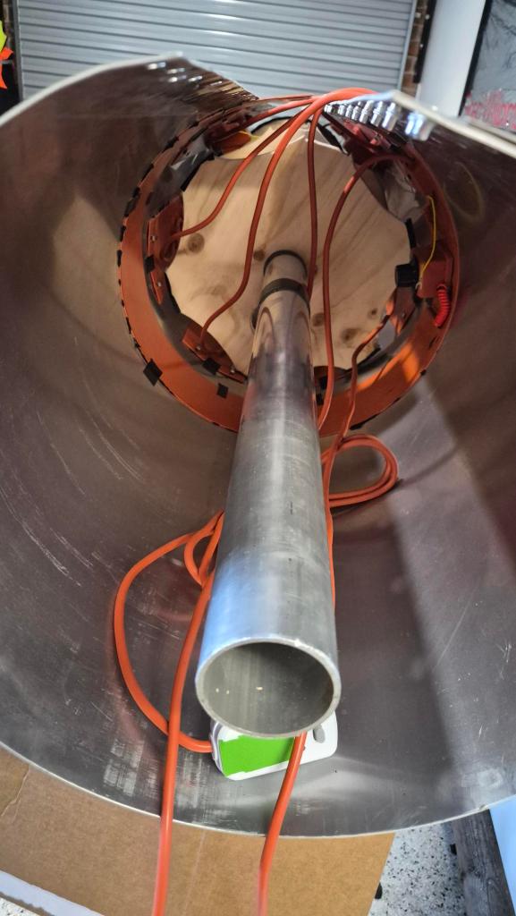
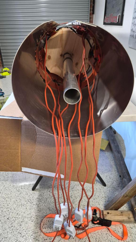
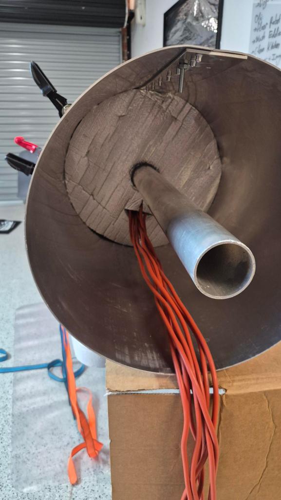
Inside are six plywood partitions, a central 60 mm axle and the beginnings of a spinning/winding jig. It is all there to keep the mould round, support it while we work, and leave us room to improve the process as we learn.
Making it hot
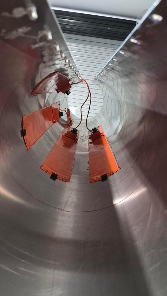
The cure is a big part of the experiment, so the mould is being fitted with flexible heater belts inside the aluminium shell. The plan is six axial belts (120 x 1000 mm, 300 W each), plus two belts around the circumference near the ends of the working zone (about 400 W each). At full power that is a potential 2.6 kW, so this is definitely not a casual plug-it-into-any-old 10 A workshop socket job.
One heater has already survived its first small test: after a 24 h adhesive cure, it stayed attached through an 80 C, one-hour heat run. Next we will fit the rest, check clearance around the partitions, and map the real temperature across the mould. The thermometer on a heater is not the same thing as knowing what the aluminium (and later the resin) are actually doing.
The people and the name
We started with the rolled aluminium sheet. Vilem helped weld the seam strap and fit the nutserts; Serge helped with the partitions; Kristian took on the less glamorous but very necessary clearing and sanding work. Once it was all coming together, it looked rather spectacular in the workshop.
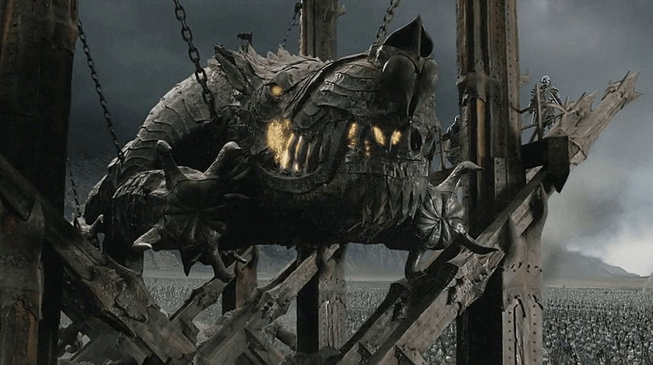
Serge also suggested that the mould needed a name. That felt correct. We have called it Grond – a nod to Tolkien’s famously formidable battering ram. Hopefully ours will be slightly friendlier to operate, and much less interested in knocking down city gates.
What happens next
First we finish the heater installation, prove that the mould warms evenly and sort out the practical winding support. Then come carbon layup trials, measured mass per metre, and reinforcement experiments around the real load stations.
The end goal is still a continuous 19 m keel tube, but we are deliberately getting there one workshop-sized lesson at a time. That is how the Phase I tube work got us this far, and it is how Grond will earn its name.
Gallery


One thought on “Grond: an update on our Phase II keel-tube development”