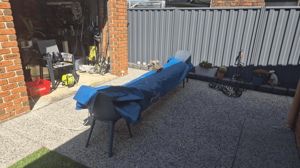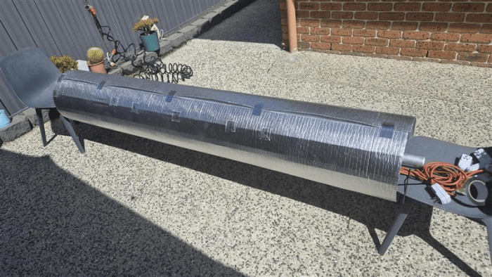
As a follow-up to our original Grond post, there have been some cool new developments. This update has two parts. First, we finally plugged the whole thing in and tested it. Second, after chatting with Serge, we started thinking about how to make Grond spin.
Target: 25°C to 100°C, then hold for 10 hours
As per our plan, the high-temperature epoxy process needs a long cure around 100–110°C, while Grond’s immediate target is to get from an ambient temperature of about 25°C to at least 100°C, then hold that temperature evenly for 10 hours.
There were so many things that could go wrong. The heating belts might not work, might not heat enough, or might not stay attached to the aluminium. The insulation might be inadequate. The power requirements and protection also needed attention. And, of course, the most important requirement was simply not setting anything on fire!
We had already tested a single belt, which got its local part of the mould to about 80°C and remained attached. That was useful, but clearly not the same as testing all the belts together with the mould insulated.
So to recap things a little – the complete installation has six 300 W axial belts and two approximately 400 W belts near the ends: 2.6 kW in total, assumption is that that should work out to about 10.8 A at 240 V, or 11.3 A at 230 V.
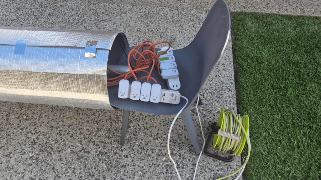
The belts were attached with SikaSeal Appliance Silicone Sealant. Sika lists it for aluminium and gives the cured sealant a temperature range of -50°C to 250°C. That is encouraging, although the real test for us is whether our particular bond survives repeated heat cycles on Grond.
The first complete heat test
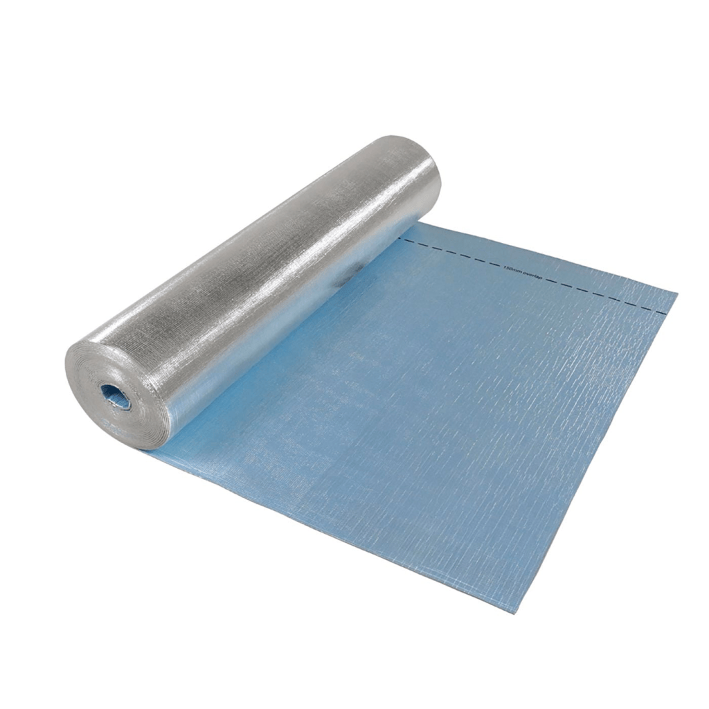
Grond got completely wrapped in one layer of Ametalin ThermalLiner HandyPack + six inspection openings and one reference opening were cut through to the tube, so we could follow the heating curve underneath the insulation. Small, consistent tape patches were stuck directly to the aluminium at the measuring points because an infrared thermometer does not read shiny aluminium reliably.
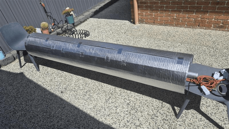
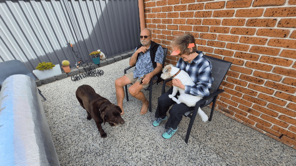
I then asked Serge and Robin to help with the test. We plugged in all the heating belts and measured every checkpoint at ten-minute intervals for 40 minutes. We also recorded the power being consumed at each reading.
The temperatures came together nicely at around 90°C across the working surface. That gave us confidence that the aluminium’s thermal conductivity is doing its job and spreading the belt heat around the mould.
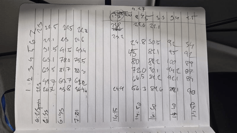
| Time | #1 +20 cm right | #2 middle | #3 -40 cm left | #4 -60 cm left | #5 -80 cm left | #6 edge (-125 cm) | #7 ambient | Power (kW) |
|---|---|---|---|---|---|---|---|---|
| 14:15 | 24.4 °C | 24.4 °C | 24.4 °C | 24.4 °C | 23.2 °C | 22.8 °C | 22.8 °C | 0 |
| 14:20 | 56.3 °C | 66.5 °C | 72.0 °C | 80.0 °C | 45.0 °C | 24.8 °C | 22.6 °C | 2.57 |
| 14:30 | 89.6 °C | 82.2 °C | 90.1 °C | 88.2 °C | 83.1 °C | 30.5 °C | 22.1 °C | 3.1 |
| 14:40 | 89.1 °C | 92.1 °C | 94.2 °C | 100.0 °C | 95.0 °C | 32.0 °C | — | 1.6 |
| 14:50 | 90.0 °C | 84.0 °C | 87.0 °C | 89.0 °C | 92.0 °C | 34.0 °C | — | 0.8 |
Temperatures were recorded using an IR thermometer and should be treated as indicative. Surface emissivity, viewing angle, and measurement position have clearly introduced error so the readings are most useful for showing the overall heating distribution and the sharp temperature fall-off beyond the belt ends.
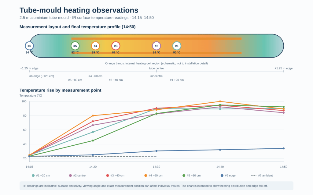
Strictly speaking, 40 minutes is not enough to claim a fully stabilised temperature, and it certainly is not yet our ten-hour cure test. Still, getting the whole working area close to 90°C was a very encouraging first result.
A little bit of heat-loss physics
Ninety degrees is at the lower edge of what we need, so the obvious question was: where is the remaining heat going?
The insulated working area, including the two circular ends, is roughly 1.75–2.05 m² depending on exactly where we draw the boundary. Ametalin gives one ThermalLiner layer a material thermal resistance of R0.11 m²·K/W.
Using the simple calculation:
heat loss = area × temperature difference / R-value
one ideal layer would lose roughly:
- 1.0–1.2 kW at 90°C in a 25°C workshop; and
- 1.2–1.4 kW at 100°C.
If three layers behaved perfectly and their R-values simply added together, that covered-surface loss would fall to approximately:
- 0.34–0.40 kW at 90°C; and
- 0.40–0.47 kW at 100°C.
The next easy trick up our sleeves is still to improve the side and end coverage and test a three-layer arrangement, preferably with controlled air gaps.
Post-test inspection
After everything cooled down, an endoscope inspection confirmed that all the belts were still in place and were not visibly peeling away from the aluminium. So far, the appliance silicone appears to be doing its job.
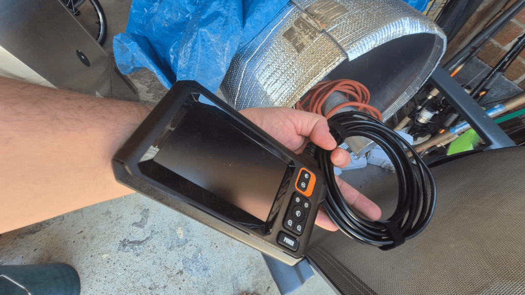
There was also a quite distinct smell at the beginning of the test, but it faded after a while. There is an idea that for the next run we should also introduce contact temperature probes under the insulation & withing the Grond itself. That will give us continuous readings at the centre, ends, seam and current coolest point instead of relying only on spot measurements with the infrared thermometer.
Make it spin
While chatting with Serge about what comes next, he made the point that Grond really needs assisted rotation from the beginning. Being able to rotate the mould around its longitudinal axis should make tape wrapping, consolidation, inspection and manufacturing in general much easier.
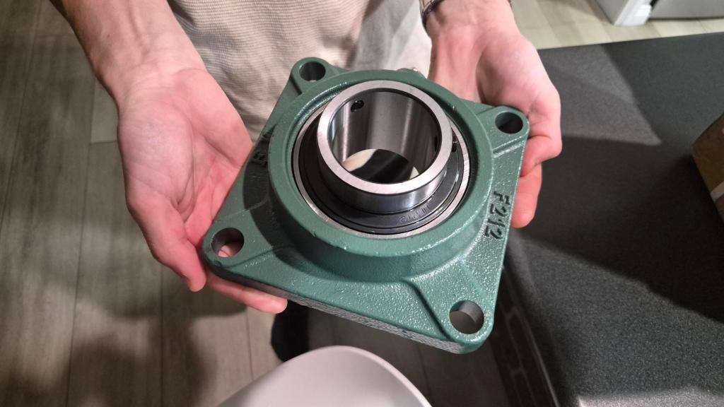
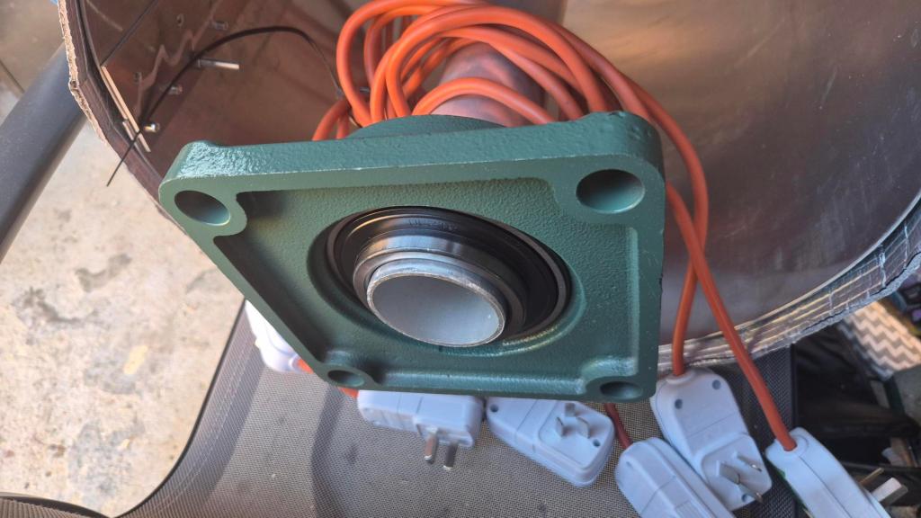
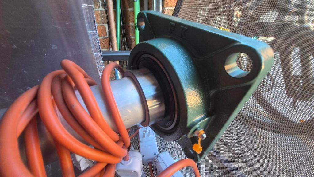
The obvious concept is a 60 mm inner axle supported at both ends by bearings. After some Googling, I found a UCF212 60 mm-bore, four-bolt square-flange housed bearing and ordered one straight away.
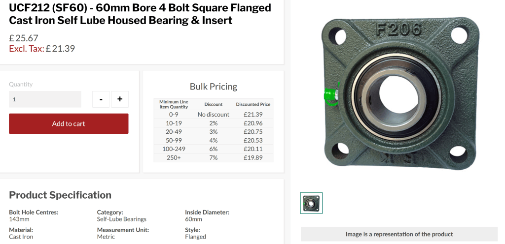
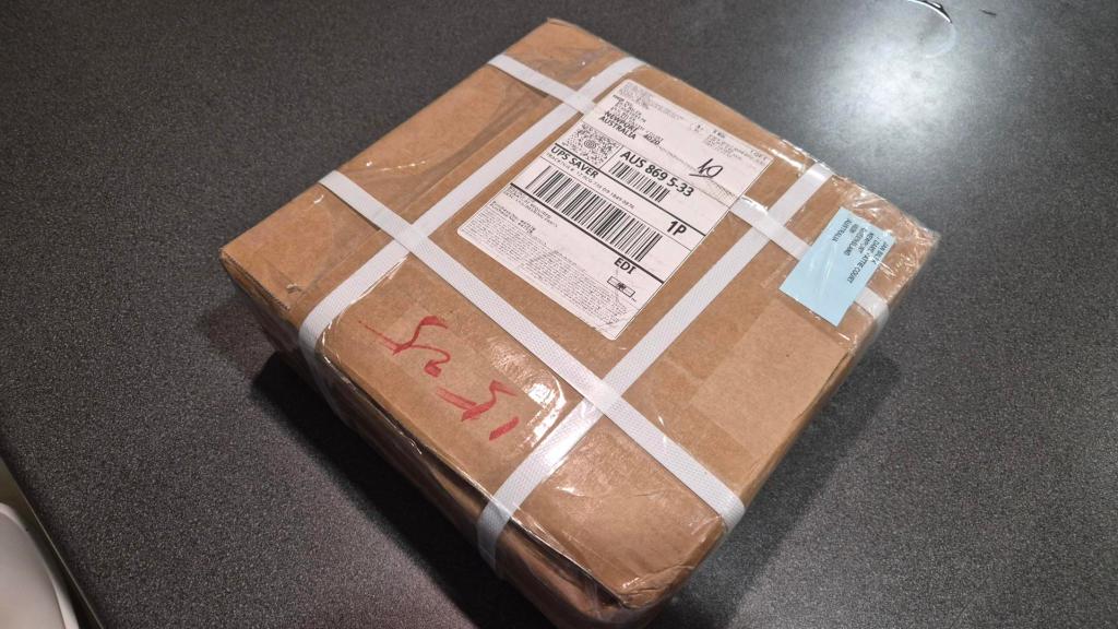
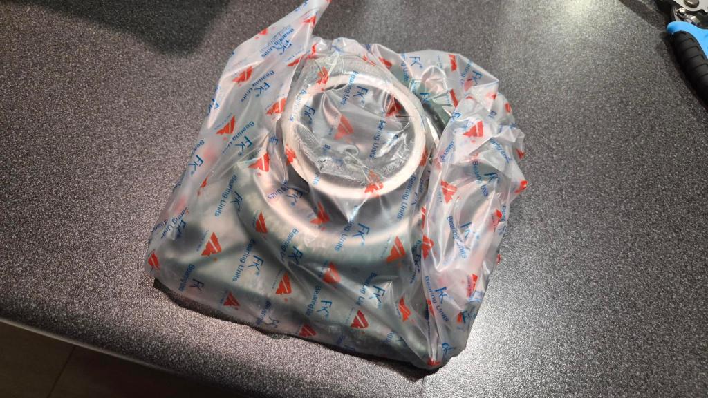
It arrived shortly afterwards and made an instant impression as a solid piece of machine tooling. The cast-iron unit is 175 mm square, with 143 mm bolt-hole centres and 19 mm mounting holes for M16 bolts. Naturally, I took some pictures to document it.
Buying a bearing is, of course, much easier than building the whole rotation system. So our next step is to design and test the complete jig.